Table of Contents for
X86 Assembly Language and C Fundamentals
 X86 Assembly Language and C Fundamentals
Published by
CRC Press, 2015
X86 Assembly Language and C Fundamentals
Published by
CRC Press, 2015
- X86 Assembly Language and C Fundamentals
- Preliminaries
- By the same Author
- X86 Assembly Language and C Fundamentals
- X86 Assembly Language and C Fundamentals
- Preface
- Chapter 1 Number Systems and Number Representations
- Chapter 2 X86 Processor Architecture
- Chapter 3 Addressing Modes
- Chapter 4 C Programming Fundamentals
- Chapter 5 Data Transfer Instructions
- Chapter 6 Branching and Looping Instructions
- Chapter 7 Stack Operations
- Chapter 8 Logical, Bit, Shift, and Rotate Instructions
- Chapter 9 Fixed-Point Arithmetic Instructions
- Chapter 10 Binary-Coded Decimal Arithmetic Instructions
- Chapter 11 Floating-Point Arithmetic Instructions
- Chapter 12 Procedures
- Chapter 13 String Instructions
- Chapter 14 Arrays
- Chapter 15 Macros
- Chapter 16 Interrupts and Input/Output Operations
- Chapter 17 Additional Programming Examples
- Appendix A ASCII Character Codes
- Appendix B Answers to Select Problems
Chapter 12
Procedures
A procedure is a set of instructions that perform a specific task. They are invoked from another procedure — the calling procedure (or program) — and provide results to the calling program at the end of execution. Procedures (also called subroutines) are utilized primarily for routines that are called frequently by other procedures. The procedure routine is written only once, but used repeatedly; thereby, saving storage space. Procedures permit a program to be coded in modules; thus, making the program easier to code and test.
A program can contain many procedures. Each procedure is delimited by the PROC and ENDP directives and contains identical names for each directive, as shown below. Each procedure must have a unique name.
Calc PROC NEAR/FAR
.
.
.
Calc ENDP
Comments are normally placed at the beginning of a procedure to indicate the purpose of the procedure. A procedure is invoked from a program by means of the CALL instruction, which can occur anywhere in the calling program, and terminated by the RET instruction, which returns control to the calling program. Control is returned to the instruction that immediately follows the CALL instruction in the invoking program. A calling procedure can pass parameters or the addresses of the parameters on the stack to be used by the invoked procedure or pass parameters by placing them in general-purpose registers that can be accessed by the invoked procedure.
12.1 Call a Procedure
The CALL instruction is used to call a procedure, either in the current code segment (near call — also referred to as an intrasegment call) or in a different code segment (far call — also referred to as an intersegment call). The syntax for a CALL instruction is shown below.
CALL procedure name label
A near call pushes the value of the updated (E)IP register onto the stack; thus, it points to the instruction that immediately follows the CALL instruction — this instruction is executed upon returning from the called procedure to the calling program. Then a branch occurs to the destination (target) address. The destination address for a near call can be either an absolute offset or a relative offset.
An absolute offset points to an address that is an offset from the base of the current code segment. An absolute offset is obtained indirectly through a general-purpose register or from a memory location, as shown below using the EBX register for an indirect call. The contents of the EBX register contains an offset in memory.
CALL [EBX]
The absolute offset is stored in the (E)IP register; if the operand-size attribute is 16, then the high-order half of the EIP register is reset. A relative offset is a signed displacement that is added to the (E)IP register and is usually specified as a label that is encoded as an immediate value. The CS register is not changed for near calls, because the target address is in the current code segment.
Afar call pushes the CS register onto the stack and the updated value of the (E)IP register onto the stack. Then the far call loads the CS register with the segment selector of the invoked procedure and loads the offset of the invoked procedure into the (E)IP register. The target address for the called procedure is a far address obtained directly from a pointer in the instruction or indirectly through a memory location.
With the direct method, the target address of the invoked procedure — containing the segment and offset — is encoded in the instruction using either a 4-byte or a 6-byte immediate value. For a 4-byte immediate value, the low-order two bytes are loaded into the IP register and the high-order two bytes are loaded into the CS register. For a 6-byte immediate value, the low-order four bytes are loaded into the EIP register and the high-order two bytes are loaded into the CS register. A branch is then executed to the subroutine.
With the indirect method, the target address is located in memory and contains either a 4-byte or a 6-byte address. For a 4-byte value, the low-order two bytes are loaded into the IP register and the high-order two bytes are loaded into the CS register. For a 6-byte value, the low-order four bytes are loaded into the EIP register and the high-order two bytes are loaded into the CS register. A branch is then executed to the subroutine.
12.2 Return from a Procedure
The RET instruction transfers control from an invoked procedure to the instruction immediately following the CALL instruction in the calling procedure. When executing an intrasegment near return, the processor pops the value at the stack top to the (E)IP register, adds an optional immediate value to the stack pointer, then continues execution of the invoking procedure.
When executing an intersegment far return, the processor pops the value at the stack top to the (E)IP register, then pops the value at the new stack top to the CS register and adds an optional immediate value to the stack pointer, then continues execution of the invoking procedure. The immediate optional value is used to remove parameters from the stack that were placed on the stack by the invoking procedure. The syntax for a RET instruction is shown below.
RET optional immediate value
12.3 Passing Parameters to a Procedure
Parameters (arguments) can be passed to a subroutine (procedure) by means of the stack, general-purpose registers, or by placing the addresses of the parameters in general-purpose registers. Since the contents of the GPRs are not saved prior to executing a CALL instruction, all six GPRs — EAX, EBX, ECX, EDX, ESI, and EDI — can be used to pass parameters to the invoked procedure. Registers ESP and EBP, however, cannot be used to pass parameters. The calling program can save the GPRs on the stack, in memory, or in a data segment before calling the procedure.
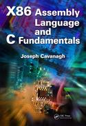
Passing parameters using the stack The code segment in Figure 12.1 illustrates using the stack to pass parameters to the called procedure. The calling program passes the augend and addend to a procedure by pushing them onto the stack. The invoked procedure then performs the addition operation and returns the sum to the calling program in the EAX register.
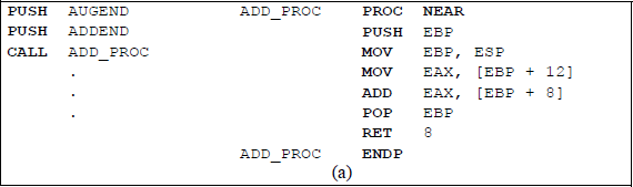
Program segment to illustrate passing parameters to an invoked procedure using the stack; the procedure adds two operands and returns the sum: (a) the program segment and (b) the stack.
The calling program pushes the augend and the addend onto the stack, then calls the ADD_PROC procedure. The procedure is a near procedure; therefore, only the EIP register is placed on the stack. The invoked procedure pushes the EBP register onto the stack — the EBP register will be used to access the augend and the addend. Then the value of the ESP register — which points to the location of EBP on the stack — is moved to EBP. The EBP register can now be used to access data on the stack.
The augend is then moved to register EAX by the instruction shown below. The augend is located 12 bytes above the address of EBP (ESP); therefore, a value of 12 is added to the contents of the EBP register.
MOV EAX, [EBP + 12]
An ADD instruction then adds the contents of register EAX (augend) to the contents of the stack at location EBP + 8 (addend) and places the sum in register EAX. Then the initial contents of register EBP are popped off the stack and stored in EBP. A near return instruction is then executed, which pops EIP off the stack; register ESP now points to the addend. In order to restore the contents of the ESP register to its initial value, an immediate value of eight is added to the ESP register upon returning to the calling procedure. The invoked procedure is delimited by the PROC and ENDP directives, both of which contain the name of the invoked procedure.
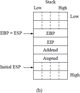
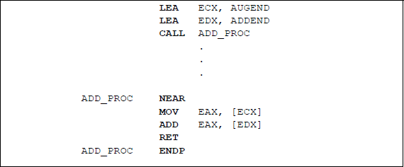
Passing parameters using general-purpose registers All six general-purpose registers — EAX, EBX, ECX, EDX, ESI, and EDI — can be used to transfer parameters to an invoked procedure. The operands are moved to the applicable registers prior to calling the procedure; the procedure can then access the registers directly to perform the specified operation. Since the stack is not used to store the operands before calling the procedure, there is no immediate value added to a near return. Figure 12.2 shows a program segment to add two operands using a near procedure. Although this program segment is relatively simple, it illustrates how general-purpose registers can be used to pass parameters to an invoked procedure.
A near procedure to add two operands by passing the operands to the procedure using general-purpose registers.
Passing parameters by indirect addressing In this method, the effective addresses of the parameters are loaded into general-purpose registers prior to calling the procedure. The procedure then uses the indirect addressing mode to access the parameters. Figure 12.3 uses this technique to add two operands.
A near procedure to add two operands by passing the addresses of the operands to the procedure using general-purpose registers.
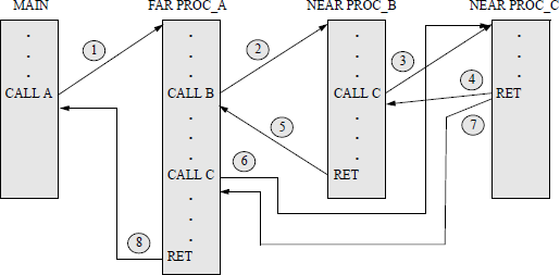
Example 12.1 This example provides a sequence of calls and returns to and from near and far procedures. There will be a total of four calls and four returns, as shown below. There is a main program, a far procedure called PROC_A, a near procedure called PROC_B, and a near procedure called PROC_C.
The first operation is a call from the main program to far PROC_A.
The second operation is a call from PROC_A to near PROC_B.
The third operation is a call from PROC_B to near PROC_C.
The fourth operation is a return from PROC_C to PROC_B.
The fifth operation is a return from PROC_B to PROC_A.
The sixth operation is a call from PROC_A to near PROC_C.
The seventh operation is a return from PROC_C to PROC_A.
The eighth operation is a return from PROC_A to the main program.
The above eight sequence of operations is shown pictorially in Figure 12.4.
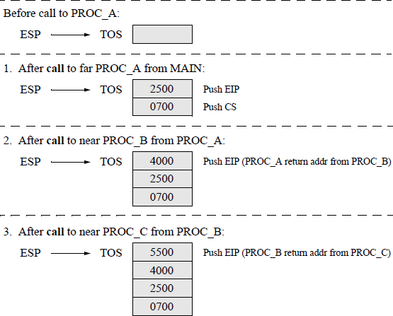
The eight sequences for the various operations together with applicable addresses for the CS register and the EIP register are shown below. Figure 12.5 shows the sequence of operations and the contents of the stack for each operation.
MAIN program calls far procedure PROC_A.
MAIN program return address from PROC_A call: CS = 0700, EIP = 2500.
PROC_A calls near PROC_B.
PROC_A return address from PROC_B call: EIP = 4000.
PROC_B calls near PROC_C.
PROC_B return address from PROC_C call: EIP = 5500.
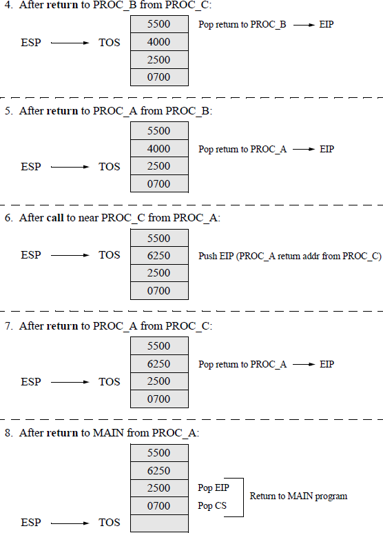
Return to PROC_B.
Return to PROC_A.
PROC_A calls near PROC_C.
PROC_A return address from PROC_C call: EIP = 6250.
Return to PROC_A.
Return to main program.
The parameter list is reproduced in Figure 12.6 for convenience. The name PARLST (parameter list) in the data segment of a program is the name of a one-dimensional array that is labelled as a byte array and accepts input data from the keyboard.

The first array element (MAXLEN) specifies the maximum number of characters that can be entered; the second array element (ACTLEN) indicates the actual number of characters that were entered from the keyboard; the third element of the array (OPFLD) contains the beginning of the operand field where the operands from the keyboard are stored — the last byte in the operand field is the Enter (carriage return) character (↵).
Figure 12.7 shows an assembly language program — not embedded in a C program — that illustrates the application of a procedure to add two single-digit numbers that are entered from the keyboard. The procedure utilizes the ASCII adjust for addition (AAA) instruction. The two numbers are prepared for the AAA instruction, then pushed onto the stack to be added by the CALC procedure.
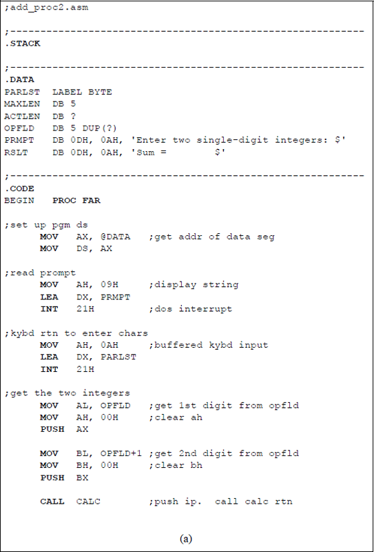
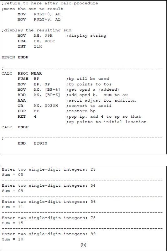
Program to illustrate the application of a procedure: (a) the program and (b) the outputs.
Recall that the AAA instruction adjusts the result of an addition operation of two ASCII operands. ASCII numerical digits have a high-order four bits of 3H when entered from the keyboard. The AAA instruction produces an unpacked BCD number which contains zeroes in the high-order four bits of the byte; the numerical value of the number is contained in the low-order four bits of the byte. General-purpose register AL is the implied source and destination for the AAA instruction.
The sum obtained from adding the two ASCII numbers may not be a valid BCD value. If the low-order four bits of the sum in register AL are greater than nine or if the AF flag is set, then six is added to AL and register AH is incremented by 1. The AAA instruction converts the sum in register AL into a valid BCD number and stores the result in bits 3 through 0 of register AL and resets bits 7 through 4 of register AL.
Shown below is an example in which the low-order four bits of the result are not a valid BCD number; that is, a digit (C) that is greater than nine. When used in a program, the AAA instruction is preceded by an ADD instruction or an ADC instruction.
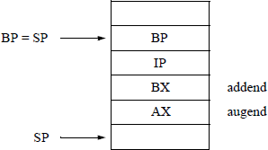
The register stack for the program of Figure 12.7 is shown in Figure 12.8. The calling program first pushes the operand in AX onto the stack and then pushes the operand in BX onto the stack. The CALL to the near CALC procedure pushes IP onto the stack. The procedure then pushes the base pointer, BP, onto the stack to be used as an offset in the stack segment. In order to accomplish this, BP is made equal to the stack pointer, SP, so that BP points to the top of stack.
12.4 Problems
12.1 Write an assembly language program — not embedded in a C program — that uses a procedure to multiply two single-digit operands. Enter several operands for the multiplicand and multiplier and display the products.
12.2 Write an assembly language program — not embedded in a C program — that uses a procedure to obtain the area of a triangle from two integers that are entered from the keyboard. Enter several sets of single-digit numbers for the base and height and display the areas.
12.3 Calculate the area of a triangle using an assembly language module embedded in a C program. Floating-point numbers for the base and height are entered from the keyboard. In this problem, a procedure is not necessary. Unlike Problem 12.2, odd-valued bases will not be truncated. Enter several floatingpoint numbers for the base and height and display the areas.
12.4 Write an assembly language program — not embedded in a C program — that uses a procedure to exclusive-OR six hexadecimal characters that are entered from the keyboard. The following characters are exclusive-ORed: the first and third; the second and fourth; the third and fifth; and the fourth and sixth. The keyboard data can be any hexadecimal characters; for example, 2T/}b*.
12.5 Write an assembly language program — not embedded in a C program — that uses a procedure to convert an 8-bit binary code number to the corresponding Gray code number. The binary number is entered from the keyboard.