Table of Contents for
X86 Assembly Language and C Fundamentals
 X86 Assembly Language and C Fundamentals
Published by
CRC Press, 2015
X86 Assembly Language and C Fundamentals
Published by
CRC Press, 2015
- X86 Assembly Language and C Fundamentals
- Preliminaries
- By the same Author
- X86 Assembly Language and C Fundamentals
- X86 Assembly Language and C Fundamentals
- Preface
- Chapter 1 Number Systems and Number Representations
- Chapter 2 X86 Processor Architecture
- Chapter 3 Addressing Modes
- Chapter 4 C Programming Fundamentals
- Chapter 5 Data Transfer Instructions
- Chapter 6 Branching and Looping Instructions
- Chapter 7 Stack Operations
- Chapter 8 Logical, Bit, Shift, and Rotate Instructions
- Chapter 9 Fixed-Point Arithmetic Instructions
- Chapter 10 Binary-Coded Decimal Arithmetic Instructions
- Chapter 11 Floating-Point Arithmetic Instructions
- Chapter 12 Procedures
- Chapter 13 String Instructions
- Chapter 14 Arrays
- Chapter 15 Macros
- Chapter 16 Interrupts and Input/Output Operations
- Chapter 17 Additional Programming Examples
- Appendix A ASCII Character Codes
- Appendix B Answers to Select Problems
Chapter 8
Logical, Bit, Shift, and Rotate Instructions
The logical operations of AND, OR, exclusive-OR, NOT, and TEST are presented in this chapter; these instructions execute the Boolean equivalent of the corresponding operations in digital logic circuits. Also covered are the instructions that operate on single bits, such as bit test (BT), bit test and set (BTS), bit test and reset (BTR), bit test and complement (BTC), bit scan forward (BSF), and bit scan reverse (BSR).
Shift instructions are also presented that perform logical or arithmetic left or right shifts on bytes, words, or doublewords. The shift instructions are shift arithmetic left (SAL), shift logical left (SHL), shift arithmetic right (SAR), shift logical right (SHR), double precision shift left (SHLD), and double precision shift right (SHRD). The rotate instructions include rotate left (ROL), rotate right (ROR), rotate through carry left (RCL), and rotate through carry right (RCR). Also covered is the set byte on condition (SETcc) instruction.
8.1 Logical AND Instruction
The AND instruction performs the bitwise AND operation of two operands — the first operand (destination) and the second operand (source) and stores the result in the destination operand. The source operand can be located in a general-purpose register, in memory, or can be an immediate operand. The destination operand can be in a general-purpose register or a memory location; however, both operands cannot be in memory. The syntax for the logical AND instruction is shown below.
AND register/memory, register/memory/immediate
The truth table for the AND function is shown in Table 8.1 and corresponds to the Boolean product. The variables x1 , x2 , and z1 represent a bit in the destination operand, a bit in the source operand, and the resulting bit in the destination operand, respectively. The AND instruction can be used to mask off particular bits; that is, to reset certain bits, because any bit that is ANDed with a 0 bit results in a 0 bit. The affected flags are the parity flag (PF), the sign flag (SF), and the zero flag (ZF) — the overflow flag (OF) and the carry flag (CF) are set to 0. Examples of the AND function are shown in Table 8.2(a) and Table 8.2(b). Table 8.2(b) masks off the high-order four bits.
Examples of the AND Function for Eight Bits
AND |
||||||||||||||||
|---|---|---|---|---|---|---|---|---|---|---|---|---|---|---|---|---|
0 |
1 |
1 |
0 |
1 |
1 |
0 |
1 |
1 |
1 |
1 |
1 |
1 |
1 |
1 |
1 |
|
0 |
0 |
1 |
1 |
1 |
1 |
1 |
0 |
0 |
0 |
0 |
0 |
1 |
0 |
1 |
0 |
|
0 |
0 |
1 |
0 |
1 |
1 |
0 |
0 |
0 |
0 |
0 |
0 |
1 |
0 |
1 |
0 |
|
(a) |
(b) |
|||||||||||||||
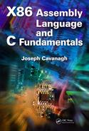
Figure 8.1 shows an assembly language module embedded in a C program that illustrates using the AND function to mask off certain bits in a hexadecimal number that is entered from the keyboard. The number is moved to the EAX register, then the AND instruction resets the high-order 28 bits; that is, bits 31 through 4 by the instruction shown below.
AND EAX, 0000000FH
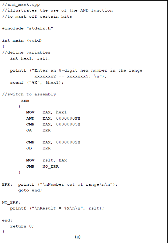
Program to illustrate using the AND instruction to mask off certain bits: (a) the program and (b) the outputs.
The program checks to determine if the modified number is in the range 00000002H through 00000005H. If the number is within the range, then the number is displayed. If the number is not in the specified range, then an error message is displayed.
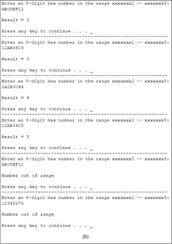
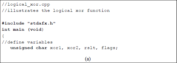
Figure 8.2 contains an assembly language module embedded in a C program that illustrates the logical AND function of two operands. The program displays the result of the AND operation together with the resulting flags. The unsigned type modifier is applied to the char data type. An unsigned character has a range from 0 to 255; a signed character, char, has a range from –128 to +127.
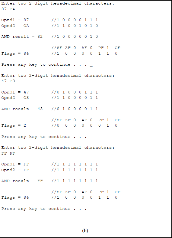
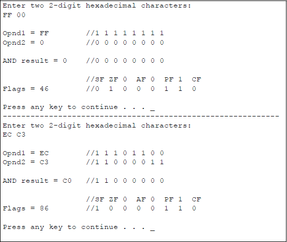
Program to illustrate the logical AND operation and resulting flags: (a) the program and (b) the outputs.
The two operands, opnd1 and opnd2, are moved to registers AL and BL, respectively, prior to the AND operation. The load AH from flags (LAHF) instruction stores the low-order byte (shown below) of the EFLAGS register in the AH register. Bit positions 1, 3, and 5 are reserved. The flags and result are then moved to the flags variable and the rslt variable to be displayed.
7 |
6 |
5 |
4 |
3 |
2 |
1 |
0 |
|---|---|---|---|---|---|---|---|
SF |
ZF |
0 |
AF |
0 |
PF |
1 |
CF |
8.2 Logical Inclusive-OR Instruction
The OR instruction performs the bitwise OR operation of two operands — the first operand (destination) and the second operand (source) and stores the result in the destination operand. The source operand can be located in a general-purpose register, in memory, or can be an immediate operand. The destination operand can be in a general-purpose register or a memory location; however, both operands cannot be in memory. The syntax for the logical OR instruction is shown below.
OR register/memory, register/memory/immediate
The truth table for the OR function is shown in Table 8.3 and corresponds to the Boolean sum. The variables x1 , x2 , and z1 represent a bit in the destination operand, a bit in the source operand, and the resulting bit in the destination operand, respectively. The OR instruction can be used to set particular bits; that is, to set certain bits to a value of 1, because any bit that is ORed with a 1 bit results in a 1 bit. The affected flags are the parity flag (PF), the sign flag (SF), and the zero flag (ZF) — the overflow flag (OF) and the carry flag (CF) are set to 0. Examples of the OR function are shown in Table 8.4(a) and Table 8.4(b). Table 8.4(b) sets all the bits to a value of 1 regardless of their original value.
Examples of the OR Function for Eight Bits
OR |
||||||||||||||||
|---|---|---|---|---|---|---|---|---|---|---|---|---|---|---|---|---|
0 |
1 |
1 |
0 |
0 |
1 |
0 |
1 |
0 |
0 |
1 |
1 |
0 |
0 |
1 |
0 |
|
0 |
0 |
1 |
0 |
1 |
0 |
0 |
1 |
1 |
1 |
1 |
1 |
1 |
1 |
1 |
1 |
|
0 |
1 |
1 |
0 |
1 |
1 |
0 |
1 |
1 |
1 |
1 |
1 |
1 |
1 |
1 |
1 |
|
(a) |
(b) |
|||||||||||||||
Figure 8.3 contains an assembly language module embedded in a C program that illustrates the logical OR function of two operands. The program displays the result of the OR operation together with the resulting flags.
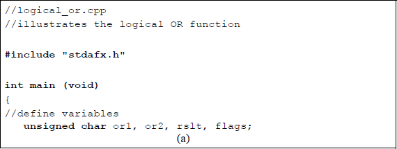
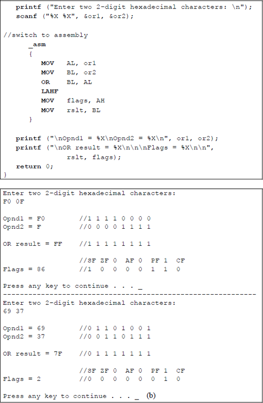
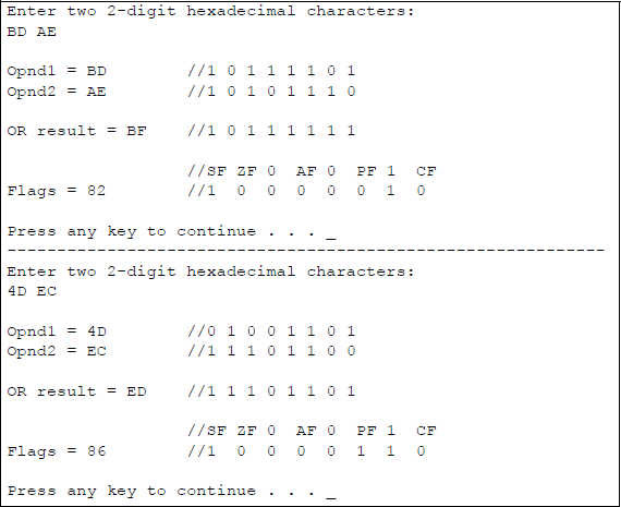
Program to illustrate the logical OR operation and resulting flags: (a) the program and (b) the outputs.
8.3 Logical Exclusive-OR Instruction
The XOR instruction performs the bitwise exclusive-OR operation of two operands — the first operand (destination) and the second operand (source) and stores the result in the destination operand. The source operand can be located in a general-purpose register, in memory, or can be an immediate operand. The destination operand can be in a general-purpose register or a memory location; however, both operands cannot be in memory. The syntax for the logical XOR instruction is shown below.
XOR register/memory, register/memory/immediate
The truth table for the exclusive-OR function is shown in Table 8.5. The variables x1 , x2 , and z1 represent a bit in the destination operand, a bit in the source operand, and the resulting bit in the destination operand, respectively. The XOR instruction can be used to invert select bits; that is, to change a bit with a value of 1 to a value of 0 and vice versa, because any bit that is exclusive-ORed with a 1 bit will invert the value of the bit. The affected flags are the parity flag (PF), the sign flag (SF), and the zero flag (ZF) — the overflow flag (OF) and the carry flag (CF) are set to 0. Examples of the exclusive-OR function are shown in Table 8.6(a) and Table 8.6(b). Table 8.6(b) inverts all bits regardless of their original value.
Examples of the XOR Function for Eight Bits
XOR |
||||||||||||||||
|---|---|---|---|---|---|---|---|---|---|---|---|---|---|---|---|---|
1 |
1 |
0 |
1 |
0 |
0 |
1 |
0 |
1 |
0 |
0 |
1 |
0 |
1 |
1 |
0 |
|
1 |
0 |
1 |
1 |
1 |
0 |
1 |
1 |
1 |
1 |
1 |
1 |
1 |
1 |
1 |
1 |
|
0 |
1 |
1 |
0 |
1 |
0 |
0 |
1 |
0 |
1 |
1 |
0 |
1 |
0 |
0 |
1 |
|
(a) |
(b) |
|||||||||||||||
There is no exclusive-NOR instruction; however, this function can be achieved by using the XOR operation in conjunction with the NOT operation (Section 8.4) to invert the result. Figure 8.4 contains an assembly language module embedded in a C program that illustrates the logical XOR function of two operands. The program displays the result of the XOR operation together with the resulting flags.
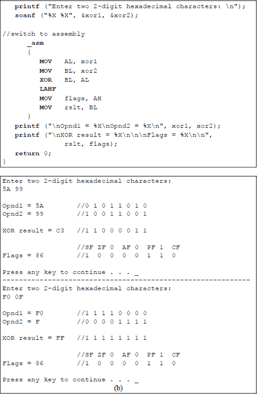
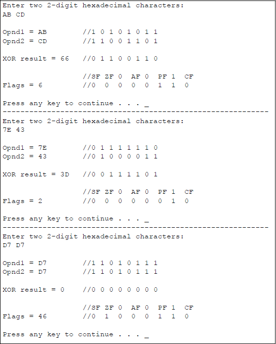
Program to illustrate the logical XOR operation and resulting flags: (a) the program and (b) the outputs.
8.4 Logical NOT Instruction — 1s Complement
The NOT instruction performs a bitwise 1s complement operation on the destination operand and stores the result in the destination operand. The destination can be a general-purpose register or a memory location. The NOT instruction inverts each bit in the destination operand and is also referred to as the diminished-radix complement (or the r – 1 complement). The syntax for the NOT instruction is shown below.
NOT register/memory
Operands that are represented in the 1s complement notation are signed numbers with the following range:
The truth table for the NOT function is shown in Table 8.7. The variables x1 and z1 represent bits in the destination operand and the resulting bit in the destination operand, respectively. No flags are affected by the NOT instruction.
The binary number 11012 will be 1s complemented. The number has a decimal value of – 2. To obtain the 1s complement, subtract each digit in turn from 1 (the highest number in the radix), as shown below — or for radix 2, simply invert each bit. Therefore, the 1s complement of 11012 is 00102, which has a decimal value of + 2.
To verify the operation, add the negative and positive numbers to obtain 11112, which is zero in 1s complement notation; 00002 is also zero in 1s complement.
8.5 NEG Instruction — 2s Complement
The NEG instruction performs a 2s complement operation on the destination operand and stores the result in the destination operand. The destination can be a general-purpose register or a memory location. The NEG instruction subtracts the destination operand from zero, effectively changing the sign of the number while maintaining the same absolute value.
The value of a positive number in 2s complement representation is obtained in the usual manner by adding the values of the 1 bits by the weight of their respective positions. The value of a negative number in 2s complement representation is obtained by adding the values of the 0 bits by weight in their respective positions and then adding a value of one to the result.
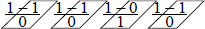
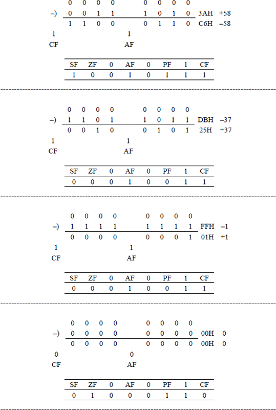
Another method of obtaining the 2s complement of a number is to form the 1s complement of the number, then add one to the result. Both methods are shown Figure 8.5 using 4-bit operands. Figure 8.5(a) subtracts the operand from zero; Figure 8.5(b) adds one to the 1s complement.
Methods to obtain the 2s complement (negation) of a number: (a) subtract from zero and (b) add 1 to the 1s complement.
A third method to generate the radix complement for a radix 2 number is to keep the low-order 0s and the first 1 unchanged, then complement (invert) the remaining high-order bits.
The NEG instruction is also referred to as the radix complement (or the r complement). The syntax for the NEG instruction is shown below.
NEG register/memory
A integer has the following range in 2s complement representation, where the number zero is considered to be positive:
A positive number A is represented as
and a negative number is represented as
where A′ is the diminished-radix complement. Thus, the radix complement is obtained by adding 1 to the diminished-radix complement; that is, (r – 1) + 1 = r.
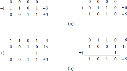
The flags affected by the NEG instruction are the overflow flag (OF), the sign flag (SF), the zero flag (ZF), the auxiliary carry flag (AF), the parity flag (PF), and the carry flag (CF) — if the operand is zero, then CF = 0. Figure 8.6 shows an assembly language module embedded in a C program that illustrates both the NOT instruction and the NEG instruction and the associated flags for the NEG instruction.
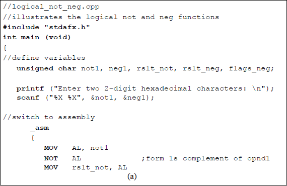
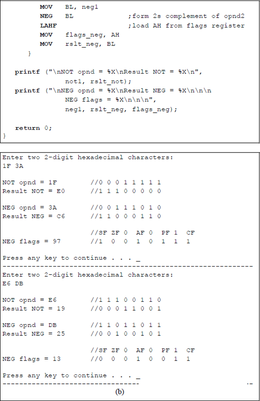
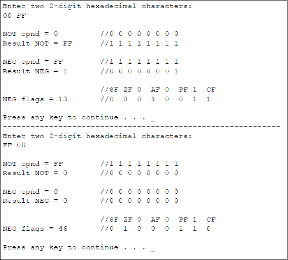
Program to illustrate the logical NOT and NEG operations and resulting flags for the NEG function: (a) the program and (b) the outputs.
To obtain the NOT function of an operand, the bits are simply inverted. The NEG results for the operands shown in Figure 8.6(b) are determined by the calculations shown in Figure 8.7, which subtracts the operands from a value of zero. It was previously stated that the NEG instruction subtracts the destination operand from zero, effectively changing the sign of the number while maintaining the same absolute value. The rules for subtraction in radix 2 are as follows:
0 – 0 |
= |
0 |
|
0 – 1 |
= |
1 |
with a borrow from the next higher-order minuend |
1 – 0 |
= |
1 |
|
1 – 1 |
= |
0 |
8.6 TEST and Set Byte on Condition Instructions
The TEST instruction and the set byte on condition (SETcc) instruction can be used to alter the program flow depending on the state of the EFLAGS register. The TEST instruction can be followed by a jump on condition (Jcc) instruction.
8.6.1 TEST Instruction
The TEST instruction performs the logical AND operation of two operands on a bit-by-bit basis. The result of the operation affects the sign flag (SF), the zero flag (ZF), and the parity flag (PF) in a manner similar to an AND instruction; however, the destination and source operands are not changed. The result of the AND operation is discarded after execution of the TEST instruction. The syntax for the TEST instruction is shown below.
TEST register/memory, register/immediate
If any identical bit positions in the two operands both contains 1s, then the zero flag is reset. The state of the EFLAGS register can then be tested by using the jump on condition (Jcc) instruction, the loop on condition (LOOPcc), or the set byte on condition (SETcc) instruction. For example, the low-order four bits in register AX can be tested to determine if any bits are nonzero, as shown below. The jump will occur if the zero flag is reset (ZF = 0).
TEST AX, 0000000000001111
JNZ N0N_ZERO
8.6.2 Set Byte on Condition (SETcc) Instruction
The set byte on condition (SETcc) instruction sets the destination byte operand to a value of 0 or 1 depending on the state of certain flags in the EFLAGS register. The syntax for the SETcc instruction is shown below.
SETcc register/memory
The affected flags are similar to those of the jump on condition (Jcc) instruction described in Chapter 6. An example to determine if register EAX is greater than register EBX is shown below. If register EAX is greater than register EBX, then register CH is set to a value of 00000001.
CMP EAX, EBX
SETG CH
8.7 Bit Test Instructions
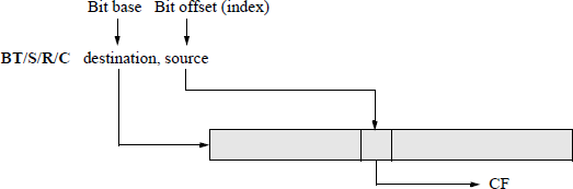
The bit test instructions operate on a single bit and are used to scan the bits in an operand and then perform an operation on the selected bit. The operand that contains the bit to be tested is specified by the destination operand (first operand — or bit base), which can be in a general-purpose register of a memory location. The location of the bit to be tested is stipulated by the source operand (bit offset). The location of the bit in the bit string is specified as an offset from bit 0 of the string. The selected bit is then stored in the carry flag (CF). No other flags are affected.
If the destination operand indicates a register, then the instruction assumes mod-ulo-16, modulo-32, or modulo-64 of the source operand, depending on the size of the operand and the mode. Operands that are 64 bits can be used only in 64-bit mode. If the destination operand is a memory location, then this specifies the address of a byte in memory that contains the operand on which the bit test instruction is to be executed. The syntax for the bit test instructions is shown below.
BT/S/R/C register/memory, register/immediate
There are four bit test instructions that will be discussed in this section: bit test (BT), bit test and set (BTS), bit test and reset (BTR), and bit test and complement (BTC). Figure 8.8 shows a general diagram that illustrates the four bit test instructions.
8.7.1 Bit Test (BT) Instruction
Figure 8.9 shows a drawing for the bit test (BT) instruction using a general-purpose register and an immediate operand. The base offset is modulo-32, because register EAX is 32 bits. If the immediate value is greater than 31, then it is modulo-32. For example, if the offset were 198, then bit 6 would be selected.
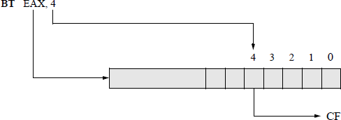
The BT instruction copies the value of the selected bit within a bit string to the CF flag; the sequence of bits in a general-purpose register or a memory location are numbered from the low-order bit to the high-order bit. If the destination operand is in memory, then the processor can access two bytes beginning with a 16-bit operand address or four bytes beginning with a 32-bit operand address.
8.7.2 Bit Test and Set (BTS) Instruction
The bit test and set (BTS) instruction stores the selected bit in the carry flag (CF), then sets the selected bit in the bit string (destination) to a value of 1. The destination operand (bit base) can be a general-purpose register or a memory location, both of which can be 16 bits, 32 bits, or 64 bits. The source operand (bit offset — or index) can be a register or an immediate operand. If the index is an immediate operand, then the selected bit can range from 0 to 31 or greater, depending on the mode. The general comments and figures for the BT instruction also apply to the BTS instruction.
8.7.3 Bit Test and Reset (BTR) Instruction
The bit test and reset (BTR) instruction selects a single bit in a bit string specified by the destination operand (bit base) and stores the selected bit in the carry flag (CF), then resets the selected bit in the bit string (destination) to a value of 0. The selected bit is determined by the source operand (bit offset — or index). The destination operand can be a general-purpose register or a memory location, both of which can be 16 bits, 32 bits, or 64 bits. The source operand can be a register or an immediate operand. If the index is an immediate operand, then the selected bit can range from 0 to 31 or greater, depending on the mode. The general comments and figures for the BT instruction also apply to the BTR instruction.
8.7.4 Bit Test and Complement (BTC) Instruction
The bit test and complement (BTC) instruction selects a single bit in a bit string specified by the destination operand (bit base) and stores the selected bit in the carry flag (CF), then complements (inverts) the selected bit in the bit string (destination). The selected bit is determined by the source operand (bit offset — or index). The destination operand can be a general-purpose register or a memory location, both of which can be 16 bits, 32 bits, or 64 bits. The source operand can be a register or an immediate operand. If the index is an immediate operand, then the selected bit can range from 0 to 31 or greater, depending on the mode. The general comments and figures for the BT instruction also apply to the BTC instruction.
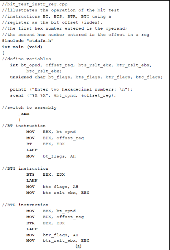
Figure 8.10 shows an assembly language module embedded in a C program that illustrates the four bit test instructions using immediate data as the bit offset. An 8-character hexadecimal number is entered from the keyboard and stored in the variable bt_opnd to be used as the bit test operand. The results of the bit test operations are displayed as: bt_opnd for the BT instruction, bts_rslt_ebx for the BTS instruction, btr_rslt_ebx for the BTR instruction, btc_rslt_ebx for the BTC instruction, and btc_rslt_mod32 for the BTC instruction in which the bit index is greater than 31.
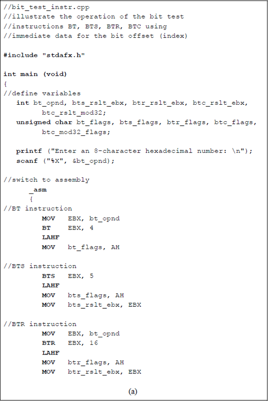
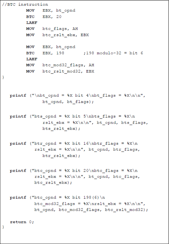
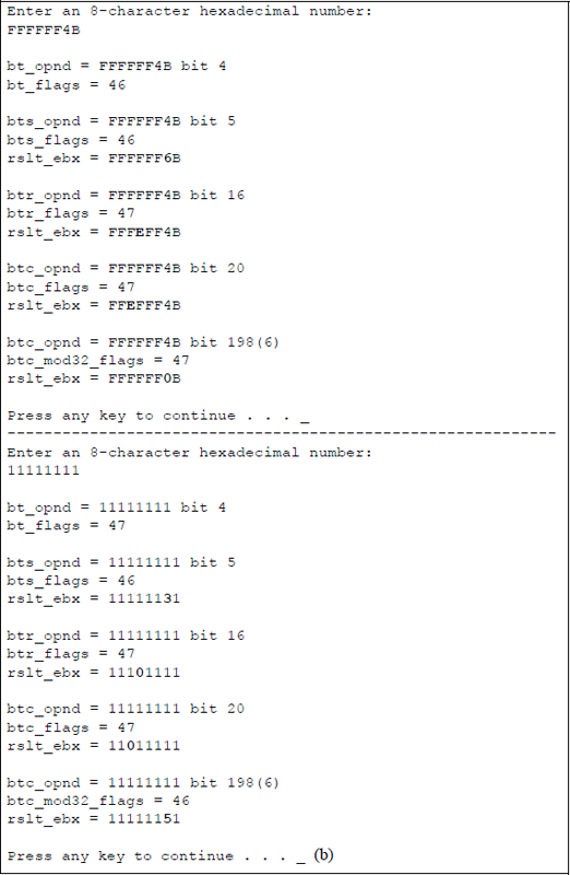
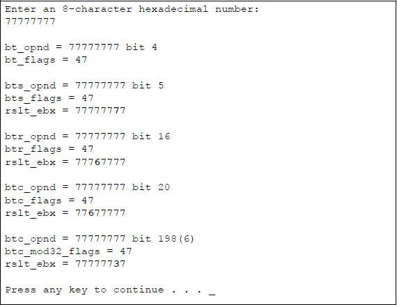
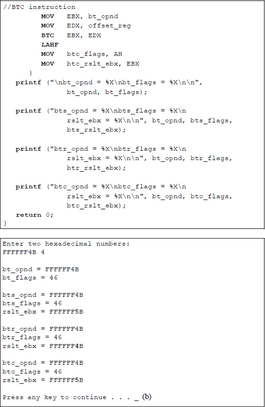
Program to illustrate the bit test instructions: BT, BTS, BTR, and BTC using immediate data as the bit offset: (a) the program and (b) the outputs.
The flags are also displayed for each bit test instruction as: bt_flags for the BT instruction, bts_flags for the BTS instruction, btr_flags for the BTR instruction, btc_flags for the BTC instruction, and btc_mod32_flags for the BTC instruction in which the bit index is greater than 31. Since the carry flag (CF) is the only flag affected by the bit test instructions, the state of the other flags is irrelevant.
The LAHF instruction is executed for each bit test instruction; register AH is then stored in the appropriate flags variable. The second BTC instruction has a bit offset (index) value of 198. This establishes the selected bit as bit 6, because 198 modulo-32 is 6.
In the first pass, the hexadecimal number of FFFFFF4B (shown below) is entered from the keyboard and stored in the bt_opnd variable. Then the BT instruction moves bit 4 (0) to the carry flag and leaves the original bit 4 unchanged.
31 |
... |
23 |
22 |
21 |
20 |
... |
17 |
16 |
... |
7 |
6 |
5 |
4 |
3 |
2 |
1 |
0 |
|---|---|---|---|---|---|---|---|---|---|---|---|---|---|---|---|---|---|
1 |
1 |
1 |
1 |
1 |
1 |
1 |
1 |
1 |
0 |
1 |
0 |
0 |
1 |
0 |
1 |
1 |
The BTS instruction operates on bit 5 (0) of the bt_opnd variable, moves bit 5 to the carry flag, then sets the original bit 5, giving the four bits 4 through 7 a value of 616. The BTR instruction operates on bit 16 (1) of the bt_opnd variable, moves bit 16 to the carry flag, then resets the original bit 16, giving the four bits 16 through 19 a value of E16 (1410). The first BTC instruction operates on bit 20 (1) of the bt_opnd variable, moves bit 20 to the carry flag, then complements bit 20 to yield a value of 0, giving the four bits 20 through 23 a value of E16 (1410). The second BTC instruction operates on bit 6 (198 modulo-32) of the bt_opnd variable, moves bit 6 to the carry flag, then complements bit 6 to yield a value of 0, giving the four bits 4 through 7 a value of 0. A similar sequence occurs for the two remaining user-entered hexadecimal numbers: 11111111 and 77777777.
Figure 8.11 shows an assembly language module embedded in a C program that illustrates the four bit test instructions using data in register EDX as the bit offset. An 8-character hexadecimal number is entered from the keyboard and stored in the variable bt_opnd to be used as the bit test operand. Then a hexadecimal number is entered as the bit offset and stored in the variable offset_reg, which is later stored in register EDX.
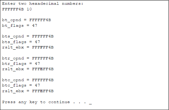
Program to illustrate the bit test instructions: BT, BTS, BTR, and BTC using the contents of register EDX as the bit offset: (a) the program and (b) the outputs.
This program is similar to the program shown in Figure 8.10, except that the bit offset is in a register rather than specified as immediate data. The hexadecimal number that is entered as the bit offset applies to all of the bit test instructions. The second set of characters shown in Figure 8.11(b) is hexadecimal FFFFFF4B for the bit test operand and hexadecimal 10 (1610) for the bit offset. Bit offsets greater than 31 are not shown in this example.
The results of the four bit test operations are displayed together with the corresponding flags in a manner identical to that of Figure 8.10. Unlike the program of Figure 8.10 however, the bit test and set (BTS) instruction does not reinitialize the bit test operand in register EBX, because the contents were not changed by the bit test (BT) instruction.
8.8 Bit Scan Instructions
There are two bit scan instructions: bit scan forward (BSF) and bit scan reverse (BSR). These instructions scan the contents of a register or memory location to determine the location of the first 1 bit in the operand. If the scanned operand contains all zeroes, the zero flag (ZF) is set to 1; if the scanned operand contains at least one 1 bit, then the ZF flag is reset — the other flags are undefined. The syntax for the bit scan instructions is shown below.
BSF/R register, register/memory
8.8.1 Bit Scan Forward (BSF) Instruction
The BSF instruction scans the source operand in a register or memory location to determine the location of the first 1 bit with reference to bit 0 of the operand. The operation scans the source operand from the low-order bit to the high-order bit. Scanning stops when the first low-order 1 bit is encountered. If a 1 bit is found, then its location is specified as the bit index (offset) and is stored in the destination register. The bit index is an unsigned offset referenced from bit 0. If the source operand is zero, then the ZF flag is set to 1 and the contents of the destination register are undefined. Figure 8.12 illustrates a BSF operation using register EAX as the destination register.
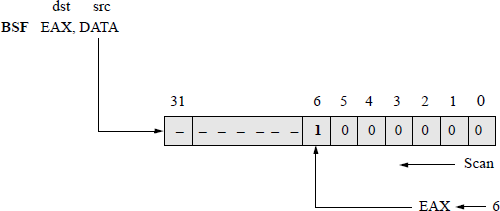
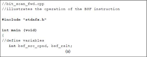
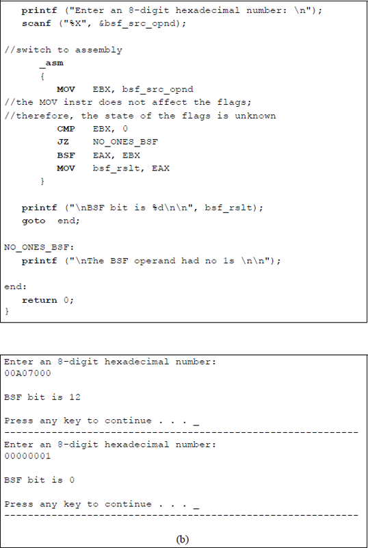
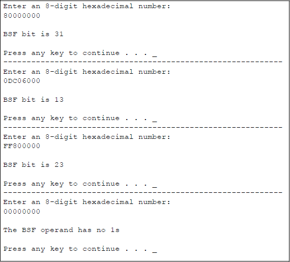
Figure 8.13 shows an assembly language module embedded in a C program that illustrates the operation of the BSF instruction. An 8-digit hexadecimal number is entered from the keyboard and moved to register EBX. Since the MOV instruction does not affect the flags, the operand in register EBX is first compared to zero to determine if there are any 1s in the operand. Then a conditional jump if zero (JZ) instruction is executed — the jump will occur if the ZF flag is set, indicating no 1s in the operand. If the jump does not occur, then register EBX is scanned from bit 0 to bit 31 to locate the position of the first 1 bit. The operand and the location of the first low-order 1 bit are then displayed.
8.8.2 Bit Scan Reverse (BSR) Instruction
The BSR instruction scans the source operand in a register or memory location to determine the location of the first 1 bit with reference to bit 0 of the operand. The operation scans the source operand from the high-order bit to the low-order bit. Scanning stops when the first high-order 1 bit is encountered. If a 1 bit is found, then its location is specified as the bit index (offset) and is stored in the destination register. The bit index is an unsigned offset referenced from bit 0. If the source operand is zero, then the ZF flag is set to 1 and the contents of the destination register are undefined. Figure 8.12 also applies to the BSR instruction, except that scanning is done from left to right — from bit 31 to bit 0.
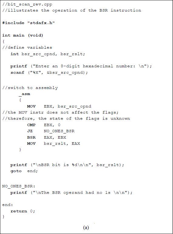
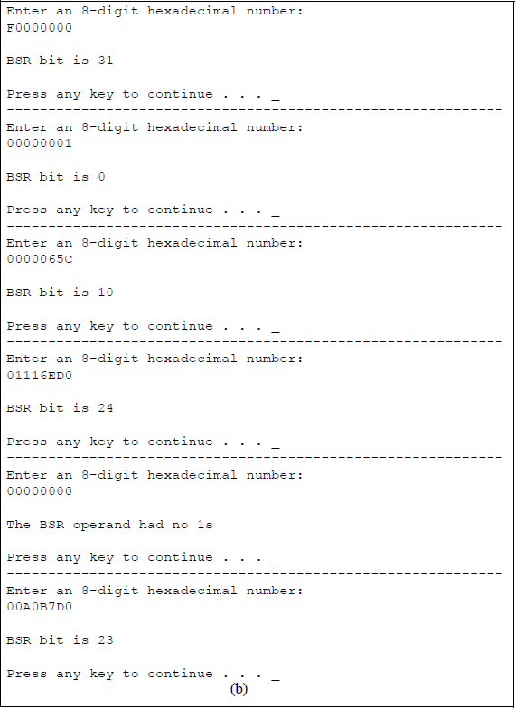
Figure 8.14 shows an assembly language module embedded in a C program that illustrates the operation of the BSR instruction. An 8-digit hexadecimal number is entered from the keyboard and is scanned from bit 31 to bit 0 to locate the position of the first 1 bit. The operand and the location of the first high-order 1 bit are displayed.
8.9 Shift Instructions
There are six shift instructions: shift arithmetic left (SAL), shift logical left (SHL), shift arithmetic right (SAR), shift logical right (SHR), shift left double (SHLD), and shift right double (SHRD). The SAL and SAR instructions perform arithmetic shifts where the operands are signed numbers in 2s complement representation. The SHL and SHR instructions perform logical shifts on unsigned numbers. The SHLD and SHRD instructions perform shifts from one operand to another operand. The syntax for these instructions is shown below.
SAL/R/SHL/R register/memory, immediate/register CL
SHLD/SHRD register/memory, register, immediate/register CL
8.9.1 Shift Arithmetic Left (SAL) Instruction
The bits in the first operand (destination) are shifted left by the number of bits specified by the second operand (count). The count can be an immediate value of 1, an immediate value specified in a byte, or a count in register CL. The count is masked by 1F16 (000111112) so that the count cannot exceed a count of 31 (modulo-32), making the count range from 0 to 31. If the REX prefix is used in 64-bit mode, then the count is masked to produce a range from 0 to 63. In this mode, the number of general-purpose registers is increased from eight to sixteen and can be extended to 64 bits.
During each shift, the high-order bit of the destination is shifted into the carry flag (CF) and a 0 is shifted into the low-order bit. Since the destination operand is a signed number in 2s complement representation, an overflow occurs if the high-order bit of the destination is not equal to the carry flag. This means that significant bits have been lost in the destination operand.
The flags affected by the SAL instruction are the overflow flag (OF), the sign flag (SF), the zero flag (ZF), the parity flag (PF), and the carry flag (CF). These flags reflect the result of the SAL instruction execution. The overflow flag (OF) is not affected by multiple-bit shifts; it is affected only by single-bit shifts. If the initial count is greater than 1, then the overflow flag (OF) is undefined. The OF flag is reset (0) if the high-order bit in the destination is the same as the CF flag after an initial count of 1 has been performed; if these bits are different, then the OF flag is set (1).
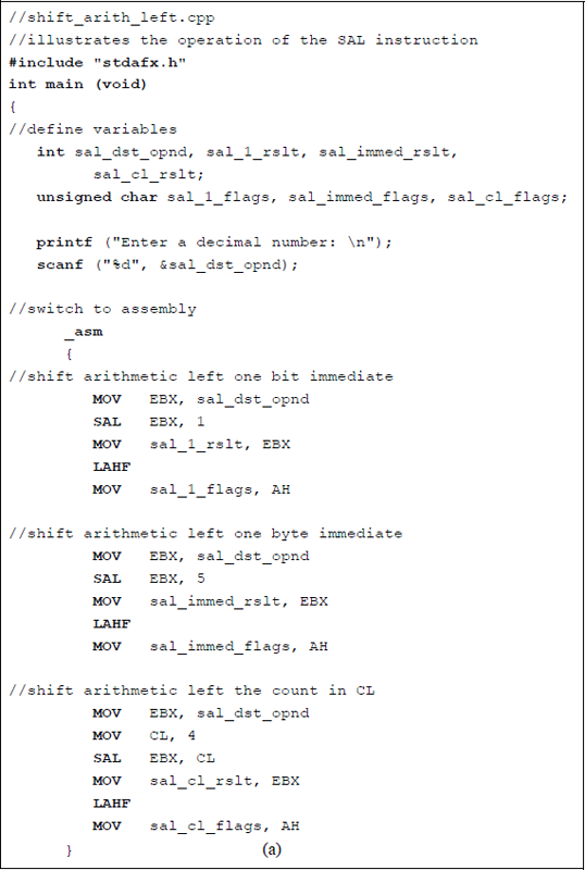
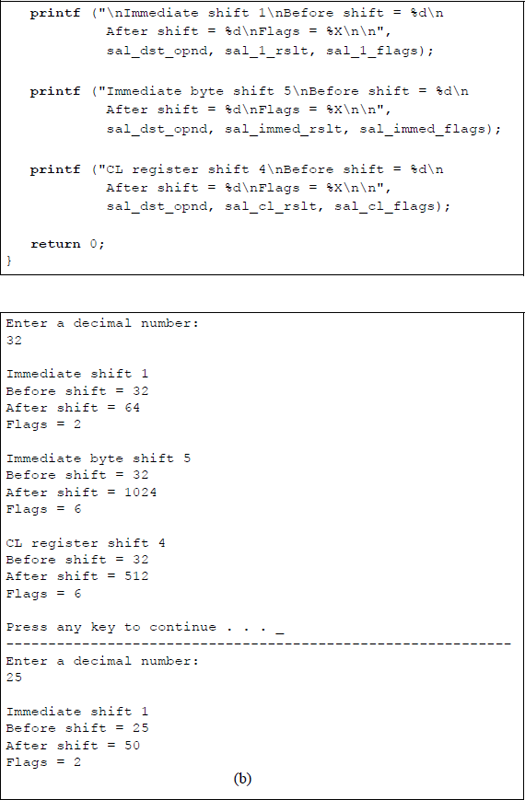
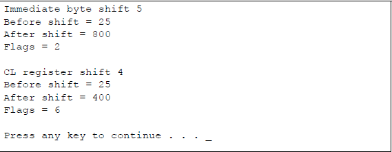
Figure 8.15 shows an assembly language module embedded in a C program that illustrates the use of the SAL instruction utilizing a shift count with an immediate value of 1, a shift count with an immediate byte of 5, and a shift count contained in register CL. The original shift operand is shown in the outputs before execution of the SAL instruction and the resulting shifted operand after execution of the SAL instruction. The flags are also shown that reflect the result of the operation.
8.9.2 Shift Logical Left (SHL) Instruction
The SAL instruction and the SHL instruction are equivalent operations, although the SHL instruction is for unsigned operands. They both shift the destination operand left toward the high-order bit position, which is shifted into the carry flag. Zeroes are shifted into the low-order bit position. The SAL and the SHL instructions are equivalent to a multiply operation: a left shift of one bit multiplies the operand by two; a left shift of three bits multiplies the operand by eight. Operations are shown below using eight bits for both the SAL instruction (2s complement) and the SHL instruction.
SAL: |
Initial operand = |
0 |
0 |
0 |
1 |
1 |
0 |
1 |
1 |
+27 |
SAL 1 (×2) |
0 |
0 |
1 |
1 |
0 |
1 |
1 |
0 |
+54 |
|
SAL: |
Initial operand = |
0 |
0 |
0 |
0 |
1 |
1 |
1 |
1 |
+15 |
SAL 3 (×8) |
0 |
1 |
1 |
1 |
1 |
0 |
0 |
0 |
+120 |
|
SAL: |
Initial operand = |
1 |
1 |
1 |
0 |
0 |
0 |
1 |
1 |
–29 |
SAL 2 (×4) |
1 |
0 |
0 |
0 |
1 |
1 |
0 |
0 |
–116 |
|
SHL: |
Initial operand = |
0 |
0 |
0 |
0 |
0 |
1 |
1 |
1 |
7 |
SHL 4 (×16) |
0 |
1 |
1 |
1 |
0 |
0 |
0 |
0 |
112 |
|
SHL: |
Initial operand = |
0 |
0 |
0 |
1 |
1 |
1 |
1 |
1 |
31 |
SHL 3 (×8) |
1 |
1 |
1 |
1 |
1 |
0 |
0 |
0 |
248 |
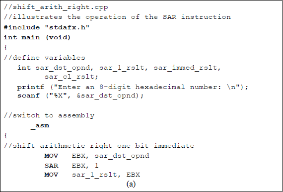
8.9.3 Shift Arithmetic Right (SAR) Instruction
The bits in the first operand (destination) are shifted right by the number of bits specified by the second operand (count). The count can be an immediate value of 1, an immediate value specified in a byte, or a count in register CL. The count is masked by 1F16 (000111112) so that the count cannot exceed a count of 31 (modulo-32), making the count range from 0 to 31. If the REX prefix is used in 64-bit mode, then the count is masked to produce a range from 0 to 63. In this mode, the number of general-purpose registers is increased from eight to sixteen and can be extended to 64 bits.
For each bit shift, the low-order bit (0) is shifted into the carry flag. The highorder bit — the sign bit of the destination operand — extends to the right replacing the bits that have been shifted, thereby keeping the sign of the number unchanged.
The flags affected by the SAR instruction are the overflow flag (OF), the sign flag (SF), the zero flag (ZF), the parity flag (PF), and the carry flag (CF). These flags reflect the result of the SAR instruction execution. The overflow flag (OF) is not affected by multiple-bit shifts; it is affected only by single-bit shifts. The OF flag is reset (0) for all 1-bit shifts.
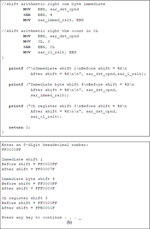
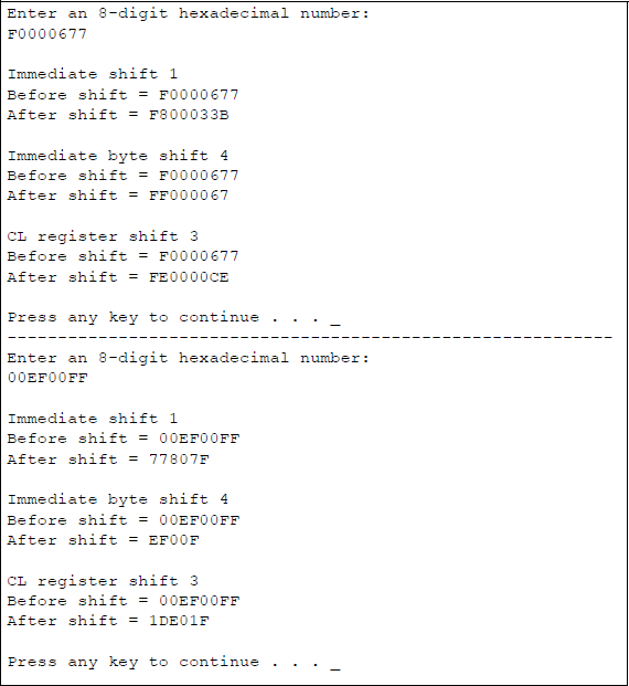
Figure 8.16 shows an assembly language module embedded in a C program that illustrates the use of the SAR instruction utilizing a shift count with an immediate value of 1, a shift count with an immediate byte of 4, and a shift count contained in register CL. The original operand is shown in the outputs before execution of the SAR instruction and the resulting shifted operand after execution of the SAR instruction.
8.9.4 Shift Logical Right (SHR) Instruction
The SHR instruction shifts an unsigned operand right the number of bits specified in the count field of the second operand, which can be an immediate value of 1, an immediate value specified in a byte, or a value in the CL register. During each shift operation, the low-order bit is shifted into the carry flag and a zero is shifted into the highorder bit position. The SAR instruction and the SHR instruction can be used to divide the destination operand by powers of 2. A right shift of one bit divides the operand by two; a right shift of three bits divides the operand by eight. Operations are shown below using eight bits for both the SAR instruction (2s complement) and the SHR instruction.
SAR: |
Initial operand = |
0 |
0 |
0 |
1 |
0 |
1 |
0 |
0 |
+20 |
SAR 1 (÷2) |
0 |
0 |
0 |
0 |
1 |
0 |
1 |
0 |
+10 |
|
SAR: |
Initial operand = |
0 |
1 |
1 |
0 |
1 |
0 |
0 |
0 |
+104 |
SAR 3 (÷8) |
0 |
0 |
0 |
0 |
1 |
1 |
0 |
1 |
+13 |
|
SAR: |
Initial operand = |
1 |
1 |
1 |
0 |
0 |
1 |
1 |
0 |
–26 |
SAR 2 (÷4) |
1 |
1 |
1 |
1 |
1 |
0 |
0 |
1 |
–7 |
|
SAR: |
Initial operand = |
0 |
0 |
0 |
1 |
0 |
1 |
0 |
1 |
+21 |
SAR 1 (÷2) |
0 |
0 |
0 |
0 |
1 |
0 |
1 |
0 |
+10 |
|
SAR: |
Initial operand = |
0 |
0 |
0 |
1 |
0 |
1 |
0 |
1 |
+21 |
SAR 2 (÷4) |
0 |
0 |
0 |
0 |
0 |
1 |
0 |
1 |
+5 |
|
SHR: |
Initial operand = |
0 |
0 |
1 |
1 |
0 |
0 |
0 |
0 |
48 |
SHR 4 (÷16) |
0 |
0 |
0 |
0 |
0 |
0 |
1 |
1 |
3 |
|
SHR: |
Initial operand = |
1 |
0 |
0 |
1 |
1 |
0 |
0 |
0 |
152 |
SHR 3 (÷8) |
0 |
0 |
0 |
1 |
0 |
0 |
1 |
1 |
19 |
Note the result of the third SAR instruction, which divides –26 by 4. The shift operation leaves an incorrect result; however, the last bit shifted out of the operand — the most significant bit (1) from position 21 — is stored in the carry flag. This problem occurs only for negative numbers. A signed division of these two numbers yields a correct result with a quotient and remainder. In the fourth SAR instruction, +21 is divided by 2, which yields a result of 10 with the carry flag (CF) = 1; that is, an answer of 10.5. In the fifth SAR instruction, +21 is divided by 4, which yields a result of 5 with the carry flag (CF) = 0. If the two bits shifted out are considered, then the result would be 0000 0101.01 (+5.25), which is correct.
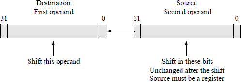
8.9.5 Shift Left Double (SHLD) Instruction
The SHLD instruction is a 3-operand instruction that is used to shift bits from one operand into another operand. Bits from the second operand (source operand) are shifted left into the first operand (destination operand). The number of bits shifted are specified in a count variable that is either an unsigned immediate integer or a count in register CL. Bits are shifted from the source operand, beginning with the high-order bit position, into the destination operand, beginning with the low-order bit position. The destination operand is either a register or a memory location; the source operand must be a register and is not modified by the instruction. For convenience, the syntax for the SHLD instruction is reproduced below.
SHLD register/memory, register, immediate/register CL
Both the destination operand and the source operand must be the same length, either 16 bits or 32 bits. The count in register CL is masked by 1F16 (000111112) so that the count cannot exceed a count of 31, making the count range from 0 to 31. A count that is greater than the size of the operand produces a result that is undefined. If the REX prefix is used in 64-bit mode, then the count is masked to produce a range from 0 to 63. In this mode, the number of general-purpose registers is increased from eight to sixteen and can be extended to 64 bits.
The carry flag (CF) contains the last bit that is shifted out of the destination operand. If the shift count is 1, then the overflow flag (OF) is set (1) if a change in the sign occurred; otherwise, it is reset (0); for counts greater than one, the overflow flag is undefined. A count of zero does not affect the flags.
Figure 8.17 shows a diagram that illustrates the operation of the SHLD instruction for two 32-bit operands. Figure 8.18 shows a code segment that demonstrates the SHLD instruction using two operands from memory that are moved to register EAX (destination) and to register EBX (source). The shift count is an immediate value of seven.
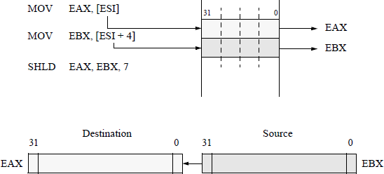
Code segment and register initialization of operands from memory for a SHLD instruction.
Figure 8.19 shows a numerical example of the SHLD instruction using registers AX (destination) and register BX (source). Register AX is assigned a value of 1234H and register BX is assigned a value of 5678H. The source operand in register BX is saved before the shift operation begins so that it can be restored after the SHLD instruction is finished.
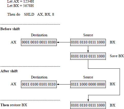
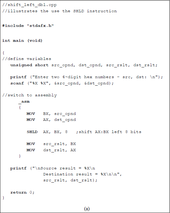
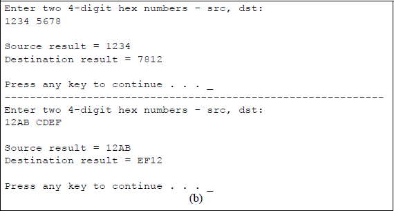
Figure 8.20 shows an assembly language module embedded in a C program that illustrates the application of the SHLD instruction shown in Figure 8.19 using the AX and BX general-purpose registers. The unsigned short integer data type is used to characterize the 16-bit unsigned hexadecimal numbers. This data type consists of two bytes with a range from 0 to 65,535.
8.9.6 Shift Right Double (SHRD) Instruction
The SHRD instruction functions in a manner similar to the SHLD instruction, except that the bits are shifted to the right from the low-order bit position of the source operand register to the high-order bit of the destination operand (register/memory). The number of bits shifted is specified in a count variable that is either an unsigned immediate integer or a count in register CL. The syntax for the SHRD instruction is shown below.
SHLD register/memory, register, immediate/register CL
Both the destination operand and the source operand must be the same length, either a word (16 bits) or a doubleword (32 bits). The count is masked by 1F16(000111112) providing a count range from 0 to 31. A count that is greater than the size of the operand produces an undefined result.
If the REX prefix is used in 64-bit mode, then the count is masked to produce a range from 0 to 63. In this mode, the number of general-purpose registers is increased from eight to sixteen and can be extended to 64 bits. The last bit shifted out of the destination operand is stored in the carry flag (CF). The overflow flag (OF) is set if the sign changes for a 1-bit shift; otherwise, the overflow flag is reset. The states of the sign flag (SF), the zero flag (ZF), and the parity flag (PF) are determined by the result of the shift operation. Figure 8.21 shows a diagram that illustrates the operation of the SHRD instruction for two 32-bit operands. The source operand is unchanged after the shift operation.
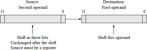
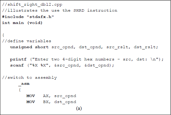
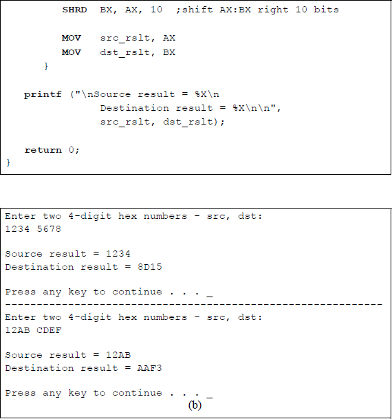
Figure 8.22 shows an assembly language module embedded in a C program that illustrates the application of the SHRD instruction using the AX and BX general-purpose registers for the source operand and destination operand, respectively. Two 4-digit hexadecimal numbers are entered from the keyboard and displayed together with the source operand result and the destination operand result. The unsigned short integer data type is used to characterize the 16-bit unsigned hexadecimal numbers.
8.10 Rotate Instructions
This section describes the four rotate instructions: rotate left (ROL), rotate through carry left (RCL), rotate right (ROR), and rotate through carry right (RCR). The rotate instructions rotate the bits in the destination operand a specific number of bits as stipulated in the count field of the second operand. The count can be a single bit shift, an unsigned integer as an immediate byte, or a count in register CL. The count is masked by 1F16 (000111112) providing a count range from 0 to 31. The shift operations presented in Section 8.9 resulted in an inherent loss of bits; however, the rotate instructions provide a result in which no bits are lost — they are simply shifted in to the other end of the destination operand. The syntax for the rotate instructions is shown below.
ROL/RCL/ROR/RCR register/memory, immediate/register CL
8.10.1 Rotate Left (ROL) Instruction
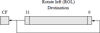
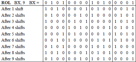
The rotate left (ROL) instruction rotates (shifts) the destination bits left toward the high-order bit position of the operand. The high-order bit is shifted into the carry flag and also into the low-order bit position. The carry flag is not included as part of the destination result. The overflow flag (OF) is set for shifts of one bit only and is undefined for all other shift counts. The overflow flag is defined as the exclusive-OR of the carry flag and the high-order bit of the result; that is, a change of sign occurred for the destination operand. Figure 8.23 shows a diagram that illustrates the operation of the ROL instruction. Figure 8.24 provides a numerical example for a ROL instruction using general-purpose register BX with a rotate count of 9.
8.10.2 Rotate through Carry Left (RCL) Instruction
The rotate through carry left (RCL) instruction is similar to the ROL instruction except that the carry flag is included in the rotation. The RCL instruction shifts the carry flag into the low-order bit position of the destination operand and shifts the highorder bit of the destination into the carry flag. The overflow flag operates in an identical manner as in the ROL instruction. Figure 8.25 shows a diagram that illustrates the operation of the RCL instruction. Figure 8.26 provides a numerical example for a RCL instruction using general-purpose register EAX with a rotate count of 4 in which the carry flag is initially set to a value of 1. This example depicts one of the user-entered inputs in an assembly language program that is described below.
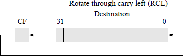
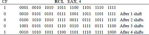
Figure 8.27 shows an assembly language module embedded in a C program that illustrates the application of the ROL instruction and the RCL instruction using the general-purpose register EAX as the destination operand. An 8-digit hexadecimal number is entered from the keyboard and displayed together with the resulting destination operand. The set carry flag (STC) instruction is introduced in the program to set the carry flag to a known state in order to execute the RCL instruction. The STC instruction sets the carry flag in the EFLAGS register to a value of 1. There are two similar instructions: clear carry flag (CLC), which resets the carry flag, and the complement carry flag (CMC), which changes the state of the carry flag — from 0 to 1 or from 1 to 0.
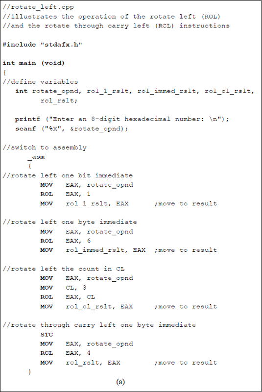
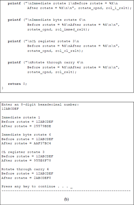
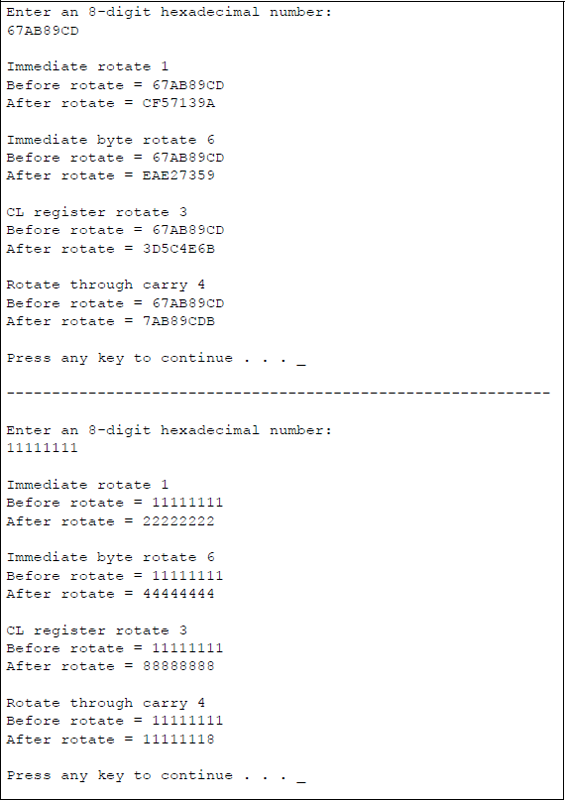
Program to illustrate the application of the ROL and the RCL instructions: (a) the program and (b) the outputs.
8.10.3 Rotate Right (ROR) Instruction
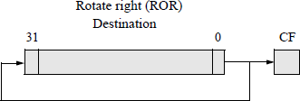
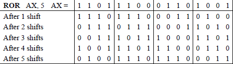
The rotate right (ROR) instruction rotates (shifts) the destination bits right toward the low-order bit position of the operand. The low-order bit is shifted into the carry flag and also into the high-order bit position. The carry flag is not included as part of the destination result. The overflow flag (OF) is set for shifts of one bit only and is undefined for all other shift counts. The overflow flag is defined as the exclusive-OR of the two high-order bits of the result; that is, a change of sign occurred for the destination operand. Figure 8.28 shows a diagram that illustrates the operation of the ROR instruction. Figure 8.29 shows a numerical example for a ROR instruction using general-purpose register AX with a rotate count of 5.
8.10.4 Rotate through Carry Right (RCR) Instruction
The rotate through carry right (RCR) instruction is similar to the ROR instruction except that the carry flag is included in the rotation. The RCR instruction shifts the carry flag into the high-order bit position of the destination operand and shifts the low-order bit of the destination into the carry flag. The overflow flag operates in an identical manner as in the ROR instruction. Figure 8.30 shows a diagram that illustrates the operation of the RCR instruction. Figure 8.31 provides a numerical example for a RCR instruction using general-purpose register EAX with a rotate count of 4 in which the carry flag is initially set to a value of 0. This example depicts one of the user-entered inputs in an assembly language program that is described below.
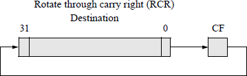
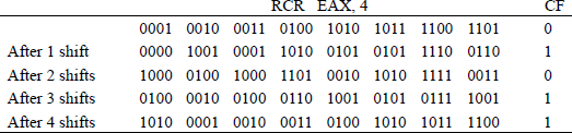
Figure 8.32 shows an assembly language module embedded in a C program that illustrates the application of the ROR instruction and the RCR instruction using the general-purpose register EAX as the destination operand. An 8-digit hexadecimal number is entered from the keyboard and displayed together with the resulting destination operand. The clear carry flag (CLC) resets the carry flag in the EFLAGS register to a value of 0 prior to execution of the RCR instruction.
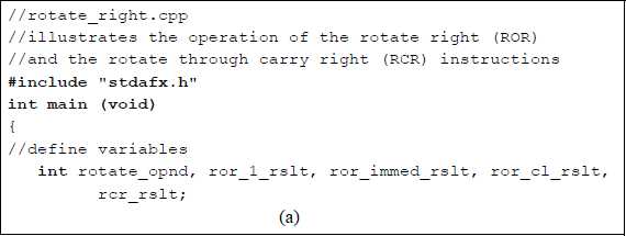
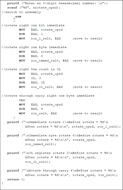
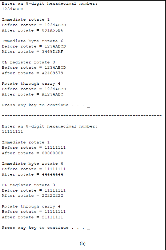
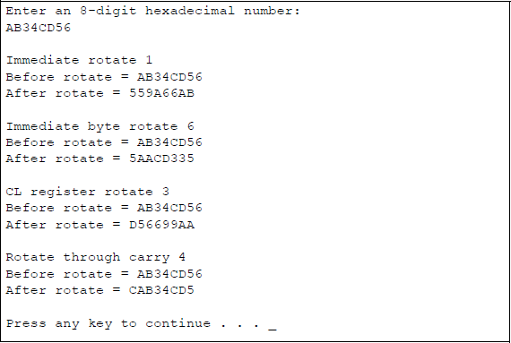
Program to illustrate the application of the ROR and the RCR instructions: (a) the program and (b) the outputs.
8.11 Problems
8.1 For each of the sections shown below, where the values are in hexadecimal, obtain the resulting values for register AX and the flags. Then write an assembly language module that is embedded in a C program to verify the results and print the results and the flags. When inserting hexadecimal numbers in an assembly language program manually, the first digit must be a number 0 through 9, then the digits A through F, if required, followed by the hexadecimal radix specifier H.
(a)
(b)
(c)
8.2 Use an XOR instruction to do the following:
(a) Exclusive-OR the memory operand addressed by register BX with the contents of register DX. Save the result in the memory location addressed by BX.
(b) Change the contents of register CL from 53H to 73H.
8.3 Using only logic instructions, write one instruction for each of the following parts that will perform the indicated operations.
(a) Set the low-order four bits of register AX.
(b) Reset the high-order three bits of register AX.
(c) Invert bits 7, 8, and 9 of register AX.
8.4 Write an assembly language program — not embedded in a C program — to perform an AND operation of two single hexadecimal characters that are entered from the keyboard. There is no space between the characters. Display the result of the AND operation and the low-order four bits of the flags register.
8.5 Assume that register AL contains an ASCII code for an uppercase letter. Write a single instruction to change the contents to the corresponding lowercase letter.
8.6 Determine the contents of registers AX, AH, and BL after the following program segment has been executed:
MOV CL, 3MOV AX, 7FHMOV BX, 0505HROL AX, CLAND AH, BHOR BL, AL8.7 Write an assembly language module embedded in a C program that executes the bit test instructions BTS, BTR, and BTC. Enter a 4-digit hexadecimal number for the operand and a 2-digit hexadecimal number for the bit offset. Store the operand in register AX. The program consists of two segments: one segment for an immediate bit offset and one segment for an offset in register BX. Include bit offsets greater than 16 so that the bit offset modulo-16 will generate a bit position in register AX. Display the results of the BTS, BTR, and BTC instructions for both the immediate bit offsets and the bit offset in register BX.
8.8 Write an assembly language module embedded in a C program that uses the bit scan forward (BSF) instruction to detect whether the first bit detected is in the low-order half or the high-order half of a 32-bit operand. Do not determine the bit position.
8.9 Repeat problem 8.8 using the bit scan reverse (BSR) instruction.
8.10 Determine the contents of register AX after execution of the following program segment:
MOV AX, –15MOV CL, 3SAL AX, CL8.11 Determine the contents of register AX after execution of the following program segment:
MOV AX, –32,668MOV CL, 5SAR AX, CL8.12 Determine the contents of register EBX and the flags register after execution of the program segment shown below. Then write an assembly language module embedded in a C program to verify the results.
MOV EBX, 0FFFFA85BHSAL EBX, 20MOV EBX, 0FFFFA85BHSAR EBX, 208.13 Determine the contents of the destination register EBX, the source register EDX, and the flags register after execution of the program segment shown below and on the following page. Then write an assembly language module embedded in a C program to verify the results.
MOV EBX, 1234ABCDHMOV EDX, 0ABCD1234HMOV CL, 16SHLD EBX, EDX, CL
MOV EBX, 1234ABCDHMOV EDX, 0ABCD1234HMOV CL, 16SHRD EBX, EDX, CL8.14 Write an assembly language module embedded in a C program that will multiply and divide a decimal number by 8 using arithmetic shift instructions. When dividing, some numbers will have the fraction truncated.
8.15 Write an assembly language program — not embedded in a C program — that requests one of three 1-digit numbers (1, 2, or 3) to be entered from the keyboard. Determine which number was entered, then display the number. Use the AND instruction to remove the ASCII bias.
8.16 Let register EAX contain AD3E14B5H and the carry flag be set. Determine the contents of register EAX after the following instruction is executed:
RCL EAX, 68.17 Let register EAX contain 12345678H and the carry flag be set. Determine the contents of register EAX after the following instruction is executed:
RCR EAX, 68.18 Let register EAX contain 1C78FDA5 and the carry flag be set. Determine the contents of register EAX after the following instruction is executed:
RCR EAX, 68.19 Write an assembly language module embedded in a C program that illustrates the shift logical left (SHL), shift logical right (SHR), rotate left (ROL), and rotate right (ROR) instructions. Enter an 8-digit hexadecimal number for the destination operand with a count of 40 stored in register CL.
8.20 This problem is similar to Problem 8.15. Write an assembly language module embedded in a C program that requests one of three 1-digit numbers (3, 4, or 5) to be entered from the keyboard. Determine which number was entered, then display the number. If an incorrect number is entered, then display that information.