Table of Contents for
X86 Assembly Language and C Fundamentals
 X86 Assembly Language and C Fundamentals
Published by
CRC Press, 2015
X86 Assembly Language and C Fundamentals
Published by
CRC Press, 2015
- X86 Assembly Language and C Fundamentals
- Preliminaries
- By the same Author
- X86 Assembly Language and C Fundamentals
- X86 Assembly Language and C Fundamentals
- Preface
- Chapter 1 Number Systems and Number Representations
- Chapter 2 X86 Processor Architecture
- Chapter 3 Addressing Modes
- Chapter 4 C Programming Fundamentals
- Chapter 5 Data Transfer Instructions
- Chapter 6 Branching and Looping Instructions
- Chapter 7 Stack Operations
- Chapter 8 Logical, Bit, Shift, and Rotate Instructions
- Chapter 9 Fixed-Point Arithmetic Instructions
- Chapter 10 Binary-Coded Decimal Arithmetic Instructions
- Chapter 11 Floating-Point Arithmetic Instructions
- Chapter 12 Procedures
- Chapter 13 String Instructions
- Chapter 14 Arrays
- Chapter 15 Macros
- Chapter 16 Interrupts and Input/Output Operations
- Chapter 17 Additional Programming Examples
- Appendix A ASCII Character Codes
- Appendix B Answers to Select Problems
Chapter 9
Fixed-Point Arithmetic Instructions
In fixed-point operations, the radix point is in a fixed location in the operand. The radix point (or binary point for radix 2) is to the immediate right of the low-order bit for integers, or to the immediate left of the high-order bit for fractions. The operands in a computer can be expressed by any of the following number representations: unsigned, sign-magnitude, diminished-radix complement, or radix complement.
If the numbers are signed, then the sign bit can be extended to the left indefinitely without changing the value of the number. An n-bit signed number A is shown in Equation 9.1, where the leftmost digit an_1 is the sign bit. The sign bit for any radix is 0 for positive numbers and r -1 for negative numbers, as shown in Equation 9.2.
9.1 Addition
Addition of two binary operands treats both signed and unsigned operands the same — there is no distinction between the two types of numbers during the add operation. The operands for addition are the augend and the addend, where the addend is added to the augend and the sum replaces the augend in most computers — the addend is unchanged. The rules for radix 2 addition are shown in Table 9.1.
(1) 1 + 1 = 0 with a carry to the next higher-order column.
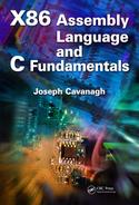
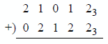
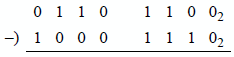
An example of binary addition is shown in Figure 9.1. The subscripted values are the carries from the previous columns. For example, in column 1 the sum of five 1s is 510 (1012). Therefore, there is a carry of 0 to column 2 and a carry of 1 to column 3. The sum of column 2 is 310 (112), which yields a sum of 1 with a carry of 1 to column 3. In column 3, the sum is 610 (1102), which yields a sum of 0 with a carry of 1 to column 4 and a carry of 1 to column 5. The total sum is 5110 (1100112).
Now consider the rightmost four columns and assume that the operands are in 2s complement representation. Operand 1 is negative because the sign is 1 ; therefore, the value is -5 (the 0 in column 3 has a value of 4 + 1 = 5). Using the same rationale. operand 2 is also negative with a value of -3. Operand 3 is positive because the sign is 0; therefore, the value is +5. Operand 5 is negative with a value of -1 (count the zeroes by their weight and add one).
9.1.1 Add (ADD) Instruction
The add (ADD) instruction obtains the sum of the destination operand (the augend) and the source operand (the addend) and stores the result in the destination operand. The destination operand (first operand) can be a general-purpose register or a memory location. The source operand (second operand) can be a general-purpose register, a memory location, or a signed immediate operand with the sign extended to match the size of the destination operand, if necessary. The syntax for the ADD instruction is shown below.
ADD register/memory, register/memory/immediate
The ADD instruction operates on integer operands only and affects the following flags: the overflow flag (OF), the sign flag (SF), the zero flag (ZF), the auxiliary carry flag (AF), the parity flag (PF), and the carry flag (CF).
Overflow occurs when the result of an arithmetic operation (usually addition) exceeds the word size of the machine; that is, the sum is not within the representable range of numbers provided by the number representation. For numbers in 2s complement representation, the range is from -2n-1 to + 2n-1 - 1. For two n-bit numbers
and are the sign bits of operands A and B, respectively. Overflow can be detected by either of the following two equations:
where the symbol "•" is the logical AND operator, the symbol "+" is the logical OR operator, the symbol "⊕" is the logical exclusive-OR operator, the sign bit of the result is , and the carry bits out of positions n - 1 and n - 2 are and , respectively.
Thus, overflow produces an erroneous sign reversal and is possible only when both operands have the same sign. An overflow cannot occur when adding two operands of different signs, since adding a positive number to a negative number produces a result that falls within the limit specified by the two numbers. Two examples of overflow are shown below: one for positive numbers and one for negative numbers, where both operands are in 2s complement representation.
For the first example, the sum of +161 requires nine bits: 0 1010 0001; therefore, an overflow has occurred. For the second example, the sum of-131 also requires nine bits: 1 0111 1101; therefore, an overflow has occurred.
The sign flag (SF) is set to the value of the high-order bit of the result; the zero flag (ZF) is set if the sum is zero; the auxiliary carry flag (AF) is set if there is a carry from column 23 to column 24 , which occurs in the first example; the parity flag (PF) is set if there are an even number of 1s in the result (low-order byte only); and the carry flag (CF) is set if there is a carry out of the high-order bit positions.
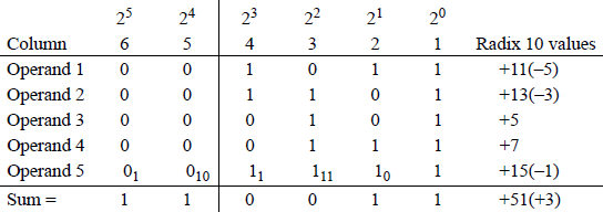
Figure 9.2 shows an assembly language module embedded in a C program that illustrates an ADD instruction in which all of the flags in the low-order byte of the EFLAGS register are set for specific augends and addends.
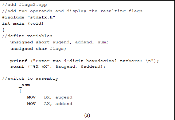
Program to illustrate the AND instruction and flag generation: (a) the program and (b) the outputs.
9.1.2 Add with Carry (ADC) Instruction
The add with carry (ADC) instruction adds two integers plus the carry flag (CF = 0 or 1). It is typically used when adding two signed or unsigned operands, which can be multiple bytes, words, doublewords, or larger operands — the carry is propagated from one stage to the next stage. The ADC instruction adds the destination operand, the source operand, and the carry flag and stores the sum in the destination operand. The syntax for the ADC instruction is shown below; however, both operands cannot be in memory.
ADC register/memory, register/memory/immediate
The value of the carry flag represents a carry from a previous addition of two operands in a multioperand addition. An immediate operand is sign extended to match the size of the destination operand, if necessary. The ADC instruction normally follows an ADD instruction of a multioperand addition. If a REX prefix is used in 64-bit mode, the number of general-purpose registers is increased from eight to sixteen and can be extended to 64 bits.
Figure 9.3 shows a program segment that depicts the ADC instruction to add two 32-bit operands in two sections. First the low-order section is added, then the high-order section is added plus any carry generated from the addition of the low-order section. The operands are shown below in two segments. Figure 9.4 shows how the numbers are stored in memory.
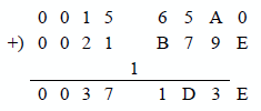
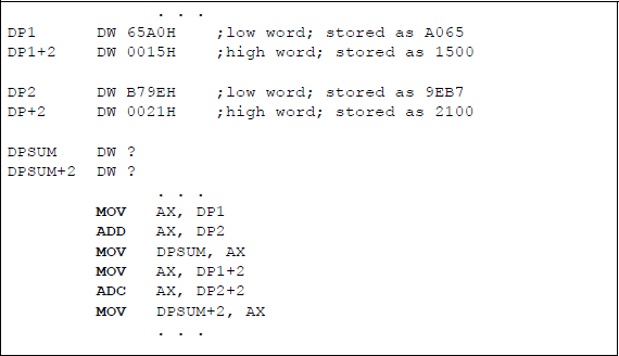
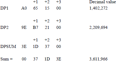
Figure 9.5 lists an assembly language module embedded in a C program that adds the numbers given in this section. The program adds the two 32-bit operands in two sections: first the low-order segment, then the high-order segment plus the carry from the low-order segment. Both operands are entered as immediate data and the sum is declared as sum1 and sum2 for the low-order and the high-order segments, respectively.
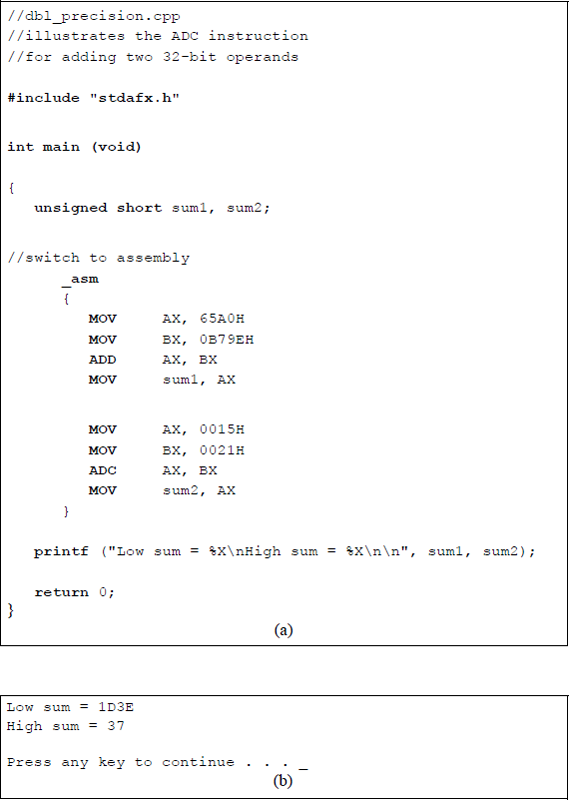
Program illustrating using the ADC instruction to add two 32-bit operands: (a) the program and (b) the outputs.
Figure 9.6 depicts a program segment illustrating a numerical example of adding two operands: a 32-bit augend and a 16-bit addend using the add with carry (ADC) instruction in conjunction with the convert word to doubleword (CWD) instruction.
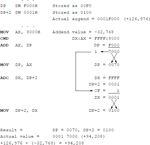
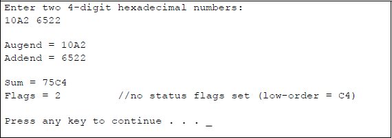
Figure 9.7 shows an assembly language module embedded in a C program that adds two unequal length operands using the ADC instruction in combination with the CWD instruction, this time using hexadecimal numbers that are entered from the keyboard. The augend consists of 32 bits, whereas the addend consists of 16 bits. The first operands are those shown in Figure 9.6.
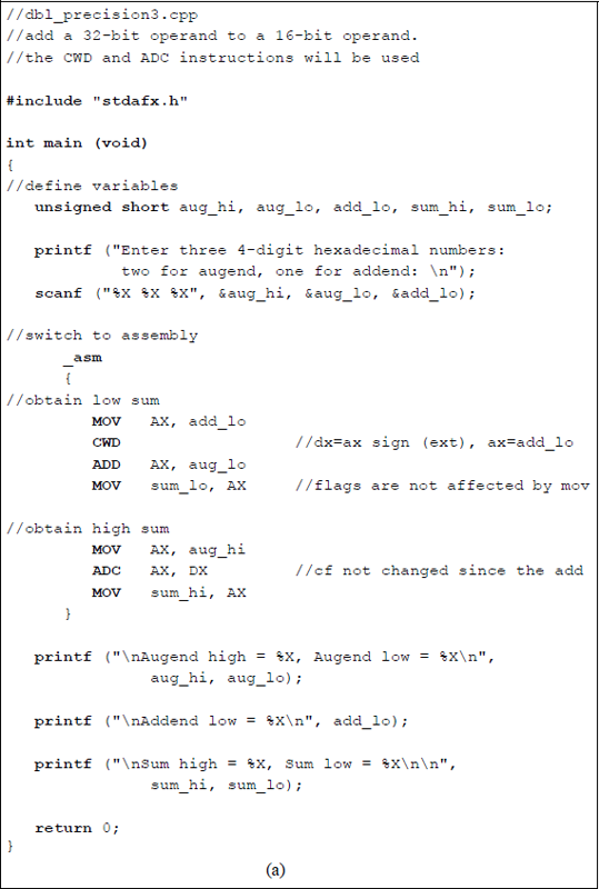
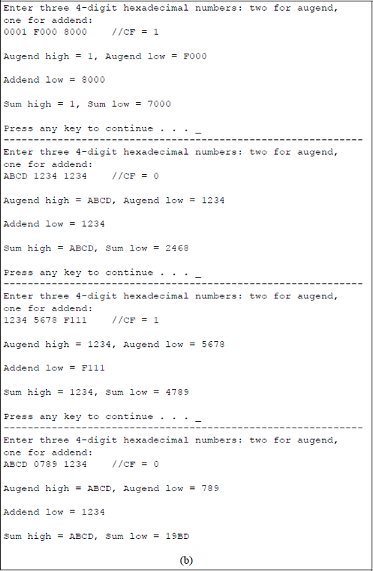
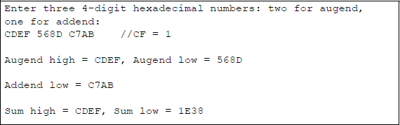
Using the ADC instruction in conjunction with the CWD instruction to add a 32-bit augend to a 16-bit addend: (a) the program and (b) the outputs.
The CWD instruction effectively doubles the size of the operand in the implied general-purpose register AX by extending the sign in AX throughout register DX. Thus, the result obtained by executing the CWD instruction is stored in register pair DX: AX, where the colon signifies concatenation. The 32-bit contents of the addend in registers DX:AX can now be added to the 32-bit augend. No flags are affected by the CWD instruction.
9.1.3 Increment by 1 (INC) Instruction
The increment by 1 (INC) instruction is used primarily to increment counters and other unsigned integers by a value of 1. The INC instruction adds 1 to the destination operand, but does not affect the carry flag (CF). The flags that are affected are the overflow flag (OF), the sign flag (SF), the zero flag (ZF), the auxiliary flag (AF), and the parity flag (PF). The destination operand can be a value in a general-purpose register or a value in a memory location. The syntax for the INC instruction is shown below.
INC register/memory
Binary-to-Gray code conversion A sufficient number of instructions have now been presented in order to illustrate the binary-to-Gray code conversion algorithm. A procedure for converting from the binary 8421 code to the Gray code can be formulated. Let an n-bit binary code word be represented as
and an n-bit Gray code word be represented as
where and are the low-order bits of the binary and Gray codes, respectively. The ith Gray code bit can be obtained from the corresponding binary code word by the following algorithm:
for 0 ≤ i ≤n − 2, where the symbol ⊕ denotes modulo-2 addition defined as:
Table 9.2 shows the relationship between the binary 8421 code and the Gray code. The Gray code belongs to a class of cyclic codes called reflective codes. Notice in the first four rows, that reflects across the reflecting axis; that is, in rows 2 and 3 is the mirror image of in rows 0 and 1 . In the same manner, and reflect across the reflecting axis drawn under row 3. Thus, rows 4 through 7 reflect the state of rows 0 through 3 for and . The same is true for , , and relative to rows 8 through 15 and rows 0 through 7. The Gray code is an unweighted code where only one input changes between adjacent code words.
Table for Converting from the Binary 8421 Code to the Gray code
Binary code |
Gray code |
||||||||
|---|---|---|---|---|---|---|---|---|---|
Row |
b3 |
b2 |
b1 |
b0 |
g3 |
g2 |
g1 |
g0 |
|
0 |
0 |
0 |
0 |
0 |
0 |
0 |
0 |
0 |
|
1 |
0 |
0 |
0 |
1 |
0 |
0 |
0 |
1 |
|
2 |
0 |
0 |
1 |
0 |
0 |
0 |
1 |
1 |
← g0 is reflected |
3 |
0 |
0 |
1 |
1 |
0 |
0 |
1 |
0 |
|
4 |
0 |
1 |
0 |
0 |
0 |
1 |
1 |
0 |
← g1 and g0 |
5 |
0 |
1 |
0 |
1 |
0 |
1 |
1 |
1 |
are reflected |
6 |
0 |
1 |
1 |
0 |
0 |
1 |
0 |
1 |
|
7 |
0 |
1 |
1 |
1 |
0 |
1 |
0 |
0 |
|
8 |
1 |
0 |
0 |
0 |
1 |
1 |
0 |
0 |
← g2, g1, and g0 |
9 |
1 |
0 |
0 |
1 |
1 |
1 |
0 |
1 |
are reflected |
10 |
1 |
0 |
1 |
0 |
1 |
1 |
1 |
1 |
|
11 |
1 |
0 |
1 |
1 |
1 |
1 |
1 |
0 |
|
12 |
1 |
1 |
0 |
0 |
1 |
0 |
1 |
0 |
|
13 |
1 |
1 |
0 |
1 |
1 |
0 |
1 |
1 |
|
14 |
1 |
1 |
1 |
0 |
1 |
0 |
0 |
1 |
|
15 |
1 |
1 |
1 |
1 |
1 |
0 |
0 |
0 |
|
Equation 9.4 indicates that the conversion process can be achieved by repetitive use of the exclusive-OR function. For example, using the algorithm of Equation 9.4, the 4-bit binary code word translates to the 4-bit Gray code word as follows:
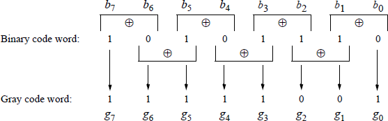
An example is shown in Figure 9.8 using the algorithm of Equation 9.4 to translate an 8-bit binary code word to an 8-bit Gray code word as follows:
An assembly language program will now be written to convert a binary code to the corresponding Gray code. Recall that a parameter list (PARLST) is used in the data segment (DTSG) to contain the maximum length (MAXLEN) of the operand field (OPFLD) and the actual length (ACTLEN) of the operand field after data have been entered from the keyboard.
A diagram of the parameter list in the data segment is shown in Figure 9.9 that contains an example of eight binary bits (10101110) that have been entered from the keyboard to be converted to the Gray code. The 1 and 0 bits are entered as ASCII characters and stored in the operand field — numbers have an ASCII bias of 3 (0011). The resulting Gray code is stored in the result area (RSLT) of the data segment and must also be represented as ASCII characters in order to be displayed correctly.
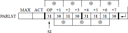
Figure 9.10 contains an assembly language program — not embedded in a C program — that converts binary data to the Gray code. The comments in the code describe the program execution. When performing the exclusive-OR on two ASCII numbers, there is no need to remove the ASCII bias of 3 (0011). For example, 1 ⊕ 1 = 0; that is, 31H ⊕ 31H = 00110001 ⊕ 00110001 = 00000000, which is correct. Before the Gray code number can be displayed, however, the ASCII bias must be restored by performing either the OR operation or the ADD operation of 3OH with the resulting Gray code bit. The same reasoning is true for 1 ⊕ 0.
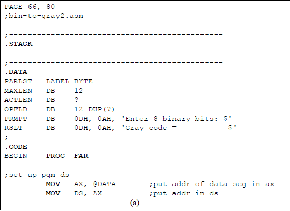
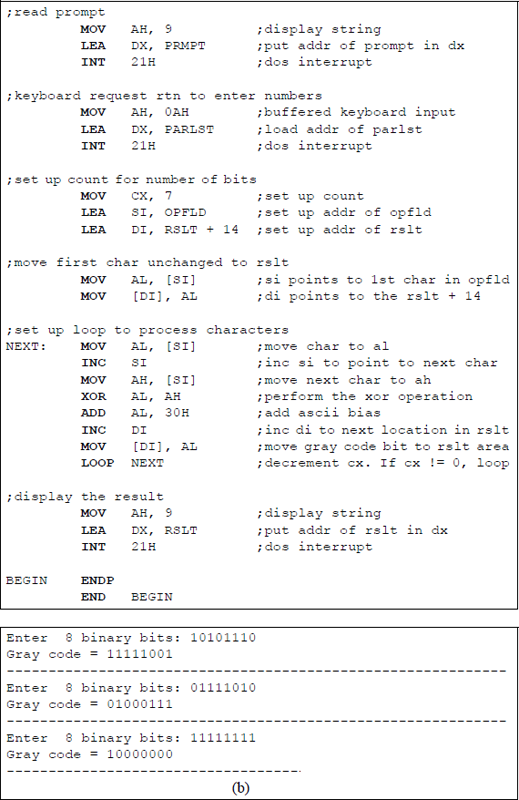

Program to convert binary data to the corresponding Gray code: (a) the program and (b) the outputs.
9.2 Subtraction
The two operands for subtraction are the minuend and the subtrahend — the subtrahend is subtracted from the minuend according to the rules shown in Table 9.3 for radix 2.
Truth Table for Subtraction
0−0 |
= |
0 |
|
0−1 |
= |
1 |
with a borrow from the next higher-order minuend |
1−0 |
= |
1 |
|
1−1 |
= |
0 |
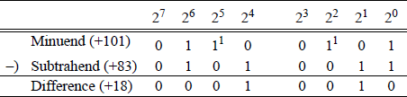
An example is shown in Figure 9.11 using the rules of Table 9.3, in which the subtrahend 0101 0011 (+83) is subtracted from the minuend 0110 0101 (+101), resulting in a difference of 0001 0010 (+18). This is called the paper-and-pencil method, but is not applicable for subtraction in a computer. The difference in column 21 is 0 - 1 = 1 with a borrow from the minuend in column 22 , which results in a difference of 0 - 0 = 0 in column 22. The same rationale applies to column 24 and column 25 .
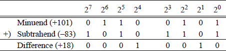
Subtraction is similar to addition, because computers use an adder for the subtraction operation by adding the radix complement of the subtrahend to the minuend. Recall that the rs complement is obtained from the r - 1 complement by adding 1. For radix 2, the 2s complement is obtained by adding 1 to the 1s complement. Arithmetic processors use an adder to perform subtraction by adding the 2s complement of the subtrahend to the minuend. Let A and B be two n-bit operands, where A is the minuend and B is the subtrahend as follows:
Therefore, , where B′ is the 1s complement of B. Figure 9.11 is repeated as shown in Figure 9.12 using this method.
When subtracting two operands by adding the 2s complement of the subtrahend, the states of the auxiliary carry flag (AF) and the carry flag (CF) are inverted. For example, a subtraction will be performed on the following operands: minuend 0110 0001 (+97) and subtrahend 0110 0101 (+101) to yield a difference of 1111 1100 (-4). Figure 9.13(a) shows the paper-and-pencil method — including borrows — and Figure 9.13(b) shows the same subtraction accomplished by adding the 2s complement of the subtrahend — including carries.
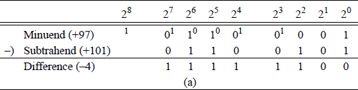
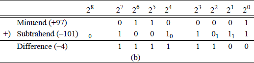
Two methods of subtraction: (a) the paper-and-pencil method and (b) adding the 2s complement of the subtrahend.
In Figure 9.13(a), the borrow from column 24 represents the auxiliary carry flag (AF =1) and the borrow from column 28 represents the carry flag (CF =1). Since column 24 has a 0 in the minuend, the borrow must come from column 25 , which leaves a 0 for the minuend in column 25 . The process repeats for columns 25 through column 28. In Figure 9.15(b), the auxiliary carry flag and the carry flag are indicated as having a value of 0; however, the true values are 1.
Additional examples of subtraction are shown in Figure 9.14 for both positive and negative operands using the radix complement (2s complement) method.
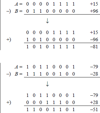
Additional examples of subtraction in which the radix complement of the subtrahend is added to the minuend.
This section presents the following subtract instructions: subtract (SUB), integer subtraction with borrow (SBB), decrement by 1 (DEC), and negate (NEG).
9.2.1 Subtract (SUB) Instruction
The subtract instruction performs a subtraction on signed (2s complement) or unsigned integer operands that can be bytes, words, or doublewords. The syntax for the subtract operation is shown below. The source operand (second operand — subtrahend) is subtracted from the destination operand (first operand — minuend) and stores the difference in the destination operand.
SUB register/memory, register/memory/immediate
The destination operand can be a register or a memory location; the source operand can be a register, a memory location, or an immediate value; however, both operands cannot be in memory. When an immediate operand is used, it is sign-extended to match the size of the destination operand, if necessary.
The following flags are affected: the overflow flag (OF), the sign flag (SF), the zero flag (ZF), the auxiliary carry flag (AF), the parity flag (PF), and the carry flag (CF). If signed operands are utilized, then the overflow flag is set to indicate an overflow condition. The default operand size is 32 bits in 64-bit mode. Using a REX prefix allows access to eight additional registers: R8 through R15.
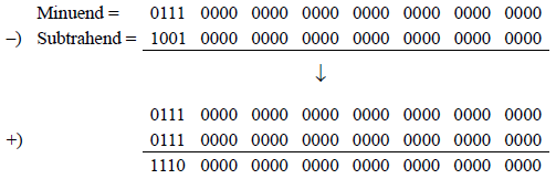
Figure 9.15 shows an assembly language module embedded in a C program that illustrates the use of the SUB instruction. Two signed or unsigned decimal operands are entered from the keyboard — the first is for the minuend, the second is for the subtrahend. After the subtraction takes place, the resulting difference and flags are displayed. The program is shown in Figure 9.15(a) and the outputs for various operands are shown in Figure 9.15(b).
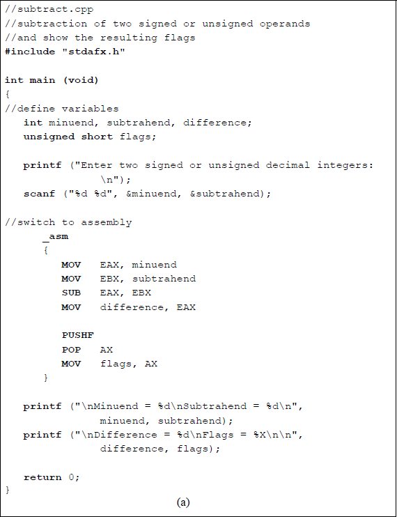
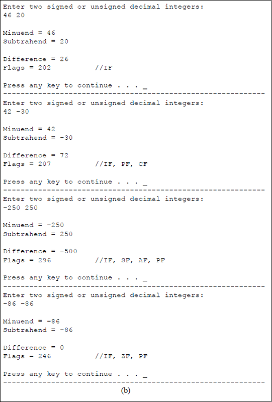
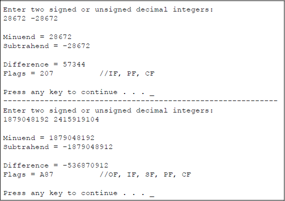
Program to illustrate the use of the SUB instruction: (a) the program and (b) the outputs.
The results of the first five pairs of operands are easy to understand. The fifth pair of operands has a minuend value of 187904819210 which is 0111 0000 0000 0000 0000 0000 0000 00002 and a subtrahend value of 241591910410 which is 1001 0000 0000 0000 0000 0000 0000 00002. When the subtrahend is negated it becomes 0111 0000 0000 0000 0000 0000 0000 00002, resulting in an overflow condition for a difference of 375809638410 which is 1110 0000 0000 0000 0000 0000 0000 00002 as shown below.
It can be clearly seen that an overflow has occurred, because the signs of the operands and result satisfy the following equation: . The sign flag has a value of 1; the parity flag has a value of 1, because the low-order byte has an even number of 1s; and the carry flag is 1, because 0-1 = 1 with a borrow from the next higher-order bit of the minuend (refer to Table 9.3).
9.2.2 Integer Subtraction with Borrow (SBB) Instruction
The SBB instruction subtracts the source operand (second operand) from the destination operand (first operand) and subtracts 1 if the carry flag is set — the carry flag represents a borrow from a previous subtraction. This operation is accomplished by adding the source operand and the carry flag, then subtracting the sum from the destination operand. The difference is stored in the destination operand.
The SBB instruction is used to subtract multiple bytes or words and is preceded by a SUB instruction. The destination operand can be a register or a memory location; the source operand can be a register, an immediate operand, or a memory location. However, both operands cannot be memory locations. The syntax for the SBB instruction is shown below.
SBB register/memory, register/immediate/memory
If an immediate operand is used, the sign is extended to match the size of the destination operand. The SBB instruction is used for both signed and unsigned operands. The overflow flag (OF) is used in conjunction with signed operands; the carry flag (CF) is used for unsigned operands. Using an REX prefix allows access to eight supplementary registers: R8 through R15.
The affected flags resulting from the SBB instruction are the overflow flag (OF), the sign flag (SF), the zero flag (ZF), the auxiliary carry flag (AF), the parity flag (PF), and the carry flag (CF).
9.2.3 Decrement by 1 (DEC) Instruction
The DEC instruction subtracts 1 from the destination operand, which is an integer operand. The destination operand can be a register or a memory location. The affected flags resulting from the DEC instruction are the overflow flag (OF), the sign flag (SF), the zero flag (ZF), the auxiliary carry flag (AF), and the parity flag (PF); the carry flag (CF) is not affected. If the state of the carry flag is required, then a subtraction with an immediate value of 1 can be executed. The DEC instruction can also access eight additional registers — R8 through R15 — if an REX prefix is utilized. The syntax for the DEC instruction is shown below.
DEC register/memory
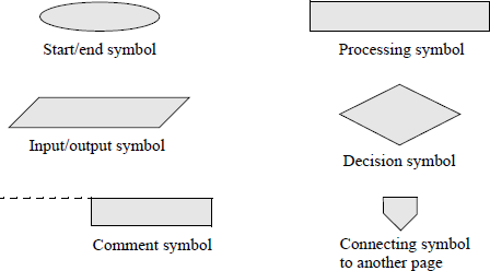
An assembly language program — not embedded in a C program — will now be presented that obtains the sum of the smallest and largest n single-digit numbers that are entered from the keyboard, where n can range from 1 to a much larger number, for example 30. The DEC instruction will be used throughout the program. Any program of this size is easier to implement if a flowchart is developed prior to coding the program. There are six main symbols used in drawing flowcharts, as shown in Figure 9.16. Arrows indicate the control flow through the flowchart.
The flowchart for this program is shown in Figure 9.17. The program will be designed directly from the flowchart. The stack, data, and code segments are initialized in the processing symbol following the start symbol. The initialize symbol sets up the program's data segment (DS). Numbers are entered using the parallelogram labelled keyboard rtn. The decision symbol labelled 1 digit entered? checks to determine if only one number was entered. The remaining symbols are self-explanatory. The assembly language program is shown in Figure 9.18 and follows the sequence presented in the flowchart.
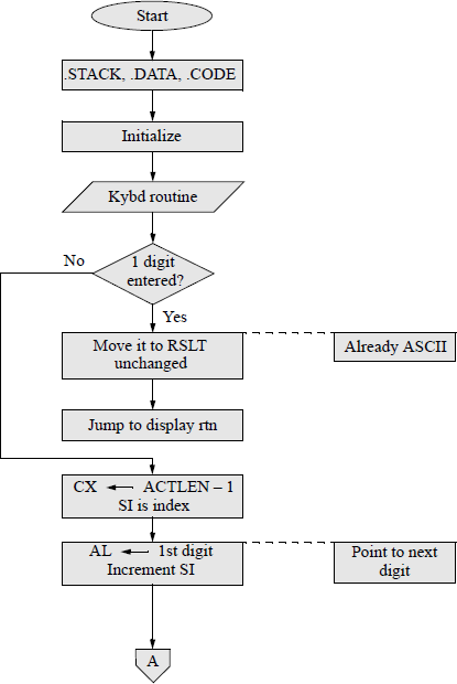
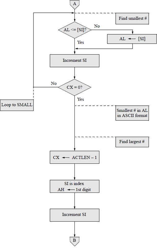
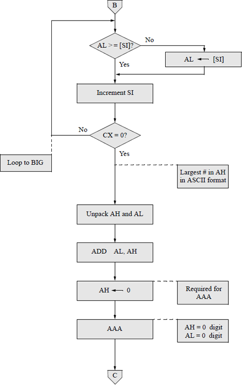
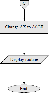
Flowchart for the assembly language program to obtain the sum of the smallest and largest single-digit numbers that are entered from the keyboard.
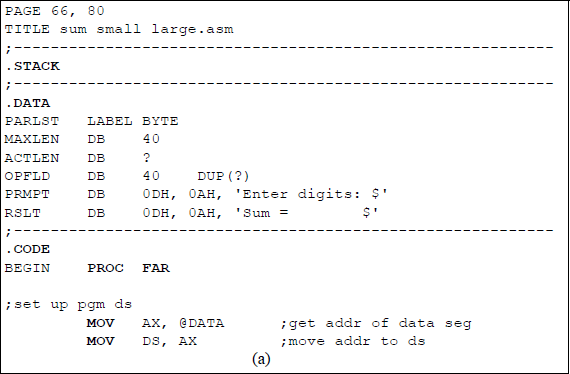
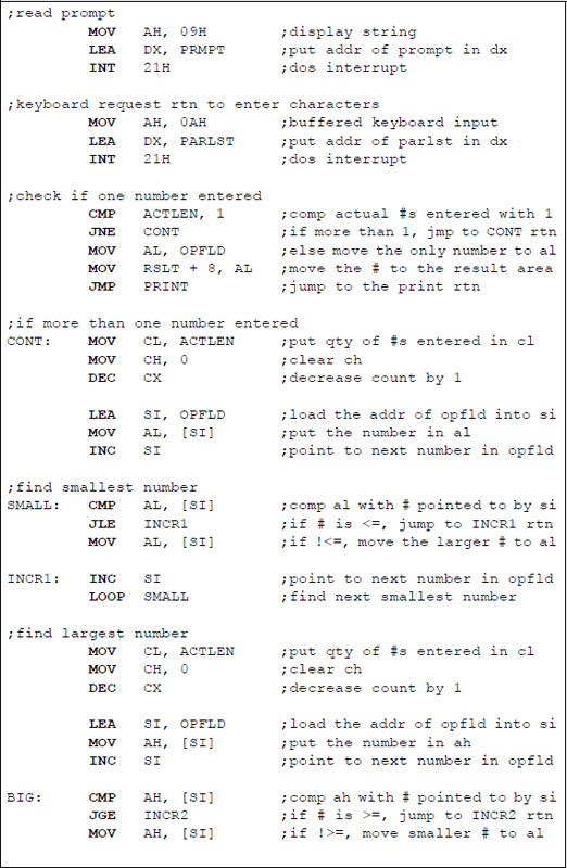
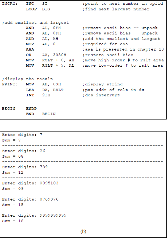
Assembly language program to obtain the sum of the smallest and largest single-digit numbers that are entered from the keyboard: (a) the program and (b) the outputs.
9.2.4 Two's Complement Negation (NEG) Instruction
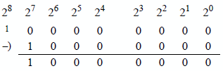
The NEG instruction generates the 2s complement of a number by subtracting the destination integer operand from zero. This procedure changes the sign of the number, but does not alter the absolute value of the number. Numbers that contain a high-order one preceded by all zeroes does not change when it is negated. For example, the number 1000 0000 (-128) will be negated by subtracting the number from zero, as shown below, using the rules of Table 9.3. The 1 bit in column 28 represents a borrow from column 28.
The destination operand can be in a register or a memory location. If an REX prefix is used in 64-bit mode, the number of general-purpose registers is increased from eight to sixteen and can be extended to 64 bits. The syntax for the NEG instruction is shown below.
NEG register/memory
If the destination operand is zero before the NEG instruction is executed, then the carry flag (CF) is reset to zero; otherwise, it is set to one. The remaining flags — OF, SF, ZF, AF, and PF — are set or reset depending on the result of the NEG instruction.
The negation of a number can also be accomplished using a paper-and-pencil method by keeping the low-order 0 bits and the first 1 bit unchanged, then inverting all remaining higher-order bits, as the number is scanned from right to left.
9.3 Multiplication
Fixed-point multiplication is more complex than either addition or subtraction. This section will present techniques and examples to multiply both signed and unsigned operands. The n-bit multiplicand A is multiplied by the n-bit multiplier B to produce a 2n-bit product P, as shown below.
An algorithm for the paper-and-pencil method will be described for multiplying unsigned and signed operands, then examples using these methods will be presented. The algorithm consists of multiplying the multiplicand by the low-order multiplier bit to obtain a partial product. If the multiplier bit is 1, then the multiplicand becomes the partial product; if the multiplier bit is 0, then zeroes become the partial product. For signed multiplication, the sign bit extends left to produce a partial product of 2n bits.
The partial product is then shifted left 1 bit position and the multiplicand is multiplied by the next higher-order multiplier bit to obtain a second partial product. Each partial product is shifted left relative to the previous partial product. The process repeats for all remaining multiplier bits, at which time the partial products are added to obtain the product.
For signed multiplication, the sign of the product is positive if both operands have the same sign. If the signs of the operands are different, then the sign of the product is negative. Multiplication of two fixed-point binary numbers is a process of repeated add-shift operations. There are two X86 assembly language instructions that are used for multiplication: unsigned multiply (MUL) and signed multiply (IMUL).
9.3.1 Unsigned Multiply (MUL) Instruction
The MUL instruction performs a multiplication on two unsigned integer operands: an unsigned multiplicand (destination operand) and an unsigned multiplier (source operand). The implied destination operand is in the accumulator — registers AL, AX, EAX, or RAX, which are a function of the size of the operands. The multiplier source operand can be in a general-purpose register or in a memory location.
The 2n-bit product is stored in register AX, register pair DX:AX, register pair EDX:EAX, or register pair RDX:RAX. The high-order bits of the product are in registers AH, DX, EDX, or RDX. If the high-order bits of the product are not all zeroes, then the carry flag (CF) and the overflow flag (OF) are set. The syntax is as follows:
MUL register/memory
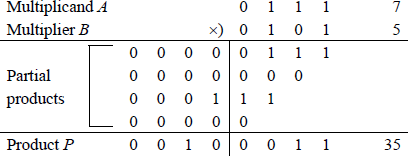
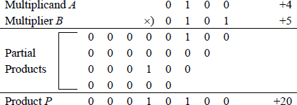
Example 9.1 This example multiplies two 4-bit operands, both with 0s as the high-order bits: multiplicand a[3:0] = 0111 (7) and multiplier b[3:0] = 0101 (5) to produce a product p[7:0] = 0010 0011 (35). A multiplier bit of 1 copies the multiplicand to the low-order four bits of the partial product with zeroes extended to eight bits; a multiplier bit of 0 enters zeroes in the partial product.
Example 9.2 This example multiplies two 4-bit operands, both with 1 s as the high-order bits: multiplicand a[3:0] = 0111 (7) and multiplier b[3:0] = 0101 (5) to produce a product p[7:0] = 0010 0011 (35). A multiplier bit of 1 copies the multiplicand to the low-order four bits of the partial product with zeroes extended to eight bits; a multiplier bit of 0 enters zeroes in the partial product.
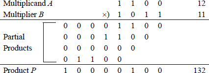
Figure 9.19 shows a listing for an assembly language module embedded in a C program that multiplies an unsigned multiplicand in register EAX by an unsigned multiplier. The flags are displayed after the multiply operation has been executed. The first set of operands that are entered from the keyboard result in the high-order part of the product being equal to zero; thus, the overflow flag and the carry flag are reset.
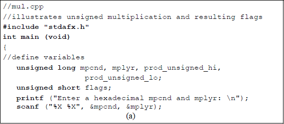
Program to illustrate unsigned multiplication and the resulting flags: (a) the program and (b) the outputs.
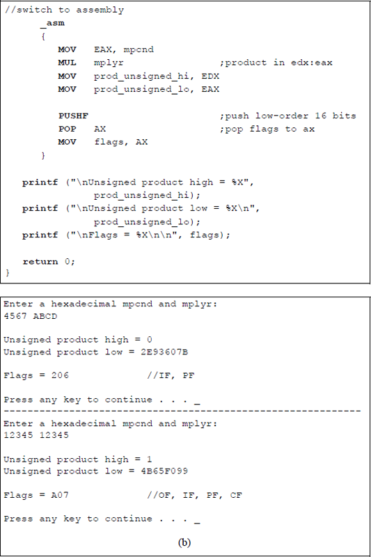
The second set of operands result in the high-order part of the product being nonzero; thus, the overflow flag and the carry flag are set. In both cases the parity flag is set, because the low-order byte contains an even number of ones. Although the operands are normally the same length, it is also possible to multiply operands of different lengths, as shown in Figure 9.20 for a doubleword multiplicand and a word multiplier. When the MUL instruction is used to multiply two unsigned operands, the operands are treated as unsigned even though the high-order bit — normally the sign bit — is a 1.
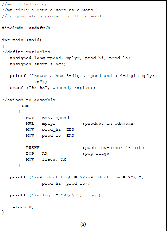
Program to illustrate multiplying a doubleword multiplicand by a word multiplier: (a) the program and (b) the outputs.
9.3.2 Signed Multiply (IMUL) Instruction
The IMUL instruction executes a multiply operation on a signed multiplicand and a signed multiplier. There are three forms for the IMUL instruction, which are a function of the operands being used: one operand, two operands, or three operands. When the IMUL instruction is used to multiply two signed operands, the high-order bit represents the sign bit — 0 for positive operands and 1 for negative operands. For both the MUL instruction and the IMUL instruction, an REX prefix in 64-bit mode increases the number of general-purpose registers from eight to sixteen and can be extended to 64 bits.
One operand This form is equivalent to the syntax used for the MUL instruction; thus, the source operand is in a general-purpose register or in a memory location. The implied destination operand is in the accumulator — registers AL, AX, EAX, or RAX, which are a function of the operand size. The syntax for the one operand IMUL instruction is shown below.
IMUL register/memory
Two operands This form multiplies the destination operand (first operand) by the source operand (second operand) and stores the product in the destination operand. The destination operand is a general-purpose register and the source operand is a general-purpose register, a memory location, or an immediate operand. The syntax for the two-operand IMUL instruction is shown below.
IMUL register, register/memory/immediate
Three operands This form uses three operands: the destination operand (first operand) and two source operands (second operand and third operand). The destination operand is a general-purpose register; the first source operand can be a general-purpose register or a memory location; the second source operand is an immediate value. The first source operand is multiplied by the second source operand and the product is stored in the destination operand. If an immediate operand is utilized, the sign extends to match the size of the destination operand.
If the high-order half of the product is not the sign extension, then the overflow flag (OF) and the carry flag (CF) are set; otherwise, the flags are reset. When the overflow flag and the carry flag are set, this indicates that the high-order half of the product contains significant bits of the result. The sign flag (SF), the zero flag (ZF), the auxiliary carry flag (AF), and the parity flag (PF) are undefined following execution of the IMUL instruction. An n-bit multiplicand and an n-bit multiplier produce a 2n-bit product. The syntax for the three-operand IMUL instruction is shown below.
IMUL register, register/memory, immediate
An algorithm for the paper-and-pencil method will be described for multiplying signed operands, then examples using this method will be presented. The algorithm is similar to that used for unsigned operands and consists of multiplying the multiplicand by the low-order multiplier bit to obtain a partial product. If the multiplier bit is a 1, then the multiplicand becomes the partial product with the sign extended to match the size of the 2n-bit product; if the multiplier bit is a 0, then zeroes become the partial product with zeroes extended to match the size of the 2n-bit product.
The partial product is then shifted left 1 bit position and the multiplicand is multiplied by the next higher-order multiplier bit to obtain a second partial product. Each partial product is shifted left relative to the previous partial product. The process repeats for all remaining multiplier bits, at which time the partial products are added to obtain the product. The sign of the product is positive if both operands have the same sign; the sign of the product is negative if the signs of the operands are different.
Example 9.3 This example multiplies a 4-bit negative multiplicand by a 4-bit negative multiplier to yield an 8-bit positive product. In the paper-and-pencil method, both operands must be positive to obtain the correct positive product. This can be easily accomplished by 2s complementing both operands. If the operands were not negated, then the result would be incorrect due to sign extension in order to generate the partial products. This is not a problem when using the IMUL instruction — the operands do not have to be negated. In this example, the multiplicand is , the multiplier is , to generate a product when both operands are negated.
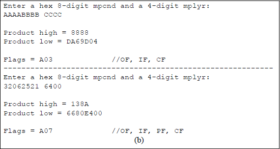
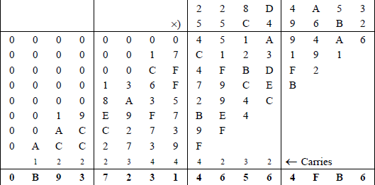
Example 9.4 This example performs a signed multiplication on two doubleword positive operands: a multiplicand with a hexadecimal value of 228D4A53 and a multiplier with a hexadecimal value of 55C496B2. The multiplication will be performed first using the paper-and-pencil method to display all of the partial products, as shown in Figure 9.21. Then the product will be verified using an assembly language module embedded in a C program in which the operands are entered from the keyboard. The one-operand IMUL form will be used. The three-operand form is assigned as a problem.
The program will also multiply two additional pairs of operands that are entered from the keyboard: a positive multiplicand and a negative multiplier; and a negative multiplicand and a positive multiplier of the same absolute value as the previous values. The product will be the same in both cases. Figure 9.22 illustrates the program for the doubleword multiplication using an assembly language module embedded in a C program.
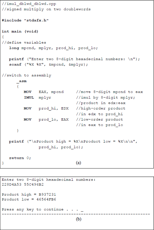
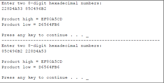
Doubleword multiplication using the one-operand form of IMUL: (a) the program and (b) the outputs.
This next program performs unsigned (MUL) and signed (IMUL) multiplication on the same operands. All combinations of the high-order bit will be applied for byte operands, as shown below.
Multiplicand Bit 7 |
Multiplier Bit 7 |
Unsigned Result |
Signed Result |
|---|---|---|---|
0 |
0 |
Positive |
Positive |
0 |
1 |
Positive |
Negative |
1 |
0 |
Positive |
Negative |
1 |
1 |
Positive |
Positive |
The program is shown in Figure 9.23 as an assembly language module embedded in a C program. Two-digit hexadecimal numbers are entered from the keyboard for both the multiplicand and the multiplier. The multiply instructions are applied, then the results are displayed as unsigned and signed products in decimal notation.
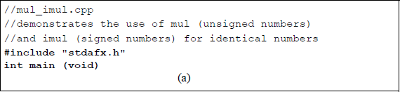
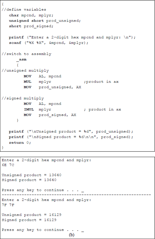
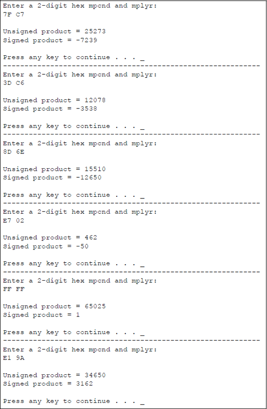
Program to illustrate unsigned and signed multiplication for identical numbers: (a) the program and (b) the outputs.
Multiplication can also be achieved by shifting the operand left a specified number of bits, as shown in Chapter 8. A left shift of one bit position multiplies the operand by two; a left shift of two bit positions multiplies the operand by four; a left shift of three bit positions multiplies the operand by eight, and so forth.
9.4 Division
Division is essentially the inverse of multiplication, where the 2n-bit dividend corresponds to the 2n-bit product; the n-bit divisor corresponds to the n-bit multiplicand; and the n-bit quotient corresponds to the n-bit multiplier. The equation that represents this concept is shown below and includes the n-bit remainder as one of the variables.
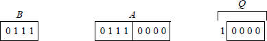
Unlike multiplication, division is not commutative; that is, , except when , where A and B are the dividend and divisor, respectively. Before introducing the divide instructions, this section presents an example of division using the paper-and-pencil method of sequential shift-subtract/add restoring division. Using this algorithm, the dividend is shifted left one bit position, then the divisor is subtracted from the shifted dividend by adding the 2s complement of the divisor. In general, the operands are as shown below, where A is the 2n-bit dividend and B is the n-bit divisor. The quotient is Q and the remainder is R, both of which are n bits.
Overflow will occur if the high-order half of the dividend is greater than or equal to the divisor. For example, assume that the high-order half of the dividend is equal to the divisor, as shown below for a dividend of 112 and a divisor of 7, yielding a quotient of 16. The resulting quotient value of 16 cannot be contained in the machine's word size of four bits; therefore, an overflow had occurred. If the high-order half of the dividend is greater than the divisor, then the value of the quotient will be even greater.
Overflow can be detected by subtracting the divisor from the high-order half of the dividend before the division operation commences. If the result is positive, then an overflow will occur. An overflow is indicated by a divide error exception.
Figure 9.24 illustrates an example of dividing an 8-bit dividend (13) by a 4-bit divisor (5) to yield a 4-bit quotient (2) and a 4-bit remainder (3). Since there are four bits in the divisor, there are four left-shift operations each followed by a subtract operation. The carry-out of the subtraction is placed in the low-order bit position vacated by the left-shifted partial remainder.
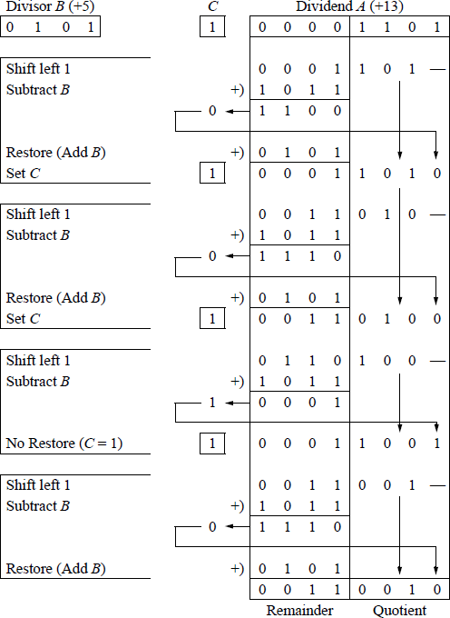
A carry-out of 0 indicates that the difference was greater than the divisor and the partial remainder must be restored by adding the divisor to the partial remainder. A carry-out of 1 indicates that the difference requires no restoration. At the completion of the final cycle, the remainder is contained in the high-order half of the dividend and the quotient is contained in the low-order half of the dividend.
9.4.1 Unsigned Divide (DIV) Instruction
The DIV instruction is one of two divide instructions for fixed-point division; the other is signed divide (IDIV), which is presented in the next section. The DIV instruction divides the unsigned dividend in an implied general-purpose register by the unsigned divisor source operand in a register or memory location. The results are stored in the implied registers. The syntax for the DIV instruction is shown below.
DIV register/memory
The locations of the DIV operands are as follows: the dividend registers are AX, DX:AX, EDX:EAX, and RDX:RAX and the size of the corresponding divisors are 8 bits, 16 bits, 32 bits, and 64 bits, respectively; the resulting quotients are stored in registers AL, AX, EAX, and RAX, respectively; the resulting remainders are stored in registers AH, DX, EDX, and RDX, respectively. If an REX prefix is used in 64-bit mode, the number of general-purpose registers is increased from eight to sixteen and can be extended to 64 bits. Results that are not integers are truncated to integers. The above descriptions are illustrated in Figure 9.25 for 8 bit, 16 bit, and 32 bit divisors.
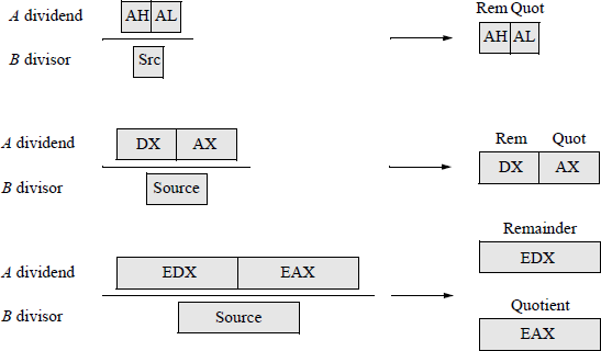
Figure 9.26 shows an assembly language module embedded in a C program that illustrates the DIV instruction. Register pair DX:AX contains the dividend, which is entered from the keyboard as dvdnd_hi (DX) and dvdnd_lo (AX). The divisor is also entered from the keyboard. The dividend, divisor, quotient, and remainder are displayed after the program has executed. The following flags are undefined: OF, SF, ZF, AF, PF, and CF.
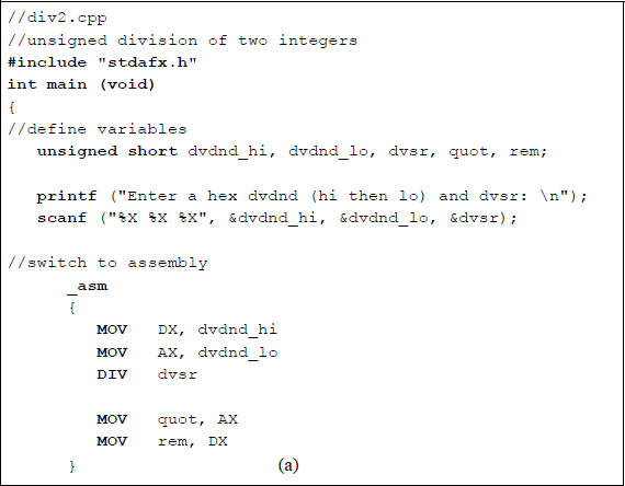
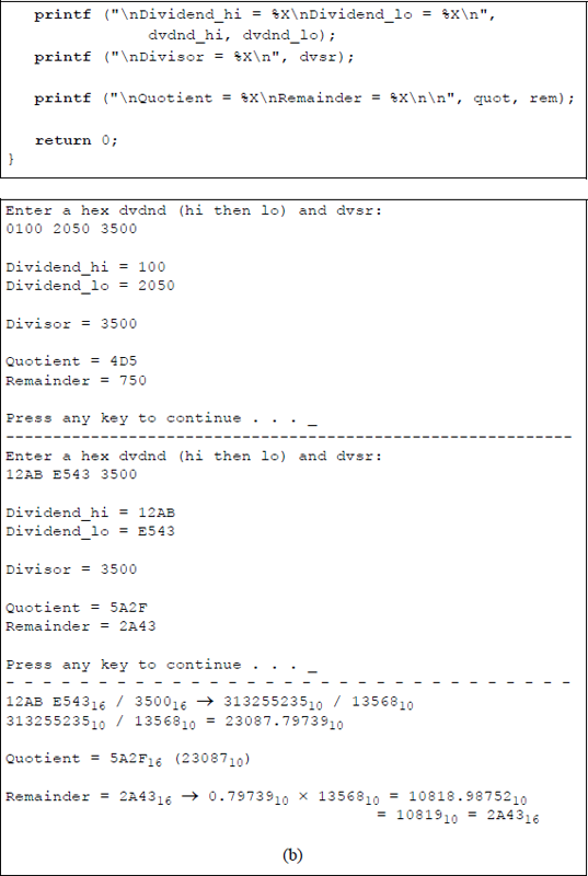
Unsigned division with the dividend in register pair DX:AX: (a) the program and (b) the outputs.
The first set of operands is entered as: and to yield a and a . The calculations shown below illustrate the division operation and show the resulting quotient and remainder.
9.4.2 Signed Divide (IDIV) Instruction
The signed divide instruction (IDIV) is similar to the unsigned divide instruction (DIV), except that IDIV operates on signed operands. The IDIV instruction divides the signed dividend in registers AH:AL, DX:AX, EDX:EAX, or RDX:RAX (if an REX prefix is used in 64-bit mode) by the signed source divisor and stores the resulting quotient in the low-order part of the register pairs and stores the remainder in the high-order part of the register pairs.
The source operand can be in a general-purpose register or in a memory location. Results that are not integers are truncated toward zero as integers. The registers shown in Figure 9.25 also apply to the IDIV instruction. The following flags are undefined: OF, SF, ZF, AF, PF, and CF. The syntax for the IDIV instruction is shown below.
IDIV register/memory
The remainder has the same sign as the dividend and satisfies the following equation as shown in the examples of Figure 9.27:
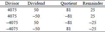
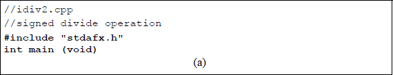
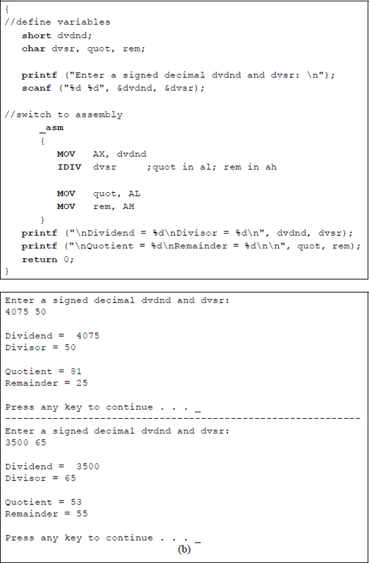
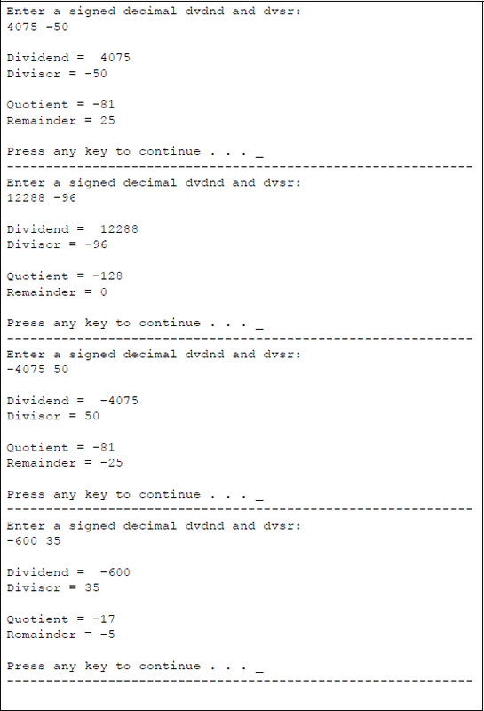
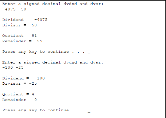
Figure 9.28 shows an assembly language module embedded in a C program that illustrates the application of the IDIV instruction. The dividend and divisor are entered from the keyboard as signed decimal integers. All combinations of the signs are presented for the dividend and divisor. The quotient and remainder are displayed after the program has executed.
Division can also be achieved by shifting the operand right a specified number of bits, as shown in Chapter 8. A right shift of one bit position divides the operand by two; a right shift of two bit positions divides the operand by four; a right shift of three bit positions divides the operand by eight, and so forth. All of the problems in the following section utilize one or more of the instructions presented in this chapter.
9.5 Problems
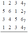
9.1 Add the following numbers, which are in radix complementation for radix 7.
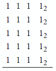
9.2 Add the following numbers, which are in radix complementation for radix 2.
9.3 Indicate whether an overflow occurs for the operation shown below. The numbers are in radix complementation for radix 3.
9.4 Write a program segment to negate a 32-bit binary number. The number is in 2s complement representation and resides in register pair DX: AX. Do not use the NEG instruction.
9.5 Let and the word OPND in . Determine whether the conditional jump instructions shown below will jump to DEST.
(a) ADD AX, 200JS DEST(b) ADD OPND, 200JZ DEST9.6 Determine the contents of registers AL and BL after the program segment shown below has executed. Then write an assembly language module embedded in a C program to verify the results.
MOV AL, 00HMOV BL, -5LOOP1: ADD BL, 2INC ALADD BL, -1JNZ LOOP19.7 Let and , then add the two registers and obtain the state of the following flags: AF, CF, OF, PF, SF, and ZF.
9.8 Write an assembly language module — not embedded in a C program — that requests two characters to be entered from the keyboard. Display the first character unchanged and display the second character shifted left logically one bit position. The characters can be numbers or special characters in the range 21H to 3FH.
9.9 Write an assembly language program — not embedded in a C program — that removes all nonletters from a string of characters that are entered from the keyboard.
9.10 Write an assembly language module embedded in a C program that adds two 4-digit hexadecimal numbers and displays the sum and the low-order two bytes of the EFLAGS register.
9.11 Write an assembly language module embedded in a C program that uses the add with carry (ADC) instruction in the addition of four 4-digit hexadecimal numbers: two for the augend and two for the addend. Display the high-order sum and the low-order sum. Also display the high-order byte and the low-order byte of the EFLAGS register.
9.12 Given the program shown below, determine the contents of the RSLT field after each of the following hexadecimal characters are entered from the keyboard:
;logic_inc.asm;-----------------------------------------------------;STACK
;-----------------------------------------------------.DATAPARLST LABEL BYTEMAXLEN DB 15ACTLEN DB ?OPFLD DB 15 DUP(?)PRMPT DB 0DH, 0AH, 'Enter text: $'RSLT DB 0DH, 0AH, 'Result = $'
;-----------------------------------------------------.CODEBEGIN PROC FAR
;set up pgm dsMOV AX, @DATAMOV DS, AX
;read promptMOV AH, 09HLEA DX, PRMPTINT 21H
;keyboard request rtn to enter charactersMOV AH, 0AHLEA DX, PARLSTINT 21H
;set up addressesLEA SI, OPFLDLEA DI, OPFLD+2LEA BX, RSLT+12MOV CX, 4
;begin main pgmLP1: MOV AL, [SI]MOV AH, [DI]XOR AL, AHOR AL, 30HMOV [BX] ,ALINC SIINC DIINC BXLOOP LP1
;display resultMOV AH, 09HLEA DX, RSLTINT 21H
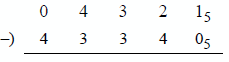
BEGIN ENDPEND BEGIN9.13 Perform a subtract operation on the radix 5 numbers shown below. The procedure is identical to the radix 2 method — the only difference is the radix.
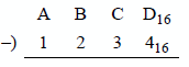
9.14 Perform a subtract operation on the two hexadecimal operands shown below.
9.15 Indicate whether an overflow occurs for the operation shown below. The numbers are in radix complement representation for radix 2.
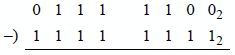
9.16 Indicate whether an overflow occurs for the operation shown below. The numbers are in radix complement representation for radix 2.
9.17 Let register . Then execute the instruction shown below to obtain the difference and the state of the following flags: OF, SF, ZF, AF, PF, and CF.
SUB AL, 65H9.18 Let register and register . Then execute the instruction shown below to obtain the difference and the state of the following flags: OF, SF, ZF, AF, PF, and CF.
SUB DL, BH9.19 Determine the contents of register AL after the program shown below has executed.
//decrement.cpp//program to illustrate the DEC instruction.
#include "stdafx.h"
int main (void){
//define variableschar result;
//switch to assembly_asm{MOV AL, 3AHMOV CH, 0A9HADD CH, 06HADD AL, CH
NEG ALDEC ALMOV result, AL}
printf ("\nAL = %X\n\n", result);
return 0;}9.20 Show the result of the program listed below when the following digits are entered from the keyboard: 34689000678305. Refer to Chapter 10 for a description of the ASCII Adjust After Addition (AAA) instruction.
PAGE 66, 80;adc_aaa_dec.asm
;-----------------------------------------------------.STACK
;-----------------------------------------------------.DATAPARLST LABEL BYTEMAXLEN DB 20ACTLEN DB ?OPFLD DB 20 DUP(?)PRMPT DB 0DH, 0AH, 'Enter 14 single-digit numbers: $'RSLT DB 0DH, 0AH, 'Result = $';OPFLD #s 34689000678305
;-----------------------------------------------------.CODEBEGIN PROC FAR
;set up pgm dsMOV AX, @DATAMOV DS, AX
;read promptMOV AH, 09HLEA DX, PRMPTINT 21H
;keyboard request rtn to enter charactersMOV AH, 0AHLEA DX, PARLSTINT 21H;start main pgmLEA SI, OPFLD+5LEA DI, OPFLD+13LEA BX, RSLT+12
MOV CX, 6CLCLP1: MOV AH, 0MOV AL, [SI]ADC AL, [DI]AAAOR AL, 30HMOV [BX], ALDEC SIDEC DIINC BXLOOP LP1
MOV AH, 09HLEA DX, RSLTINT 21H
BEGIN ENDPEND BEGIN9.21 Write an assembly language program — not embedded in a C program — to reverse the order and change to uppercase all letters that are entered from the keyboard. The letters that are entered may be lowercase or uppercase.
9.22 Eight digits, either 0 or 1, are entered from the keyboard. Write an assembly language program — not embedded in a C program — to determine the parity of the byte. If there are an even number of 1s in the byte, then a flag bit (PF) is set to a value of 1 maintaining odd parity over all nine bits — the eight bits plus the parity flag; otherwise, the parity flag is reset to 0. Display the parity flag. Draw a flowchart that represents the operation of the odd parity generator. Remember that a 0 and a 1 are represented in ASCII as 30H and 31H, respectively.
9.23 Write an assembly language program — not embedded in a C program — to sort n single-digit numbers in ascending numerical order that are entered from the keyboard. A simple exchange sort is sufficient for this program. The technique is slow, but appropriate for sorting small lists. The method is as follows:
Search the list to find the smallest number.
After finding the smallest number, exchange this number with the first number.
Search the list again to find the next smallest number, starting with the second number.
Then exchange this (second smallest) number with the second number.
Repeat this process, starting with the third number, then the fourth number, and so forth.
9.24 Let register and register . After execution of
IMUL BLdetermine the hexadecimal contents of register AX.
9.25 Determine the contents of register pair DX:AX after the following program segment has been executed:
OPl DW 8080HOP2 DB 0A2HMOV AL, OP2CBWMUL OPl- 9.26 Determine the results of each of the following operations:
Before |
Instruction |
||||
|---|---|---|---|---|---|
AX |
= |
FF |
FFH |
MUL |
AX |
AX |
= |
FF |
E4H |
MUL |
BX |
BX |
= |
04 |
C2H |
||
AX |
= |
00 |
17H |
IMUL |
CX |
CX |
= |
00 |
B2H |
||
AX |
= |
FF |
E4H |
IMUL |
BX |
BX |
= |
04 |
C2H |
||
9.27 Determine the hexadecimal contents of register AX after the following program segment has been executed:
MOV CX, 3MOV AX, 2LP1: MUL AXLOOP LP19.28 Write an assembly language module embedded in a C program that multiplies two unsigned (MUL) hexadecimal numbers. Enter numbers from the keyboard that produce a product where the high-order half is all zeroes and where the high-order half is not all zeroes. The overflow flag and the carry flag should be set if the high-order half of the product is not all zeroes. Display the products and the low-order 16 bits of the EFLAGS register.
9.29 Perform a signed multiplication (IMUL) on two doubleword operands: a negative multiplicand with a hexadecimal value of 85C496B216 and a positive multiplier with a hexadecimal value of 2244124316. Use the paper-and-pencil method and display all of the partial products. Then verify the product using an assembly language module embedded in a C program in which the operands are entered from the keyboard.
9.30 Write an assembly language module embedded in a C program that uses the three-operand form for signed multiplication. Enter a signed decimal multiplicand from the keyboard and assign an immediate multiplier for the IMUL operation. Display the multiplicand, the multiplier, and the product.
9.31 Use the shift logical left (SHL) instruction in an assembly language module embedded in a C program to multiply an operand. Enter an 8-digit hexadecimal number and a shift amount from the keyboard. Include numbers and shift amounts that produce no overflow and that produce an overflow. Display the shift amount, the preshifted value, the postshifted value, and the accompanying flags.
- 9.32 Determine the result of the following operation:
Before |
Instruction |
|---|---|
AX = FE 01H |
DIV BL |
BL = FFH |
9.33 Determine whether the following operands produce an overflow for an unsigned binary divide (DIV) operation:
(a) Dividend = 00011111
Divisor = 0001
(b) Dividend = 00001111
Divisor = 0001
(c) Dividend = 01000001
Divisor = 0011
9.34 Write an assembly language module embedded in a C program to perform unsigned division (DIV) on two decimal integers that are entered from the keyboard. Print the dividend, divisor, quotient, and remainder.
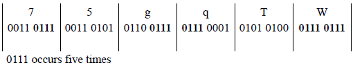
9.35 Write an assembly language program — not embedded in a C program — for a sequence detector that detects the number of times that the four-bit sequence 0111 appears in the keyboard input buffer (OPFLD) when n characters are entered. The variable n has the following range: 1 ≤ n ≤ 30.
The bit configuration 0111 may be in the high-order four bits of the keyboard character, the low-order four bits, or both high- and low-order four bits. Display the number of times that the sequence occurs. The DIV instruction can be used in this program. Draw a flowchart prior to designing the program. An example of input data is shown below.
9.36 Write an assembly language program — not embedded in a C program — that calculates the surface area of a rectangular solid box. The length, width, and height are single-digit numbers that are entered from the keyboard. The program will use the ADD, MUL, and DIV instructions. Enter at least three sets of numbers and display the corresponding surface area.
9.37 Determine the contents of register pair DX:AX for parts (a) and (b) after execution of the following program segment:
MOV AX, dvdndCWDIDIV dvsr(a) dvdnd = 059A; dvsr = FFC7
(b) dvdnd = 7C58; dvsr = FFA9
9.38 Write an assembly language module embedded in a C program that evaluates the expression shown below, where , , , and .