Table of Contents for
X86 Assembly Language and C Fundamentals
 X86 Assembly Language and C Fundamentals
Published by
CRC Press, 2015
X86 Assembly Language and C Fundamentals
Published by
CRC Press, 2015
- X86 Assembly Language and C Fundamentals
- Preliminaries
- By the same Author
- X86 Assembly Language and C Fundamentals
- X86 Assembly Language and C Fundamentals
- Preface
- Chapter 1 Number Systems and Number Representations
- Chapter 2 X86 Processor Architecture
- Chapter 3 Addressing Modes
- Chapter 4 C Programming Fundamentals
- Chapter 5 Data Transfer Instructions
- Chapter 6 Branching and Looping Instructions
- Chapter 7 Stack Operations
- Chapter 8 Logical, Bit, Shift, and Rotate Instructions
- Chapter 9 Fixed-Point Arithmetic Instructions
- Chapter 10 Binary-Coded Decimal Arithmetic Instructions
- Chapter 11 Floating-Point Arithmetic Instructions
- Chapter 12 Procedures
- Chapter 13 String Instructions
- Chapter 14 Arrays
- Chapter 15 Macros
- Chapter 16 Interrupts and Input/Output Operations
- Chapter 17 Additional Programming Examples
- Appendix A ASCII Character Codes
- Appendix B Answers to Select Problems
Chapter 7
Stack Operations
The stack is a one-dimensional data structure located in contiguous locations of memory that is used for the temporary storage of data. It is one of the segments in a segmented memory model and is called the stack segment, in which the base address of the stack is contained in the stack segment (SS) register. A stack can have a maximum size of four gigabytes. A general-purpose register (GPR) called the stack pointer (E)SP contains the address of the current top of stack. A stack is comparable to a stack of trays in a cafeteria in which each tray is stacked on top of the last tray; the tray on the top of the stack is the tray that is normally removed first.
Generally, only the word at the top of stack — pointed to by the stack pointer — is accessed; however, another GPR can also be used to access elements within the stack. This is the base pointer (E)BP register, which contains an offset into the stack segment to reference data or parameters that were passed to a called program via the stack. The default segment for the (E)BP register is the stack segment. Since the element at the top of the stack is removed first, stacks are referred to as a last-in-first-out (LIFO) queue.
A data element is placed on top of the stack by a PUSH instruction; a data element is removed from the top of the stack by a POP instruction. A stack builds toward lower addresses. When a data item is pushed onto the stack, the (E)SP register is first decremented, then the data item is stored at the new top of stack. When a data item is popped off the stack, it is first stored in the destination address, then the (E)SP register is incremented to point to the new top of stack. The operand size determines the amount that the stack pointer is incremented or decremented. For example, if the operand size is 16 bits, then the SP register is incremented/decremented by 2; if the operand size is 32 bits, then the ESP register is incremented/decremented by 4.
7.1 Stack Structure
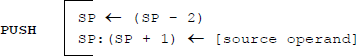
Figure 7.1 shows a drawing of a stack structure where the operand size is 16 bits; therefore, the SP register is used as the stack pointer. The structure is similar for an operand size of 32 bits where the items stored on the stack are doublewords; in this case, the stack pointer is the ESP register. In Figure 7.1, a PUSH operation first decrements SP by 2, then stores the operand at the new stack top, as shown below, where the colon (:) indicates concatenation.
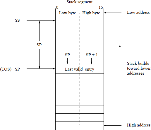
A POP operation first stores the operand in the destination then increments SP by 2, as shown below.
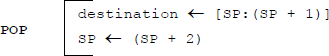
Figure 7.2 shows an example of pushing and popping 16-registers using the stack configuration of Figure 7.1. Prior to the operations, the general-purpose register, AX, is assigned a value of 1234H; the stack segment register, SS, is assigned a value of 1050H; and the stack pointer register, SP, is assigned a value of 0008H. Figure 7.2(a) shows the initialization of the stack and registers. Figure 7.2(b) shows the PUSH AX operation; Figure 7.2(c) shows the POP AX operation; and Figure 7.2(d) shows the POP BX operation. The stack pointer is incremented or decremented accordingly for each operation. Flags are not affected by the PUSH and POP operations.
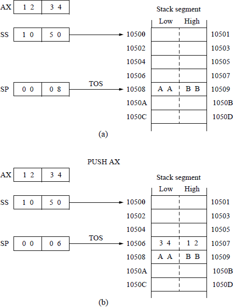
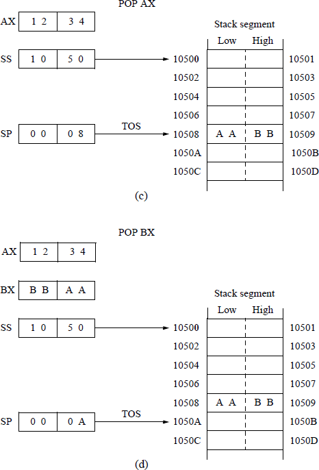
Diagram showing stack operations for PUSH and POP instructions involving the general-purpose registers AX and BX: (a) initialization, (b) PUSH AX, (c) POP AX, and (d) POP BX.
Unlike the CS register, the SS register and the (E)SP register can be initialized explicitly. This allows multiple stacks to be used with the capability to switch between the stacks. This is a useful technique for multitasking systems, where each task has a separate stack. One method of initializing a stack is shown in Figure 7.3 to initialize the SS register and the SP register.

One technique to initialize the SS register and the SP register: (a) the stack structure and (b) the program snippet.
The memory model is defined as SMALL by the .MODEL directive, which defines a code segment of ≤ 64 kilobytes and a data segment of ≤ 64 kilobytes. The stack is defined as 64 bytes by the .STACK directive — the default stack size is 1,024 bytes. Initially, (E)SP points to the doubleword/word that is one location higher than the highest address in the stack.
The name TOS in the stack segment is characterized by LABEL, which is a directive used to define the type attribute of a name — in this case the name TOS is defined as type WORD and aligns the stack on a word boundary. The syntax for the LABEL directive is shown below.
NAME LABEL type-specifier
Figure 7.3 established the SS register and the SP register using the MOV instruction. They can also be established in a simpler more direct method by using the load far pointer using SS (LSS) instruction. The LSS instruction loads a far pointer, containing a segment selector and offset, from the source operand in memory into the SS register and the (E)SP register in one operation. The syntax for the LSS instruction is shown below for legacy mode, with different operand-size attributes.
LSS register 16 bits, memory 16:16 bits
LSS register 32 bits, memory 16:32 bits
The operation code (LSS) and the destination specify the stack segment and the general-purpose register (E)SP. The 16-bit segment selector from the source operand is loaded into the stack segment (SS) register and the 32-bit or 16-bit offset is loaded into the stack pointer (E)SP register as specified by the destination operand. The following line of code establishes the SS register and the SP register.
LSS SP, [SRC_OPND]
The stack pointer (SP) register should point to a 16-bit word or a 32-bit doubleword boundary for correct alignment, as specified by the stack segment. The PUSH instruction can push memory operands, immediate operands, general-purpose registers, and segment registers onto the stack. The POP instruction stores the word or doubleword to a general-purpose register, a segment register, or a memory location. When an operand is popped off the stack and stored in the destination, it is simply copied to the destination, not removed from the stack until it is overwritten.
If an attempt is made to push an operand onto a full stack, then an error is indicated; likewise, if an attempt is made to pop an empty stack, then an error is indicated. Most operating systems monitor the stack boundaries to detect stack overflow and stack underflow in order to maintain system reliability.
However, if necessary, a safe push and a safe pop can be implemented in software. Assume that the boundary addresses for a stack are 00986 to 10500. If (E)SP is ≤ 00986, and a push operation is attempted, then a stack overflow is indicated, because the stack is full. Similarly, if (E)SP is > 10500, and a pop operation is attempted, then a stack underflow is indicated, because the stack is empty. The code snippets shown check for stack overflow and stack underflow.
Stack overflow: CMP 00986, ESP
JLE FULL_ERR
NEXT_INSTRStack underflow: CMP 10500, ESP
JG EMPTY_ERR
NEXT_INSTR
Figure 7.4 shows an assembly language module embedded in a C program to illustrate stack utilization to perform addition operations on user-entered integers. This is a rudimentary application of a stack, but adequate to describe the use of a stack. The user enters three integers, int1, int2, and int3, which are moved to registers EAX, EBX, and ECX, respectively. The program then adds int1 and int2 and stores the sum in register EAX, then moves the sum to location sum_12 to be displayed later.
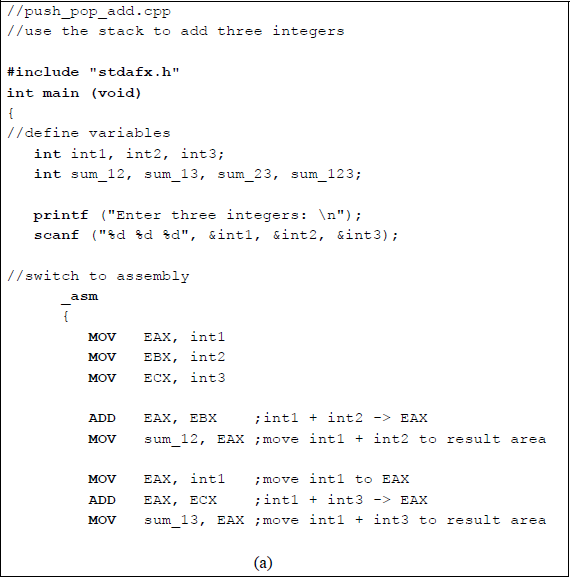
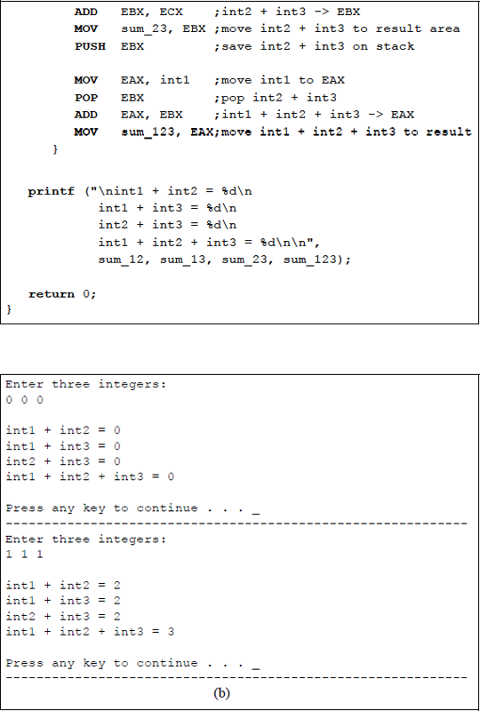
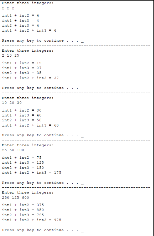
Program to illustrate using a stack to add three integers: (a) the program and (b) the outputs.
Then int1 and int3 are added; the sum is stored in register EAX and location sum_13. Then int2 and int3 are added; the sum is stored in register EBX, and location sum_23. Register EBX is then pushed onto the stack. Integer int1 is moved to register EAX, register EBX (int2 + int3) is popped off the stack and added to register EAX, which contains int1, to produce the sum of the three integers: int1, int2, and int3. The program then prints the following sums: int1 + int2, int1 + int3, int2 + int3, and int1 + int2 + int3.
7.2 Additional Push Instructions
This section describes additional push instructions, such as PUSHA, PUSHAD, PUSHF, and PUSHFD. These instructions push specific source operands onto the stack. The stack pointer, (E)SP register, operates in the same manner as the regular PUSH operation; that is, it decrements an explicit number of bytes before the push operation, depending on the size of the operand being pushed onto the stack.
Push all 16-bit general-purpose registers (PUSHA) The PUSHA instruction is used to push all general-purpose registers (GPRs) onto the stack. If the operand-size attribute is 16, then the registers are pushed onto the stack in the following order: AX, CX, DX, BX, SP, BP, SI, and DI. Note that the value in SP that is pushed onto the stack is the value in SP before the PUSHA instruction is executed.
When a procedure call is executed, the processor does not automatically save the GPRs onto the stack prior to executing the call. The PUSHA instruction is one way that the calling/called procedure can save all the GPRs by executing a single instruction. The called procedure can also save only the specific registers that will be used before executing the procedure; the registers are then restored to their original values prior to returning to the calling program. No flags are affected by the PUSHA instruction.
Push all 32-bit general-purpose registers (PUSHAD) The instruction that pushes all 32-bit GPRs onto the stack is the PUSHAD instruction. If the operand-size attribute is 32 bits, then the registers are pushed onto the stack in the following order: EAX, ECX, EDX, EBX, ESP, EBP, ESI, and EDI. Note that the value in ESP that is pushed onto the stack is the value in ESP before the PUSHAD instruction is executed. The PUSHA and PUSHAD instructions have the same operation code and their operation is identical except for the registers that are pushed onto the stack, which are a function of the operand-size attribute.
When a procedure is called, saving the GPRs is identical as described under the PUSHA heading. It should be noted that some X86 assemblers may cause the operand size to be 16 bits for a PUSHA instruction or to be 32 bits when a PUSHAD instruction is encountered. Other X86 assemblers use the current value of the operand-size attribute. No flags are affected by the PUSHAD instruction.
Push 16 low-order flags (PUSHF) This instruction pushes the FLAGS register — the low-order 16 bits of the EFLAGS register — onto the stack if the operand-size attribute is 16 bits, then decrements the stack pointer, SP, by two. The FLAGS register contains the status flags (OF, SF, ZF, AP, PF, and CF), the control flag (DF), and four system flags (NT, IOPL, IF, and TF). No flags are affected by the PUSHF instruction.
Push all 32 flags (PUSHFD) This instruction pushes the 32-bit EFLAGS register onto the stack if the operand-size attribute is 32 bits, then decrements the stack pointer, ESP, by four. The EFLAGS register contains the status flags (OF, SF, ZF, AP, PF, and CF), the control flag (DF), and the ten system flags (ID, VIP, VIF, AC, VM, RF, NT, IOPL, IF, and TF).
Some X86 assemblers may cause the operand size to be 16 bits for a PUSHF instruction or to be 32 bits when a PUSHFD instruction is encountered. Other X86 assemblers use the current value of the operand-size attribute. The PUSHF and PUSHFD instructions have the same operation code and their operation is identical except for the registers — FLAGS or EFLAGS — that are pushed onto the stack, which are a function of the operand-size attribute. No flags are affected by the PUSHFD instruction. Certain flags in the EFLAGS register can be modified by specific instructions; for example, set carry flag (STC), clear carry flag (CLC), and complement carry flag (CMC).
7.3 Additional Pop Instructions
This section describes additional pop instructions, such as POPA, POPAD, POPF, and POPFD. The stack pointer, (E)SP, register operates in an identical manner as for the regular POP operation; that is, it increments an explicit number of bytes after the pop operation depending on the size of the operand being popped from the stack.
Pop all 16-bit general-purpose registers (POPA) The POPA instruction is used to pop all general-purpose registers off the stack. If the operand-size attribute is 16, then the word registers are popped off the stack in the following order and stored in their respective registers: DI, SI, BP, the pushed SP is ignored, BX, DX, CX, and AX. Note that the value in SP is discarded, because if SP were popped off the stack, then the value in the current SP register would be changed.
The POPA instruction is one way that the called/calling procedure can restore all the GPRs by executing a single instruction. The called procedure can also restore only the specific registers that were used in the procedure; the registers are then restored to their original values prior to returning to the calling program. The POPA instruction effectively reverses the operation of the PUSHA instruction. No flags are affected by the POPA instruction.
Pop all 32-bit general-purpose registers (POPAD) The POPAD instruction pops all 32-bit general-purpose registers off the stack. If the operand-size attribute is 32 bits, then the registers are popped off the stack in the following order: EDI, ESI, EBP, the pushed ESP is ignored, EBX, EDX, ECX, and EAX. Note that the value in ESP is discarded for the same reason that the value of SP was discarded for the POPA instruction. The POPA and POPAD instructions have the same operation code and their operation is identical except for the registers that are popped off the stack, which are a function of the operand-size attribute.
Some X86 assemblers may cause the operand size to be 16 bits for a POPA instruction or to be 32 bits when a POPAD instruction is encountered. Other X86 assemblers use the current value of the operand-size attribute. No flags are affected by the POPAD instruction.
Pop 16 low-order flags (POPF) The POPF instruction is used when the operand-size attribute is 16. It pops the top word from the stack into the low-order 16 bits of the EFLAGS register, then increments the SP register by two to point to the new stack top. The POPF instruction, in conjunction with the PUSHF instruction, allows a procedure to save the calling program's flags and then to restore the flags. The following flag bits are affected: OF, DF, TF, SF, ZF, AF, PF, and CF. The IOPL flag and the IF flag are also affected depending on the privilege level.
Pop all 32 flags (POPFD) The POPFD instruction pops a doubleword off the stack into the EFLAGS register if the operand-size attribute is 32 bits, then increments the ESP stack pointer by four. The POPF and POPFD instructions have the same operation code and their operation is identical except for the registers that are loaded from the stack — FLAGS or EFLAGS — which are a function of the operand-size attribute. Some X86 assemblers may cause the operand size to be 16 bits for a POPF instruction or to be 32 bits when a POPFD instruction is encountered. Other X86 assemblers use the current value of the operand-size attribute.
7.4 Problems
7.1 Given DS = 2800H, BX = 0400H, SP = 1000H, SS = 2F00H, and memory location 28400H = A020H, find the real (physical) data address of the source operand and the real address of the stack top when the PUSH [BX] instruction is executed. Show the contents of the stack top in memory and determine the new contents of the stack pointer SP.
7.2 Given DS = FF00H, SI = 0008H, SP = 0FEAH, SS = 2F00H, and memory location 2FFEAH = 3BC5H, find the real (physical) data address of the destination operand and the real address of the stack top when the POP [SI] instruction is executed. Show the contents of the stack top in memory and determine the new contents of the stack pointer SP.
7.3 Determine the result of each instruction for the following program segment:
PUSH EBPMOV EBP, ESPPUSH EAXPUSH EBXPUSH ECX. . .. . .MOV EAX, [EBP – 12]MOV EBX, [EBP – 8]MOV ECX, [EBP – 4]. . .ADD ESP, 12POP EBP7.4 Determine the result of each instruction for the following program segment:
PUSH EAXPUSH EBXPUSH ECXPUSH EBPMOV EBP, ESP. . .MOV EAX, [EBP + 4]MOV EBX, [EBP + 8]MOV ECX, [EBP + 12]. . .POP EBPADD ESP, 127.5 The partial contents of a stack are shown below before execution of the program segment listed below. Determine the contents of the stack after the program has been executed and indicate the new top of stack.
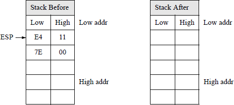
POP BXMOV AH, BHADD AH, BLMOV BH, AHPUSH BX7.6 Why will a PUSH AL instruction cause an error message to be displayed?
7.7 Assume that a stack contains three parameters and that SP points to the third parameter, as shown in the diagram below. Determine how each parameter can be accessed if the following program segment is executed:
PUSH BPPUSH CXPUSH SIMOV BP, SP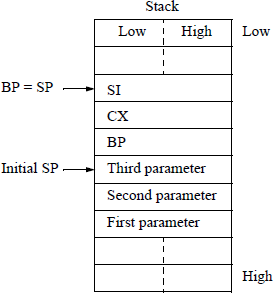
7.8 Write an assembly language program — using the PUSH and POP instructions — that adds four decimal integers, then displays their sum. Embed the assembly module in a C program. The decimal integers are entered from the keyboard.
7.9 Write an assembly language program — using the PUSH and POP instructions — that adds five hexadecimal integers, then displays their sum. Embed the assembly module in a C program. The hexadecimal integers are entered from the keyboard. Enter hexadecimal integers that range from one character to eight characters. Display the sum as upper-case hexadecimal characters.