Table of Contents for
X86 Assembly Language and C Fundamentals
 X86 Assembly Language and C Fundamentals
Published by
CRC Press, 2015
X86 Assembly Language and C Fundamentals
Published by
CRC Press, 2015
- X86 Assembly Language and C Fundamentals
- Preliminaries
- By the same Author
- X86 Assembly Language and C Fundamentals
- X86 Assembly Language and C Fundamentals
- Preface
- Chapter 1 Number Systems and Number Representations
- Chapter 2 X86 Processor Architecture
- Chapter 3 Addressing Modes
- Chapter 4 C Programming Fundamentals
- Chapter 5 Data Transfer Instructions
- Chapter 6 Branching and Looping Instructions
- Chapter 7 Stack Operations
- Chapter 8 Logical, Bit, Shift, and Rotate Instructions
- Chapter 9 Fixed-Point Arithmetic Instructions
- Chapter 10 Binary-Coded Decimal Arithmetic Instructions
- Chapter 11 Floating-Point Arithmetic Instructions
- Chapter 12 Procedures
- Chapter 13 String Instructions
- Chapter 14 Arrays
- Chapter 15 Macros
- Chapter 16 Interrupts and Input/Output Operations
- Chapter 17 Additional Programming Examples
- Appendix A ASCII Character Codes
- Appendix B Answers to Select Problems
Chapter 10
Binary-Coded Decimal Arithmetic Instructions
The radix is 10 in the decimal number system; therefore, ten digits are used, 0 through 9. The low-value digit is 0 and the high-value digit is (r – 1) = 9. The weight assigned to each position of a decimal number is as follows:
where the integer and fraction are separated by the radix point (decimal point).
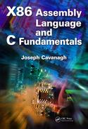
Binary-coded decimal (BCD) instructions operate on decimal numbers that are encoded as 4-bit binary numbers in the 8421 code. For example, the decimal number 576 is encoded in BCD as 0101 0111 0110. BCD numbers have a range of 0 to 9; therefore, any number greater than 9 must be adjusted by adding a value of 6 to the number to yield a valid BCD number. For example, if the result of an operation is 1010, then 0110 is added to this intermediate sum. This yields a value of 0000 with a carry of 1, or 0001 0000 in BCD which is 10 in decimal.
The condition for a correction (adjustment) of an intermediate sum that also produces a carry-out is shown in Equation 10.1. This specifies that a carry-out will be generated whenever bit position b8 is a 1 in both decades, when bit positions b8 and b4 are both 1s, or when bit positions b8 and b2 are both 1s, as shown in the examples of Figure 10.1. Table 10.1 lists the ten decimal digits (0 through 9) and the corresponding binary-coded decimal digits, plus BCD numbers of more than one decimal digit.
Binary-Coded Decimal Numbers
Decimal |
Binary-Coded Decimal |
|---|---|
0 |
0000 |
1 |
0001 |
2 |
0010 |
3 |
0011 |
4 |
0100 |
5 |
0101 |
6 |
0110 |
7 |
0111 |
8 |
1000 |
9 |
1001 |
10 |
0001 0000 |
11 |
0001 0001 |
12 |
0001 0010 |
... |
... |
124 |
0001 0010 0100 |
... |
... |
365 |
0011 0110 0101 |
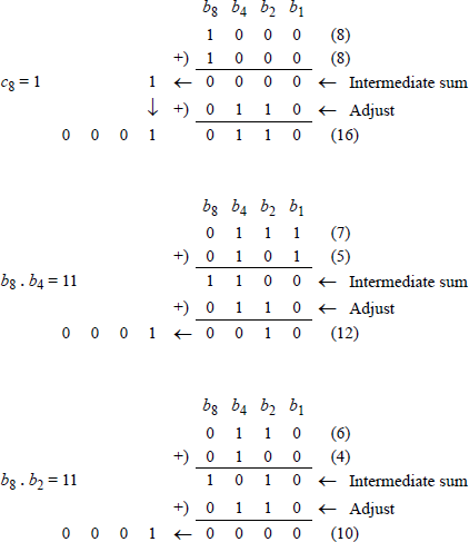
Figure 10.2 shows an additional example of adding BCD numbers, where the augend and addend both contain three digits each: the augend = 436, the addend = 825, to yield a sum of 1261. The intermediate sum in this example is 1 1100 0110 1011. The sum of the second decade does not require adjustment, because the intermediate sum does not satisfy Equation 10.1. The same is true for the final carry-out.
10.1 ASCII Adjust After Addition (AAA) Instruction
The AAA instruction adjusts the result of an addition operation of two unpacked binary-coded decimal (BCD) operands. An unpacked BCD number contains zeroes in the high-order four bits of the byte; the numerical value of the number is contained in the low-order four bits of the byte. General-purpose register AL is the implied source and destination for the AAA instruction.
The sum obtained by the addition of two unpacked BCD or ASCII numbers is stored in register AL. This sum may not be a valid BCD value. The AAA instruction converts the sum in register AL into a valid BCD number and stores the result in bits 3 through 0 of register AL and resets bits 7 through 4 of register AL. If the low-order four bits of the sum in register AL are greater than nine or if the AF flag is set, then six is added to AL and register AH is incremented by 1. In this case, both the auxiliary carry flag (AF) and the carry flag (CF) are set; otherwise, they are reset. The following flags are undefined: OF, SF, ZF, and PF.
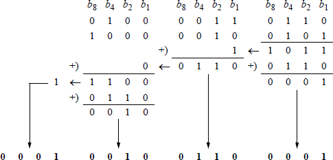
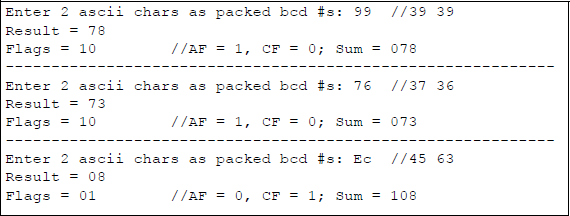
Figure 10.3 shows examples of sums in which the result is not a valid BCD number — greater than nine — and a sum in which the AF flag is set. When used in a program, the AAA instruction is preceded by an ADD instruction or an ADC instruction.
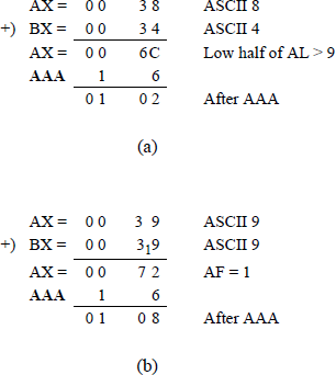
Examples of using the AAA instruction: (a) where the sum was not a valid BCD number and (b) where the AF flag was set.
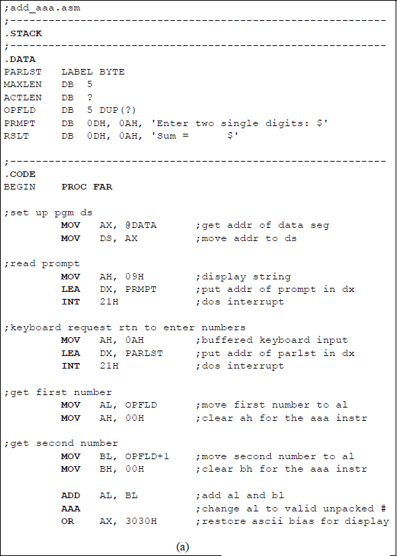
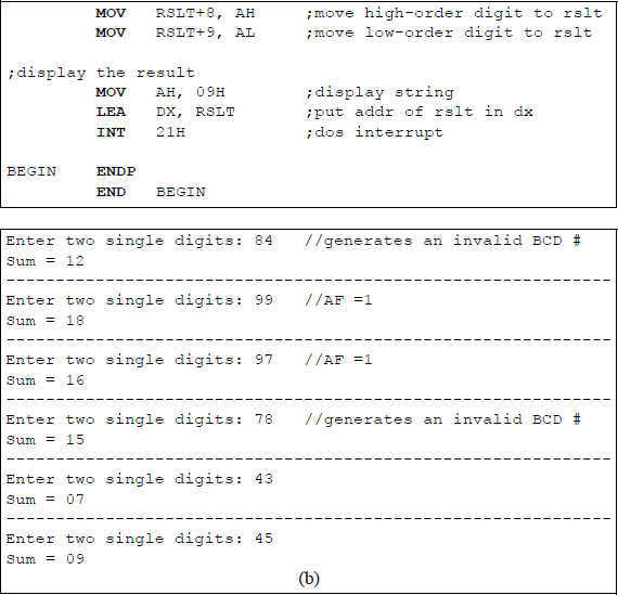
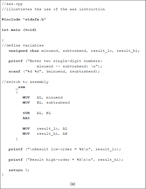
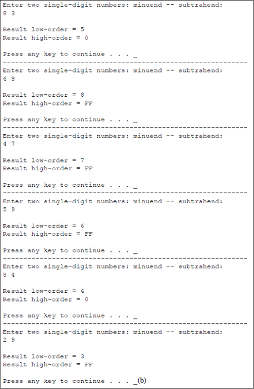
Figure 10.4 shows an assembly language module — not embedded in a C program — that illustrates the use of the AAA instruction. Two single-digit numbers are entered from the keyboard and added using the ADD instruction; then the AAA instruction is executed to produce a valid result, if necessary. Numbers that generate a valid BCD sum are entered, also numbers that generate an invalid BCD result, and numbers that generate an auxiliary carry flag (AF). In order to display the sums correctly, the ASCII bias is added to the sums generated by the AAA instruction. A program that adds two 3-digit numbers is left as a problem.
10.2 Decimal Adjust AL after Addition (DAA) Instruction
The DAA instruction adjusts the sum of two packed BCD integers to generate a packed BCD result. A packed BCD number contains a valid BCD digit in both the high-order four bits and the low-order four bits of a byte. An ADD instruction precedes the DAA instruction. The ADD instruction adds the two packed BCD numbers and stores the sum in register AL. The DAA instruction is then executed and adjusts the sum in register AL to a valid 2-digit packed BCD value, if necessary. Register AL is the implied source and destination register for the DAA instruction.
There are two rules that are used when adding packed BCD numbers regarding the resulting sum.
Rule 1: If the low-order four bits of the sum are greater than nine or if the auxiliary carry flag (AF) is set, then 06H is added to the sum — which is contained in register AL — and the AF flag is set; otherwise, the AF is reset.
Rule 2: If the sum in AL is greater than 9FH or if the carry flag (CF) is set, then 60H is added to AL and the CF flag is set; otherwise, the CF is reset.
For both rules, the overflow flag (OF) is undefined. Examples of adding packed BCD numbers are shown in Figure 10.5.
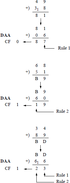
Figure 10.6 shows an assembly language module embedded in a C program that illustrates the application of the DAA instruction. Two hexadecimal numbers are entered from the keyboard: an augend and an addend. They are added using the ADD instruction, then adjusted using the DAA instruction. The sum is then displayed as a valid 2-digit packed BCD result in register AL. Since the carry flag (CF) and the auxiliary carry flag (AF) are affected, the low-order byte of the EFLAGS register is also displayed — shown below for convenience.
7 |
6 |
5 |
4 |
3 |
2 |
1 |
0 |
|---|---|---|---|---|---|---|---|
SF |
ZF |
0 |
AF |
0 |
PF |
1 |
CF |
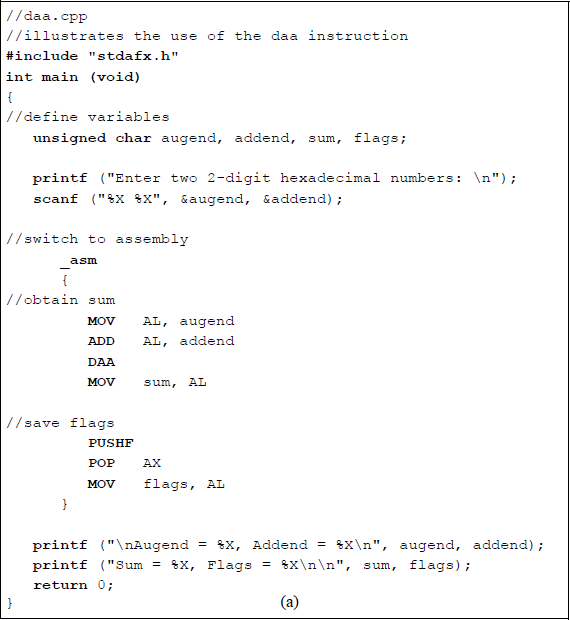
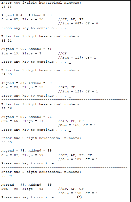
Program to illustrate the use of the DAA instruction: (a) the program and (b) the outputs.
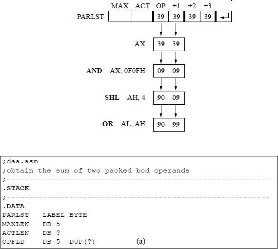
A similar program is shown in Figure 10.7, this time using only assembly language. The numbers that are entered from the keyboard are stored in the OPFLD input buffer as hexadecimal ASCII characters. If only the numbers 0 through 9 were entered, then only the hexadecimal characters 30 through 39 could be used.
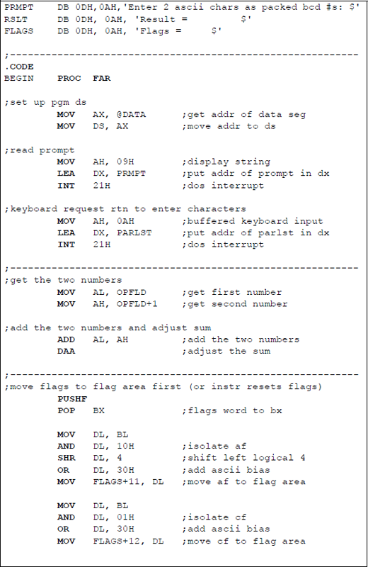
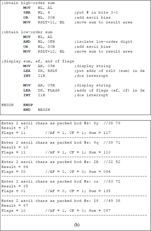
Assembly language program to illustrate using the DAA instruction: (a) the program and (b) the outputs.
In order to obtain higher-valued hexadecimal numbers as valid packed BCD numbers, the ASCII characters @ through Y and ‘through y can be entered. This yields @ = 40 through Y = 59 and ‘= 60 through y = 79. Thus, 8y yields 38 79 and 9q yields 37 91. The only drawback with this method is that the higher-valued numbers 80 through 89 and 90 through 99 cannot be realized. This presents no problem in illustrating the use of the DAA instruction.
If the higher-valued packed hexadecimal numbers are required, then a simple — but longer — procedure can be employed. Assume that it is required to use the DAA instruction to adjust the sum obtained by adding 99 + 99. The numbers are entered from the keyboard and stored in the OPFLD buffer, as shown below, where the first two digits are altered and changed to a valid packed BCD number. The second pair of digits are similarly altered.
10.3 ASCII Adjust AL after Subtraction (AAS) Instruction
The AAS instruction adjusts the result of a subtraction operation of two unpacked binary-coded decimal (BCD) operands. The resulting difference is converted to an unpacked BCD value and stored in general-purpose register AL, which is the implied source and destination for the AAS instruction.
This result may not be a valid BCD value. The AAS instruction converts the difference in register AL into a valid BCD number and stores the result in bits 3 through 0 of register AL and resets bits 7 through 4 of register AL. If the low-order four bits of the result in register AL are greater than nine or if the AF flag is set, then six is subtracted from AL and register AH is decremented by 1. In this case, both the auxiliary carry flag (AF) and the carry flag (CF) are set; otherwise, they are reset. The following flags are undefined: OF, SF, ZF, and PF.
When used in a program, the AAS instruction is preceded by a subtract (SUB) instruction or an integer subtraction with borrow (SBB) instruction. Shown below are two examples of subtraction in which the results are a valid and an invalid BCD number before using the AAS instruction.
AX = 00 08 – 00 03: AL = 05; AF = 0, CF = 0
AAS AL = 05H; AH = 00H
-------------------------------------------------------------------
AX = 00 06 – 00 08: AL = –2 (0FEH)
AL & 0FH = 0EH > 9; AF = 1, CF = 1
AAS AL – 6 = –8 (0F8H)
AL & 0FH = 08; AH = FFH
Figure 10.8 shows an assembly language module embedded in a C program that illustrates using the AAS instruction to adjust the result of subtracting two single-digit numbers. The numbers used in the preceding examples are entered from the keyboard for comparison.
10.4 Decimal Adjust AL after Subtraction (DAS) Instruction
The DAS instruction adjusts the result of a subtraction of two packed BCD operands. The instruction generates a valid packed BCD result and stores the difference in general-purpose register AL, which is the implied source and destination operand. The DAS instruction is preceded by a subtract (SUB) instruction or by an integer subtraction with borrow (SBB) instruction.
There are two rules that are used when subtracting packed BCD numbers regarding the resulting difference.
Rule 1: If the low-order four bits of the difference are greater than nine or if the auxiliary carry flag (AF) is set, then 06H is subtracted from the difference — which is contained in register AL — and the AF flag is set; otherwise, the AF flag is reset.
Rule 2: If the difference in AL is greater than 9FH or if the carry flag (CF) is set, then 60H is subtracted from AL and the CF flag is set; otherwise, the CF flag is reset.
For both rules, the overflow flag (OF) is undefined. Examples of subtracting packed BCD numbers are shown in Figure 10.9 for the following operands:
42 − 23 |
78 − 94 |
34 − 89. |
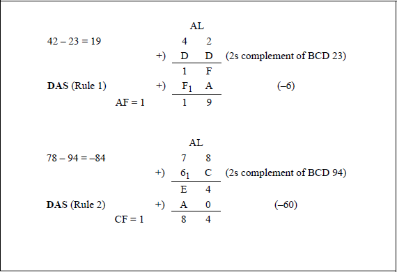
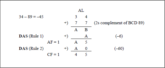
Figure 10.10 shows an assembly language module embedded in a C program that illustrates the application of the DAS instruction. Two valid packed BCD operands are entered from the keyboard and subtracted using the SUB instruction, then the difference is adjusted using the DAS instruction. The difference after the SUB instruction is displayed together with the result after the DAS instruction is executed. The low-order byte of the EFLAGS register is also displayed. The first three sets of operands are the same as the operands shown in the examples of Figure 10.9.
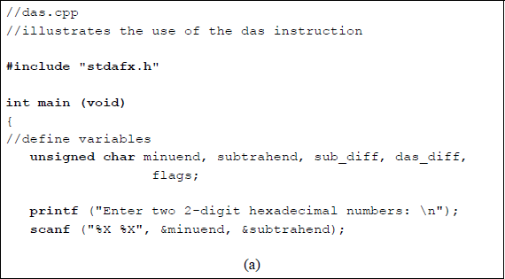
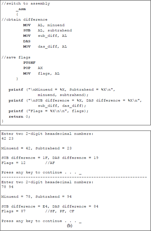
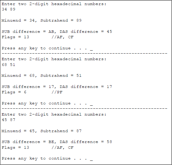
Program to illustrate the application of the DAS instruction: (a) the program and (b) the outputs.
10.5 ASCII Adjust AX after Multiplication (AAM) Instruction
The AAM instruction adjusts the product in general-purpose register AX resulting from multiplying two valid unpacked BCD operands. The adjustment creates a product of two unpacked BCD values in register AX: the high-order digit is in AH, the low-order digit is in AL. Register AX is the implied source and destination operand for the AAM instruction. The AAM instruction is preceded by a MUL instruction. The affected flags are the sign flag (SF), the zero flag (ZF), and the parity flag (PF), which are set according to the result in register AL. The overflow flag (OF), the auxiliary carry flag (AF), and the carry flag (CF) are undefined.
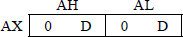
The AAM instruction divides register AL by 1010 (0AH) and stores the quotient in register AH and the remainder in register AL, as shown below. Since single digits have a maximum value of 9, the product has a maximum value of 8110 (51H); therefore, only register AL can contain an invalid BCD digit. Figure 10.11 depicts the sequence of operations performed by the MUL and AAM instructions.
AH ← AL/0AH (Quotient)
AL ← AL%0AH (Remainder, % is modulo)
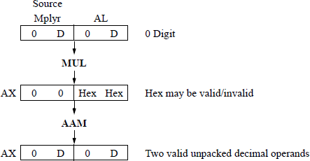
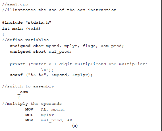
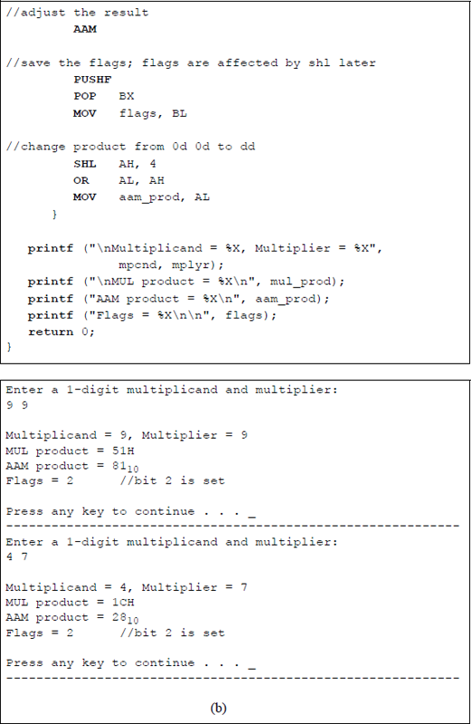
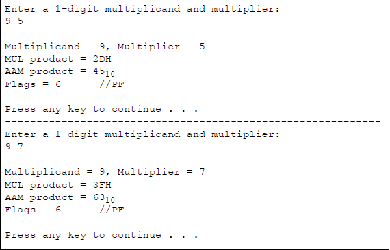
Figure 10.12 shows an assembly language module embedded in a C program that illustrates the use of the AAM instruction when preceded by a MUL instruction. In this program, the product in register AX is in the same format as shown in Figure 10.11; that is, two unpacked BCD digits. A one-digit multiplicand and a one-digit multiplier are entered from the keyboard. The resulting product is displayed as a hexadecimal value after the MUL instruction is executed and is displayed as two unpacked BCD digits after the AAM instruction is executed. The flags are also displayed.
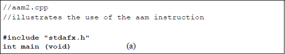
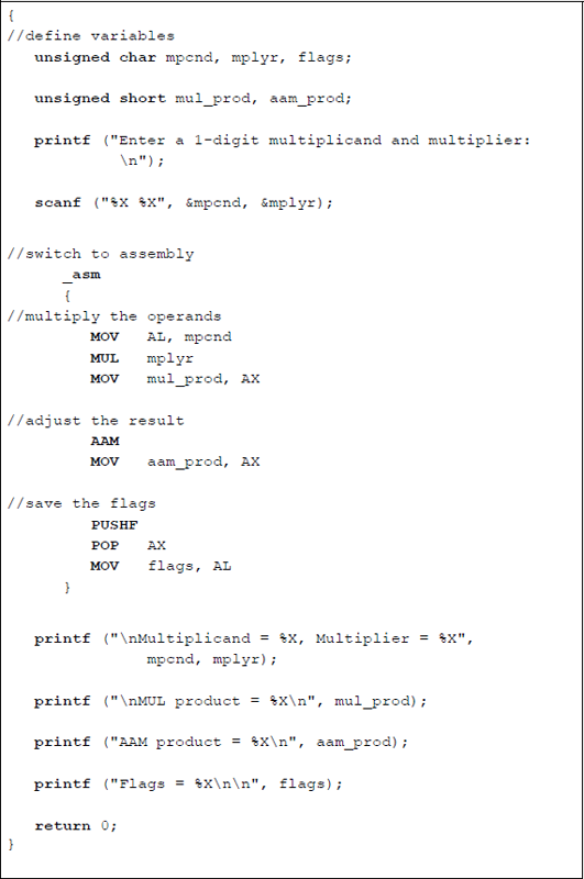
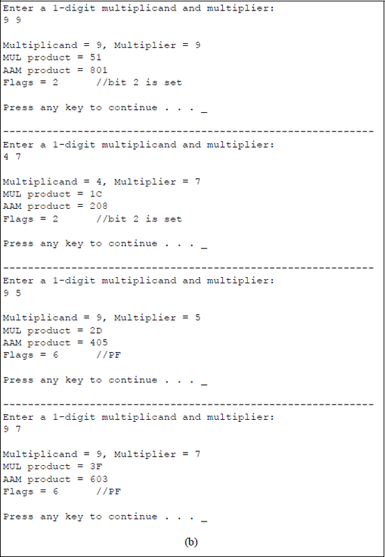
Program to illustrate the use of the AAM instruction: (a) the program and (b) the outputs.
Figure 10.13 shows an assembly language module embedded in a C program that also illustrates the application of the AAM instruction in conjunction with the MUL instruction. This program demonstrates a slightly different version of the same application using the MUL instruction and the AAM instruction that was shown in Figure 10.12; this time the product is displayed as a packed BCD value.
Program to illustrate the use of the AAM instruction to obtain a packed BCD product: (a) the program and (b) the outputs.
The unpacked product is shown below in register AX, where D represents a BCD digit. In order to obtain a packed format in register AL, the unpacked digit in register AH is shifted left logically (SHL) four bit positions. Then register AH is ORed with register AL to obtain the requisite two-digit packed format.
A one-digit multiplicand and a one-digit multiplier are entered from the keyboard; the resulting product is displayed after the MUL instruction is executed and after the AAM instruction is executed. Although the flags are not usually required, they are also displayed. A program to multiply a multidigit multiplicand by a single-digit multiplier is left as a problem.
Figure 10.14 shows an assembly language program — not embedded in a C program — that uses the MUL instruction in conjunction with the AAM instruction to calculate the area of a triangle, as shown below.
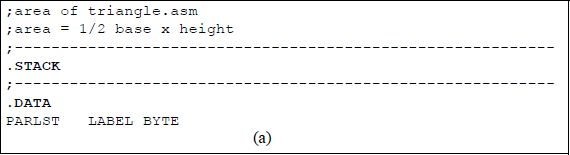
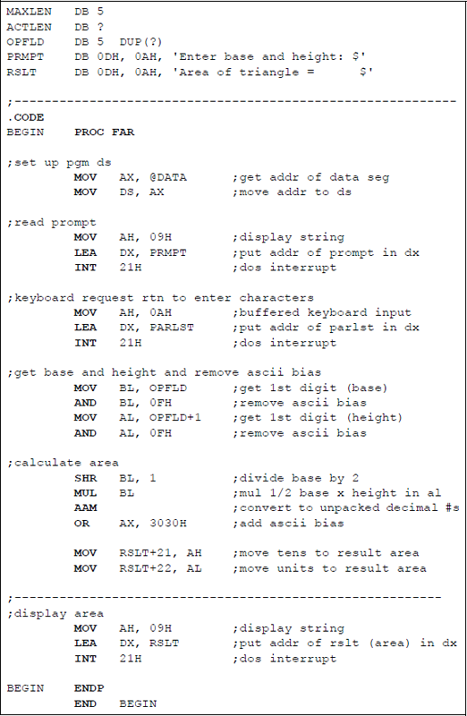
Calculate the area of a triangle using the MUL and AAM instructions: (a) the program and (b) the outputs.
A single-digit base and a single-digit height are entered from the keyboard and stored in the OPFLD input buffer of the parameter list (PARLST). Since the parameters are entered as ASCII characters, they must first be unpacked — ASCII bias removed — before they are used. If the base value is an odd number, then the base is truncated — rounded down — when it is divided by 2.
10.6 ASCII Adjust AX before Division (AAD) Instruction
The AAD instruction converts two unpacked digits in register AX — high-order digit in register AH and low-order digit in register AL — to an equivalent binary value, stores the result in register AL, and resets register AH. The AAD instruction normally precedes a DIV instruction, but can be used independently to convert two unpacked BCD digits in register AX to an equivalent radix 10 value in registers AH and AL, where AH = 00H.
When the value in register AX is then divided by an unpacked BCD value, the unpacked quotient is stored in register AL and the unpacked remainder is stored in register AH. The AAD instruction multiplies register AH by 1010 (0AH), then adds the product to the contents of register AL, and stores the result in register AL, as shown below.
AL ← (AH × 0AH) + AL
AH ← 00H
The affected flags are the sign flag (SF), the zero flag (ZF), and the parity flag (PF), which are set or reset according to the result in register AL. The overflow flag (OF), the auxiliary carry flag (AF), and the carry flag (CF) are unaffected.
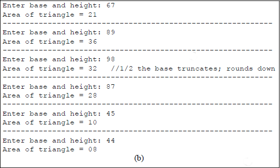
An example is shown in Figure 10.15 that divides AX = 08 04H by BL = 09H using the AAD instruction and the DIV instruction. The AAD instruction changes AX from AX = 08 04H to AX = 00 8410 (00 54H), then the DIV instruction produces the result in AX as AH = 03 (remainder), AL = 09 (quotient).
Figure 10.16 shows an assembly language program — not embedded in a C program — that uses the AAD instruction in conjunction with the DIV instruction to divide a 2-digit unpacked BCD dividend by a 1-digit unpacked BCD divisor. The divide operation is executed with several different operands that are entered from the keyboard.
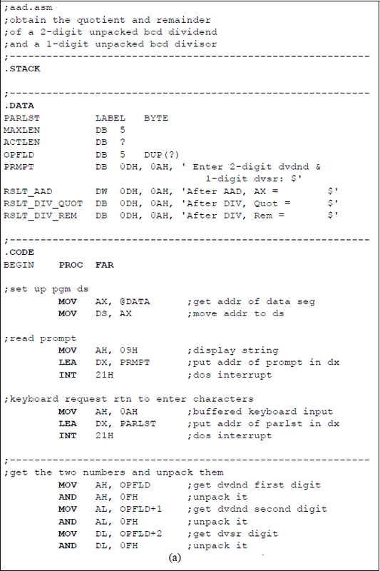
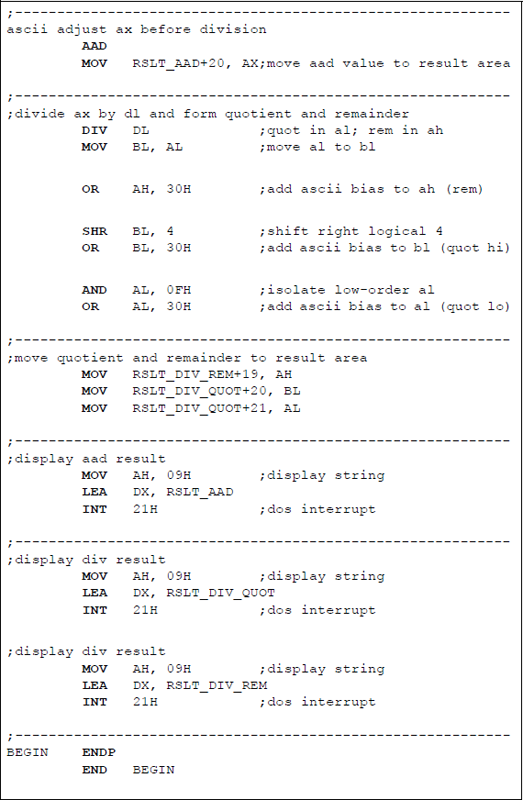
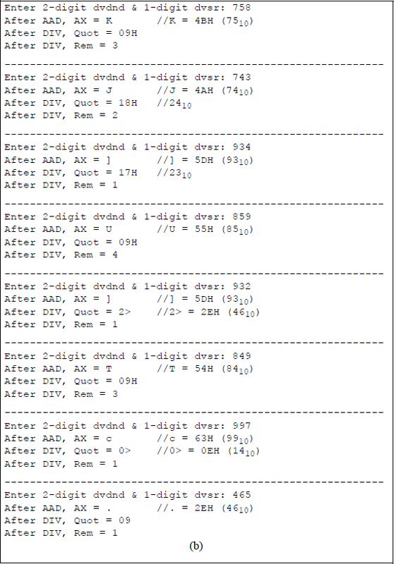
Assembly language program to illustrate using the AAD instruction in conjunction with the DIV instruction: (a) the program and (b) the outputs.
The results of the AAD instruction are displayed together with the quotient and remainder obtained from the DIV instruction. The results obtained from executing the AAD instruction and the DIV instruction may not necessarily be displayed as numerical ASCII digits — 30 (0) through 39 (9). The ASCII digits can range from 21H (!) to 7EH (~) depending on the results. For example, dividing a dividend of 74 by a divisor of 3 yields a quotient of 24 and a remainder of 2. Executing the AAD instruction for these operands displays a value of J (4AH = 74); executing the DIV instruction displays a quotient of 18H (24), and a remainder of 2H (2).
10.7 Problems
10.1 Show the contents of register AX and the values of the indicated flags after the ADD instruction has been executed and after the AAA instruction has been executed.
ADD AL, CHAAABefore
After ADD
After AAA
(a)
AX = 00 04H
AX =
AX =
CH = 07H
AF =
AF = , CF =
(b)
AX = 05 05H
AX =
AX =
CH = 07H
AF =
AF = , CF =
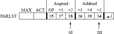
10.2 Write an assembly language program — not embedded in a C program — that adds two ASCII numbers that are entered from the keyboard, where the ASCII numbers have three digits each. The first number entered is the augend; the second number entered is the addend. The parameter list (PARLST) format is shown below for convenience. The ASCII numbers shown in the PARLST yield a sum of 127210. Enter at least four sets of numbers and display the resulting sums.
- 10.3 Let register AX = 05 35H and register BL = 39H. After executing the instructions shown below, determine the contents of AX and the auxiliary carry flag (AF).
ADD |
AL, BL |
AAA |
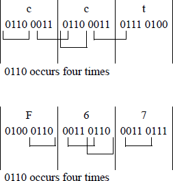
10.4 Write an assembly language program — not embedded in a C program — for a sequence detector that detects the number of times that the four-bit sequence 0110 appears anywhere in the keyboard input buffer (OPFLD) when three ASCII characters are entered. This program does not necessarily require BCD instructions.
The bit sequence 0110 may be in the high-order four bits of the keyboard character, the low-order four bits, both high-order and low-order four bits, across the boundary of the high- and low-order bits, or across the boundary of two contiguous bytes. Display the number of times that the sequence occurs. A flowchart may make the program easier to code. Two examples of input data are shown below for cct and F67.
10.5 In each part below, assume that the following instructions are executed:
ADD AL, BLDAA(a) Give the values of AL after the ADD instruction has been executed, but before the DAA instruction has been executed for the indicated register values shown below.
(b) Give the values of AL, the carry flag (CF), and the auxiliary carry flag (AF) after the DAA instruction has been executed for the indicated register values shown below.
(1) AL = 35H, BL = 48H
(2) AL = 47H, BL = 61H
(3) AL = 75H, BL = 46H
Then write an assembly language module embedded in a C program to verify the results.
10.6 Given the two instructions shown below, determine the ADD sum, the DAA sum, the auxiliary carry flag (AF), the parity flag (PF), and the carry flag (CF) after the instructions have been executed when AL = 89H and BL = 64H.
ADD AL, BLDAA10.7 Write an assembly language module embedded in a C program that adds two 4-digit hexadecimal numbers. Display the carry flag (CF) and the sum for several different numbers.
10.8 Perform a subtraction and adjustment of the following two operands: 07 – 09. Show the details of the subtraction and adjustment.
10.9 Design an assembly language program — not embedded in a C program — to perform the following subtraction using the AAS instruction: 76 – 48, then display the result.
10.10 Design an assembly language module embedded in a C program to perform subtraction on two unpacked BCD operands using the AAS instruction, then display the result. Enter several different operands.
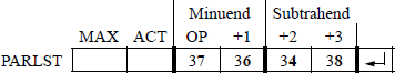
10.11 Design an assembly language program — not embedded in a C program — that performs subtraction on two unpacked BCD operands using the AAS instruction. Display the results of several different operands. The first two operands are shown below as: 76 (37 36) and 48 (34 38).
10.12 Let AL = 00H and BL = 61H. Execute the following two instructions and then show the contents of AL, CF, and AF after the SUB instruction has been executed and after the DAS instruction has been executed:
SUB AL, BLDAS10.13 Write an assembly language module embedded in a C program that uses the DAS instruction to subtract and adjust two 4-digit hexadecimal numbers. Display the difference and the resulting flags.
10.14 Write an assembly language program — not embedded in a C program — that performs subtraction on two valid packed BCD operands using the DAS instruction. Display the results of several different operands.
10.15 Show the contents of register AX after the MUL instruction has been executed and after the AAM instruction has been executed for AL = 04H, BL = 06H and AL = 05H, BL = 07H.
MUL BLAAM10.16 Write an assembly language program — not embedded in a C program — that obtains the product of two unpacked single-digit ASCII (BCD) numbers using the MUL and AAM instructions. Display the multiplicand, the multiplier, and the product.
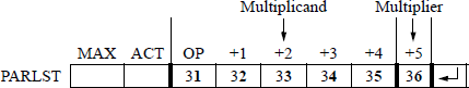
10.17 Write an assembly language program — not embedded in a C program — that multiplies a five-digit multiplicand by a one-digit multiplier using the MUL instruction in combination with the AAM instruction. The ADD instruction and the AAA instruction will also be used in implementing the program.
The five-digit multiplicand and the one-digit multiplier are entered from the keyboard and stored in the OPFLD, as shown below using a multiplicand of 12345 and a multiplier of 6. Enter several different multiplicands and multipliers, then display the operands and the resulting product.
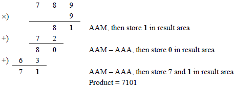
The paper-and-pencil example shown below may help to illustrate the algorithm used in the program.
10.18 Write an assembly language program — not embedded in a C program — that calculates the number of hours, minutes, and seconds from a number of seconds that are entered from the keyboard. The number of seconds entered ranges from 10,000 to 60,000. Enter several different 5-digit numbers of seconds. Do not use the LOOP instruction in this program — Problem 10.20 will use the LOOP instruction to reduce the amount of code. This program will use the AAM instruction.
10.19 Repeat Problem 10.18, this time using an assembly language module embedded in a C program. Note the simplicity of this program. There is no requirement to remove the ASCII bias for the numbers that are entered from the keyboard, or to restore the ASCII bias before displaying the hours, minutes, and seconds. It is also not necessary to establish stack or data segments. The range is the same: 10,000 to 60,000 seconds.
10.20 Write an assembly language program to repeat Problem 10.18 — not embedded in a C program — that calculates the number of hours, minutes, and seconds from a number of seconds that are entered from the keyboard. This time use a loop to calculate the sum that is represented by the digits that are entered from the keyboard. The number of seconds entered ranges from 10,000 to 60,000. Enter several different 5-digit numbers of seconds. This program will use the MUL, DIV, and AAM instructions.
10.21 Use the AAD instruction in conjunction with the DIV instruction to divide register AX = 06 04H by register BL = 05H. Show the result of the AAD instruction and the quotient and remainder obtained from the DIV instruction.
10.22 Use the AAD instruction in conjunction with the DIV instruction to divide register AX = 05 09H by register BL = 03H. Show the result of the AAD instruction and the quotient and remainder obtained from the DIV instruction.
10.23 The AAD instruction can be used independently of the DIV instruction for certain applications, as used in the program for this problem. Create a flowchart that demonstrates a method to display one of the twelve months of a calendar from a number that is entered from the keyboard. For example, the number 09 will display the month of September. Then write an assembly language program — not embedded in a C program — that performs this function.
The months are listed in the data segment and each month contains nine letters to correspond to the month with the most letters — September. Enter several month numbers from the keyboard. Other arithmetic instructions will be used in this program in conjunction with the AAD instruction.