Table of Contents for
X86 Assembly Language and C Fundamentals
 X86 Assembly Language and C Fundamentals
Published by
CRC Press, 2015
X86 Assembly Language and C Fundamentals
Published by
CRC Press, 2015
- X86 Assembly Language and C Fundamentals
- Preliminaries
- By the same Author
- X86 Assembly Language and C Fundamentals
- X86 Assembly Language and C Fundamentals
- Preface
- Chapter 1 Number Systems and Number Representations
- Chapter 2 X86 Processor Architecture
- Chapter 3 Addressing Modes
- Chapter 4 C Programming Fundamentals
- Chapter 5 Data Transfer Instructions
- Chapter 6 Branching and Looping Instructions
- Chapter 7 Stack Operations
- Chapter 8 Logical, Bit, Shift, and Rotate Instructions
- Chapter 9 Fixed-Point Arithmetic Instructions
- Chapter 10 Binary-Coded Decimal Arithmetic Instructions
- Chapter 11 Floating-Point Arithmetic Instructions
- Chapter 12 Procedures
- Chapter 13 String Instructions
- Chapter 14 Arrays
- Chapter 15 Macros
- Chapter 16 Interrupts and Input/Output Operations
- Chapter 17 Additional Programming Examples
- Appendix A ASCII Character Codes
- Appendix B Answers to Select Problems
Chapter 11
Floating-Point Arithmetic Instructions
The fixed-point number representation is appropriate for representing numbers with small numerical values that are considered as positive or negative integers; that is, the implied radix point is to the right of the low-order bit. The same algorithms for arithmetic operations can be employed if the implied radix point is to the immediate right of the sign bit, thus representing a signed fraction.
The range for a 16-bit fixed-point number is from (–215) to (+215 – 1), which is inadequate for some numbers; for example, the following operation:
This operation can also be written in scientific notation, as follows:
where 10 is the base and 11 and –7 are the exponents. Floating-point notation is equivalent to scientific notation in which the radix point (or binary point) can be made to float around the fraction by changing the value of the exponent; thus, the term floating point. In contrast, fixed-point numbers have the radix point located in a fixed position, usually to the immediate right of the low-order bit position, indicating an integer.
The base and exponent are called the scaling factor, which specify the position of the radix point relative to the significand digits (or fraction digits). Common bases are 2 for binary, 10 for decimal, and 16 for hexadecimal. The base in the scaling factor does not have to be explicitly specified in the floating-point number.
11.1 Floating-Point Fundamentals
Floating-point numbers consist of the following three fields: a sign bit, s; an exponent, e; and a fraction, f. These parts represent a number that is obtained by multiplying the fraction, f , by a radix, r, raised to the power of the exponent, e, as shown in Equation 11.1 for the number A, where f and e are signed fixed-point numbers, and r is the radix (or base).
The exponent is also referred to as the characteristic; the fraction is also referred to as the significand or mantissa. Although the fraction can be represented in sign-magnitude, diminished-radix complement, or radix complement, the fraction is predominantly expressed in sign-magnitude representation — sign bit plus fraction.
If the fraction is shifted left k bits, then the exponent is decremented by an amount equal to k ; similarly, if the fraction is shifted right k bits, then the exponent is incremented by an amount equal to k. Consider an example in the radix 10 floating-point representation. Let . This number can be rewritten as or , both with an implied base of 10.
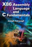
Figure 11.1 shows the format for 32-bit single-precision and 64-bit double-precision floating-point numbers. The single-precision format consists of a sign bit that indicates the sign of the number, an 8-bit signed exponent, and a 23-bit unsigned fraction. The double-precision format consists of a sign bit, an 11-bit signed exponent, and a 52-bit unsigned fraction.
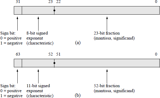
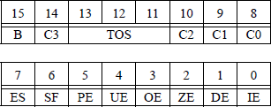
Figure 11.2(a) shows the eight data registers — called the register stack — used in the floating-point unit (X87 FPU). The stack top ST(0) — also referred to as ST — is register R0 and, like a normal stack, builds toward lower-numbered registers. The register immediately below the stack top is referred to as ST(1); the register immediately below ST(1) is referred to as ST(2), and so forth. When the stack is full, that is, the registers at ST(0) through the register at ST(7) contain valid data, a stack wraparound occurs if an attempt is made to store additional data on the stack. This results in a stack overflow because the unsaved data is overwritten. The stack registers are specified by three bits — 000 through 111 — to reference ST(0) through ST(7). Therefore, ST(i) references the ith register from the current stack top.
Double extended-precision register stack and tag register for the floating-point unit: (a) the register stack and (b) the tag register.
The 16-bit tag register contains a 2-bit tag field for each register that specifies the type of data contained in the corresponding register, as shown in Figure 11.2(b). The values signify whether the data is valid (00); zero (01); a special floating-point number, such as not-a-number (NaN), a value of infinity, a denormal number, or unsupported format (10); or an empty register (11).
When adding or subtracting floating-point numbers, the exponents are compared and made equal resulting in a right shift of the fraction with the smaller exponent. The comparison is easier if the exponents are unsigned — a simple comparator can be used for the comparison. As the exponents are being formed, a bias constant is added to the exponents such that all exponents are positive internally.
For the single-precision format, the bias constant is +127 — also called excess-127; therefore, the biased exponent has a range of
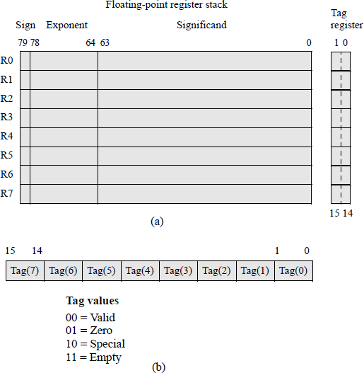
Fractions in the IEEE format are normalized; that is, the leftmost significant bit is a 1. Figure 11.3 shows unnormalized and normalized numbers in the 32-bit format. Since there will always be a 1 to the immediate right of the radix point, the 1 bit is not explicitly shown — it is an implied 1.
The bias constant has a value that is equal to the most positive exponent. For example, if the exponents are represented by n bits, then the bias is 2n − 1 – 1. For n = 4, the most positive number is 0111 (+7). Therefore, all biased exponents are of the form shown in Equation 11.2. The advantage of using biased exponents is that they are easier to compare without having to consider the signs of the exponents. The main reason for biasing is to determine the correct alignment of the fractions by aligning the radix points, and to determine the number of bits to shift a fraction in order to obtain proper alignment.
11.1.1 Rounding Methods
Rounding deletes one or more low-order bits of the significand and adjusts the retained bits according to a particular rounding technique. The reason for rounding is to reduce the number of bits in the result in order to conform to the size of the significand; that is, in order to be retained within the word size of the machine. Since bits are deleted, this limits the precision of the result.
In some floating-point operations, the result may exceed the number of bits of the significand. For example, rounding can occur when adding two n-bit numbers that result in a sum of n + 1 bits. The overflow is handled by shifting the fraction right 1 bit position, resulting in the low-order bit being lost unless it is saved. Rounding attempts to dispose of the extra bits and yet preserve a high degree of accuracy. This section presents three common techniques for rounding that still maintain a high degree of accuracy.
Truncation rounding This method of rounding is also called chopping. Truncation deletes extra bits and makes no changes to the retained bits. Aligning fractions during addition or subtraction could result is losing several low-order bits, so there is obviously an error associated with truncation. Assume that the following fraction is to be truncated to four bits:
Then all fractions in the range to will be truncated to . The error ranges from 0 to 0.00001111. In general, the error ranges from 0 to approximately 1 in the low-order position of the retained bits.
Truncation is a fast and easy method for deleting bits resulting from a fraction underflow and requires no additional hardware. There is one disadvantage in that a significant error may result. A fraction underflow can occur when aligning fractions during addition or subtraction when one of the fractions is shifted to the right. Truncation does not round up or round down, but simply deletes a specified number of the low-order significand bits.
Adder-based rounding The result of a floating-point arithmetic operation can be rounded to the nearest number that contains n bits. This method is called adder-based rounding and rounds the result to the nearest approximation that contains n bits. The operation is as follows: The bits to be deleted are truncated and a 1 is added to the retained bits if the high-order bit of the deleted bits is a 1. When a 1 is added to the retained bits, the carry is propagated to the higher-order bits. If the addition results in a carry-out of the high-order bit position, then the fraction is shifted right one bit position and the exponent is incremented.
Consider the fraction — where the xs are 0s or 1s — which is to be truncated and rounded to four bits. Using adder-based rounding, this rounds to and the resulting fraction is where is a 1 or 0. Examples of adder-based rounding are shown in Figure 11.4 in which the fractions are to be rounded to four bits.
In Figure 11.4(a), the part of the fraction to be deleted for rounding has a value that is greater than or equal to half its maximum value of 15. Therefore, a 1 is added to the retained bits, which results in the true value being approached from above. That is, the part being deleted has a maximum value of 1111 (15), while its actual value is 1000 (8). Since a value of 8 ≥ 7.5, a 1 is added to the retained bits. A similar reasoning is used for Figure 11.4(b); however, the actual value of the part to be deleted is 0111 (7). Since 7 < 7.5, the low-order four bits are deleted and a 1 is not added to the retained bits, which results in the true value being approached from below.
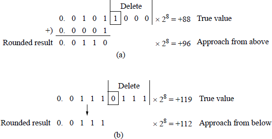
Adder-based rounding examples: (a) a 1 is added to the retained bits and (b) no rounding occurs.
Adder-based rounding is an unbiased method that generates the nearest approximation to the number being rounded. Although adder-based rounding is obviously a better method of rounding than truncation, additional hardware is required to accommodate the addition cycle, thus adding more delay to the rounding operation.
von Neumann rounding The von Neumann rounding method is also referred to as jamming and is similar to truncation. If the bits to be deleted are all zeroes, then the bits are truncated and there is no change to the retained bits. However, if the bits to be deleted are not all zeroes, then the bits are deleted and the low-order bit of the retained bits is set to 1. Thus, when 8-bit fractions are rounded to four bits, fractions in the range
will all be rounded to
Therefore, the error ranges from approximately –1 to +1 in the low-order bit of the retained bits when
and when
Although the error range is larger in von Neumann rounding than with truncation rounding, the individual errors are evenly distributed over the error range. Thus, positive errors will be inclined to offset negative errors for long sequences of floatingpoint calculations involving rounding. The von Neumann rounding method has the same total bias as adder-based rounding; however, it requires no more time than truncation.
There are over 90 floating-point instructions in the X86 instruction set; therefore, only the most commonly used instructions will be presented in detail. The predominant prefix for the floating-point mnemonics is the letter F. The following types of floating-point instructions will be presented: load data instructions, store data instructions, addition instructions, subtraction instructions, multiplication instructions, division instructions, compare instructions, trigonometric instructions, and a select variety of additional instructions.
11.2 Load Data Instructions
This section describes the floating-point instructions that push different types of data onto the register stack. These are classified as data transfer instructions and include the load floating-point value (FLD) instruction, several load constant instructions, such as FLD1, FLDL2T, FLDL2E, FLDPI, FLDLG2, FLDLN2, and FLDZ (all of which will be described in later sections), the load X87 FPU control word (FLDCW) instruction, and the load X87 FPU environment (FLDENV) instruction. Also included is the load integer (FILD) and the load binary-coded decimal (FBLD) instructions.
11.2.1 Load Floating-Point Value (FLD) Instruction
The FLD instruction pushes the contents of the X87 source operand onto the register stack. The source operand can be any of the three floating-point data type formats: single precision, double precision, or double extended precision. Single-precision formats and double-precision formats are automatically converted to the double extended-precision format. The syntax for the FLD instruction is shown below, where FLD ST(i) is a register in the register stack.
FLD m32/64/80fp (memory, 32-, 64-, or 80-bit floating-point)
FLD ST(i)
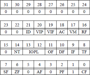
If a stack overflow or a stack underflow results from a floating-point operation, the stack fault flag (SF) — bit 6 of the status word reproduced in Figure 11.5 — is set. When the SF flag is set, the condition code flag C1 (bit 9) is examined. If C1 = 1, a stack overflow has occurred; if C1 = 0, a stack underflow has occurred.
A simplified register stack is shown in Figure 11.6. Assume that memory contains the following floating-point values:
flp1 = 25.0
flp2 = 10.0
flp3 = 15.0
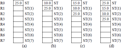
Assume also that the instructions shown below are executed sequentially. The stack will contain the values shown in Figure 11.6 after the instructions have been executed. The fourth instruction will push the contents of ST(2) onto the stack; however, the contents of location ST(2) will not change.
FLD flp1 Figure 11.6(a)
FLD flp2 Figure 11.6(b)
FLD flp3 Figure 11.6(c)
FLD ST(2) Figure 11.6(d)
The floating-point instructions can access only the X87 registers, not the X86 general-purpose registers. Data must be transmitted between processors via memory. All addressing of the register stack is relative to the current top of stack (TOS), which is contained in bits 13 through 11 of the X87 status word. Like a regular stack, a load operation decrements the TOS by one and stores the new data in the new TOS register; this is similar to a PUSH operation. A store operation sends the data that resides in the current TOS register to the destination, then increments the TOS by one; this is similar to a POP operation.
11.2.2 Load Constant Instructions
There are seven load constant instructions that push specific values onto the register stack as double extended-precision floating-point values. These are listed below.
FLD1 instruction This instruction pushes +1.0 onto the register stack.
FLDL2T instruction This instruction pushes log210 onto the register stack, where log210 represents the exponent to which the base 2 must be raised to yield 10. The general equation is
where b is the base. Thus,
FLDL2E instruction This instruction pushes log2e onto the register stack, where log2e represents the exponent to which the base 2 must be raised to yield e, where
The notation for the constant e was selected by the mathematician Leonhard Euler because it was the first letter of the word exponential. The general equation is
where b is the base. Thus,
FLDPI instruction This instruction pushes π onto the register stack, where π is approximately 3.14159.
FLDLG2 instruction This instruction pushes log102 onto the register stack, where log102 represents the exponent to which the base 10 must be raised to yield 2. The general equation is
where b is the base. Thus,
FLDLN2 instruction This instruction pushes loge2 onto the register stack, where loge2 represents the exponent to which the base e must be raised to yield 2 and
The general equation is
where b is the base. Thus,
FLDZ instruction This pushes +0.0 onto the register stack.
11.2.3 Load X87 FPU Control Word (FLDCW) Instruction
This instruction loads a 16-bit source operand from memory into the floating-point unit control word register, which is reproduced in Figure 11.7.
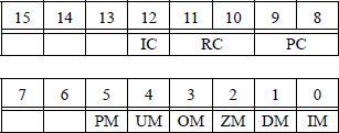
The syntax for the FLDCW instruction is shown below, where m2byte specifies a 2-byte memory location. This instruction is used to load a new control word from memory in order to modify the existing control word — thus changing the mode of operation of the floating-point unit — or to establish a new control word.
FLDCW m2byte (memory, 2 bytes)
11.2.4 Load X87 FPU Environment (FLDENV) Instruction
The FLDENV instruction loads the operating environment into the floating-point registers from memory as 14-byte data or as 28-byte data. The operating environment is loaded into the following registers: control word, status word, tag word, instruction pointer (IP) offset, data pointer offset, and last opcode pointer. The information that is loaded depends on the operating mode of the floating-point unit — protected mode or real mode — and the current operand size attribute, either 16 bits or 32 bits. The syntax for the FLDENV instruction is shown below, where m14/28byte specifies a memory operand of 14 bytes or 28 bytes.
FLDENV m14/28byte (memory, 14 or 28 bytes)
The FLDENV instruction should use the identical operating mode — protected mode or real mode — as was used with the store X87 FPU environment (FSTENV) instruction, which is covered in the next section.
11.2.5 Load Integer (FILD) Instruction
The FILD instruction changes a signed integer source operand in memory to a double extended-precision floating-point number and pushes that value onto the register stack. The format for the integer source operand can be a word, a doubleword, or a quadword. The syntax for the FILD instruction is shown below.
FILD m16int (memory, 16-bit integer)
FILD m32int (memory, 32-bit integer)
FILD m64int (memory, 64-bit integer)
11.2.6 Load Binary-Coded Decimal (FBLD) Instruction
The FBLD instruction converts a signed 80-bit packed binary-coded decimal (BCD) source operand in memory to a double extended-precision floating-point number and pushes that value onto the register stack. The instruction does not check for invalid digits. The syntax for the FBLD instruction is shown below.
FBLD m80dec (memory, 80 bits decimal)
11.3 Store Data Instructions
This section describes the floating-point instructions that store — or store and pop — different types of data on the register stack and other specific registers. These instructions include the store bcd integer and pop (FBSTP) instruction, the store integer (FIST) instruction, the store integer and pop (FISTP) instruction, the store integer with truncation (FISTTP) instruction, the store floating-point value (FST) instruction, the store floating-point value and pop (FSTP) instruction, the store X87 FPU control word (FSTCW) instruction, the store X87 FPU environment (FSTENV) instruction, and the store X87 FPU status word (FSTSW).
11.3.1 Store BCD Integer and Pop (FBSTP) Instruction
The FBSTP instruction converts the value in ST(0) of the register stack to a BCD integer and stores the result in the destination operand located in a 10-byte area in memory. If the stored value is not an integer, then the operand is rounded to an integer using the rounding method specified by bits 11 and 10 of the RC field in the floating-point control word register of Figure 11.7. The register stack is then popped. A pop operation marks the ST(0) register as empty and increments the stack pointer by 1 — bits 13 through 11 (TOS or TOP) of the X87 floating-point status word, as shown in Figure 11.5. The syntax for the FBSTP instruction is shown below, where m80bcd is the destination operand of 80 bits in the BCD format.
FBSTP m80bcd (memory, 80 bits)
11.3.2 Store Integer (FIST) Instruction
The FIST instruction converts the value in ST(0) of the register stack to a signed integer — rounded if necessary — and stores the result in the destination memory location as a word or doubleword. The syntax for the FIST instruction is shown below, where the destination operand is either a 16-bit integer or a 32-bit integer.
FIST m16int (memory, 16-bit integer)
FIST m32int (memory, 32-bit integer)
11.3.3 Store Integer and Pop (FISTP) Instruction
The FISTP instruction operates identically to the FIST instruction and then pops the register stack. It stores the value in ST(0) into memory as a word, doubleword, or quadword integer. The syntax for the FISTP instruction is shown below, where the destination operand is either a 16-bit integer, a 32-bit integer, or a 64-bit integer.
FISTP m16int (memory, 16-bit integer)
FISTP m32int (memory, 32-bit integer)
FISTP m64int (memory, 64-bit integer)
11.3.4 Store Integer with Truncation and Pop (FISTTP) Instruction
The FISTTP instruction converts the operand in ST(0) to a signed integer using the truncation rounding method, then stores the result in the destination location and pops the register stack. Truncation deletes extra bits and makes no changes to the retained bits. This method of rounding is also referred to as chopping. The syntax for the FISTTP instruction is shown below.
FISTTP m16int (memory, 16-bit integer)
FISTTP m32int (memory, 32-bit integer)
FISTTP m64int (memory, 64-bit integer)
Figure 11.8 shows an assembly language module embedded in a C program that illustrates the application of the FIST and the FISTTP instructions. Two floating-point numbers are entered from the keyboard and then used by the FIST and FISTTP instructions. The integer results are then displayed.
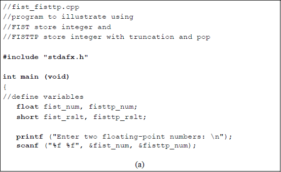
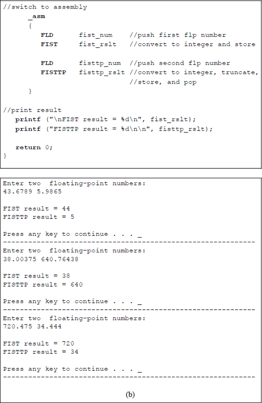
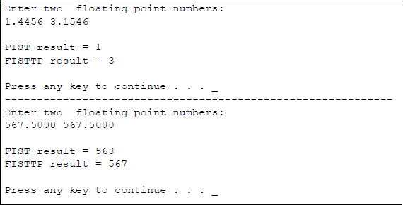
Program to illustrate using the FIST and the FISTTP instructions: (a) the program and (b) the outputs.
11.3.5 Store Floating-Point Value (FST) Instruction
The FST instruction stores the operand in ST(0) to the destination location, which can be a location in memory or another register in the register stack. If the destination is a memory location, then the operand is converted to the single-precision format or the double-precision format. The syntax for the FST instruction is shown below.
FST m32fp (memory, 32 bits floating-point)
FST m64fp (memory, 64 bits floating-point)
FST ST(i) (copy ST(0) to ST(i))
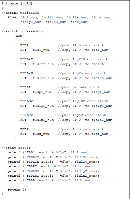
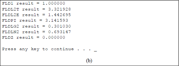
Figure 11.9 shows an assembly language module embedded in a C program that illustrates using the FST instruction in conjunction with the load constant instructions: FLD1, FLDL2T, FLDL2E, FLDPI, FLDLG2, FLDLN2, and FLDZ. The load constant instructions push the appropriate values onto the register stack; the FST instruction stores them in the assigned locations in memory, then the results are displayed.
11.3.6 Store Floating-Point Value and Pop (FSTP) Instruction
The FSTP instruction stores the operand in ST(0) to the destination location, which can be a location in memory or another register in the register stack, then pops the register stack. If the destination is a memory location, then the operand is converted to the single-precision format, the double-precision format, or the double extended-precision format. The syntax for the FSTP instruction is shown below.
FSTP m32fp (memory, 32 bits floating-point and pop stack)
FSTP m64fp (memory, 64 bits floating-point and pop stack)
FSTP m80fp (memory, 80 bits floating-point and pop stack)
FSTP ST(i) (copy ST(0) to ST(i) and pop stack)
11.3.7 Store X87 FPU Control Word (FSTCW) Instruction
The FSTCW instruction stores the floating-point control word at the memory location specified by the destination location. The FSTCW also resolves any pending unmasked floating-point exceptions before storing the control word. Refer to Section 11.2.3 for the control word format. The syntax for the FSTCW instruction is shown below. There is a second store X87 FPU control word (FNSTCW) that does not check for pending unmasked floating-point exceptions. The syntax for the FNSTCW is also shown below.
FSTCW m2byte (memory, two bytes check for exceptions)
FNSTCW m2byte (memory, two bytes do not check for exceptions)
11.3.8 Store X87 FPU Environment (FSTENV) Instruction
The FSTENV instruction saves the floating-point unit environment in a memory location as indicated by the destination operand. The operating environment consists of the following registers: control word, status word, tag word, instruction pointer (IP) offset, data pointer offset, and last opcode pointer. The format of the environment depends on the operating mode of the floating-point unit — protected mode or real mode — and the current operand size attribute, either 16 bits or 32 bits. The FSTENV instruction then masks all floating-point exceptions.
The syntax for the FSTENV instruction is shown below. There is a second store X87 FPU environment (FNSTENV) that does not check for pending unmasked floating-point exceptions. The syntax for the FNSTENV is also shown below.
FSTENV m14byte (memory, 14 bytes check for exceptions,
then mask exceptions)FSTENV m28byte (memory, 28 bytes check for exceptions,
then mask exceptions)FNSTENV m14byte (memory, 14 bytes do not check for
exceptions, then mask exceptions)FNSTENV m28byte (memory, 28 bytes do not check for
exceptions, then mask exceptions)
11.3.9 Store X87 FPU Status Word (FSTSW) Instruction
The FSTSW instruction stores the floating-point status word at the memory location specified by the destination location. The destination is a 2-byte memory location or the general-purpose register AX. The FSTSW also resolves any pending unmasked floating-point exceptions before storing the status word.
The syntax for the FSTSW instruction is shown below. There is a second store X87 FPU status word (FNSTSW) that does not check for pending unmasked floatingpoint exceptions. The syntax for the FNSTSW is also shown below.
FSTSW m2byte (memory, two bytes, check for exceptions)FSTSW AX (register AX, check for exceptions)FNSTSW m2byte (memory, two bytes,
do not check for exceptions)FNSTSW AX (register AX, do not check for exceptions)
11.4 Addition Instructions
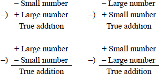
The addition of two fractions is identical to the addition algorithm presented in fixed-point addition. If the signs of the operands are the same (Asign ⊕ Bsign = 0), then this is referred to as true addition and the fractions are added. True addition corresponds to one of the following conditions:
Floating-point addition is defined as shown in Equation 11.3 for two numbers A and B, where and .
The terms and are shifting factors to shift the fraction with the smaller exponent. This is analogous to a divide operation, since r–(eA−eB) is equivalent to , which is a right shift. For , fraction fB is shifted right the number of bit positions specified by the absolute value of . An example of using the shifting factor for addition is shown in Figure 11.10 for two operands and .
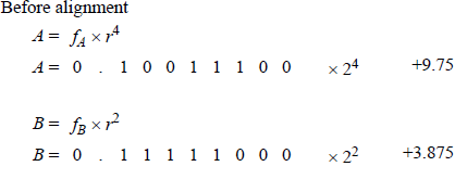
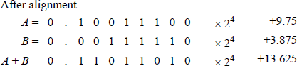
The fractions must be properly aligned before addition can take place; therefore, the fraction with the smaller exponent is shifted right and the exponent is adjusted by increasing the exponent by one for each bit position shifted.
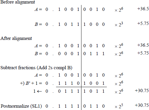
Figure 11.11 shows an example of floating-point addition when adding and , in which the 8-bit fractions are not properly aligned initially and post-normalization is required. Postnormalization occurs when the resulting fraction overflows, requiring a right shift of one bit position with a corresponding increment of the exponent. The bit causing the overflow is shifted right into the high-order fraction bit position.
The alignment and shifting of the fractions is now summarized. Equation 11.3 states that if eA > eB, then fraction fA is added to the aligned fraction fB with the exponent eA assigned to the resulting sum. The radix points of the two operands must be aligned prior to the addition operation. This is achieved by comparing the relative magnitudes of the two exponents. The fraction with the smaller exponent is then shifted | eA – eB | positions to the right.
The augend and addend are then added and the sum is characterized by the larger exponent. A carry-out of the high-order bit position may occur, yielding a result with an absolute value of 1 ≤ | result | < 2 before postnormalization.
11.4.1 Overflow and Underflow
The floating-point addition example of Figure 11.11 generated a carry-out of the highorder bit position, which caused a fraction overflow. When adding two numbers with the same sign, the absolute value of the result may be in the following range before postnormalization:
This indicates that the fraction is in the range of 1.000 . . . 0 to 1.111 . . .1. The overflow can be corrected by shifting the carry-out in concatenation with the fraction one bit position to the right and incrementing the exponent by 1. This operation is shown in Equation 11.4.
The term r−1 is the shifting factor that shifts the resulting fraction and the carry-out one bit position to the right. For radix 2, the shifting factor is 2 − 1 (or 1/2), which divides the result by 2 by executing a right shift of one bit position. The terms reA + 1 and reB + 1 increment the appropriate exponents by 1. Equation 11.3 is similar to Equation 11.4, but does not require a shift operation.
When aligning a fraction by shifting the fraction right and adjusting the exponent, bits may be lost off the right end of the fraction, resulting in a fraction underflow. This can be resolved by using a rounding method discussed in Section 11.1.1.
11.4.2 Add Instructions
There are different versions of the add instruction. One version, FADD, adds the single-operand floating-point destination operand in ST(0) of the register stack to a 32-bit or a 64-bit source operand in memory and stores the sum in ST(0). For some add instructions, the source operand can be a single-precision floating-point operand, a double-precision floating-point operand, an integer word operand, or an integer doubleword operand. The syntax for the FADD instruction is shown below.
FADD m32fp (memory, 32 bits, floating-point)
FADD m64fp (memory, 64 bits, floating-point)
Another version of the add instruction adds the operand in register ST(0) to the operand in register ST(i) and stores the sum in ST(0) as destination or in ST(i) as destination depending on syntax of the instruction, as shown below.
FADD ST(0), ST(i) (stores sum in destination ST(0))
FADD ST(i), ST(0) (stores sum in destination ST(i))
Another version of the add instruction, FADDP, is similar to the double-operand version shown above, where the sum is stored in ST(i). However, in this version the register stack is popped after the sum is stored. The syntax is shown below.
FADDP ST(i), ST(0)
Another version of the add instruction, FADDP, is the no-operand version, which adds the operand in ST(0) to the operand in ST(1) and stores the sum in ST(1), then pops the register stack. The syntax is shown below.
FADDP
Another version of the add instruction, FIADD, adds the operand in ST(0) of the register stack to a 16-bit or a 32-bit integer source operand in memory and stores the sum in ST(0). The FIADD instruction converts the integer source operand to a double extended-precision floating-point number before adding it to ST(0). The syntax is shown below.
FIADD m16int (memory, 16 bits, integer)
FIADD m32int (memory, 32 bits, integer)
Figure 11.12 shows an assembly language module embedded in a C program that illustrates utilizing different versions of the FADD instruction. The FADD singleoperand and the FADD double-operand instructions are used in the program. Two floating-point numbers are entered from the keyboard for use in the program. The initialize floating-point unit (FINIT) can be used to initialize the register stack. This instruction does not change the contents of the stack; however, each register is tagged as being empty — the tag register is set to 112.
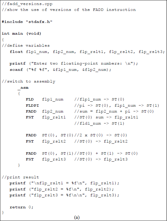
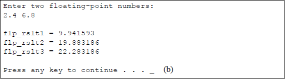
Program to illustrate using versions of the FADD instruction: (a) the program and (b) the outputs.
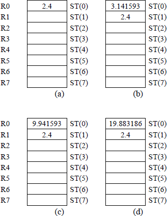
Figure 11.13 shows the register stack contents for different stages of the program. Figure 11.13(a) shows the result of flp1_num (2.4) being pushed onto the register stack. Then the value of pi (≈3.141593) is pushed onto the stack as shown in Figure 11.13(b). Next the FADD instruction adds flp2_num (6.8) to pi and stores the sum (9.941593) in ST(0), as shown in Figure 11.13(c). Then ST(0) is doubled (19.883186), as shown in Figure 11.13(d). Finally, ST(0) is added to ST(1) — 19.883186 + 2.4 = 22.283186 and stored in ST(0).
11.5 Subtraction Instructions
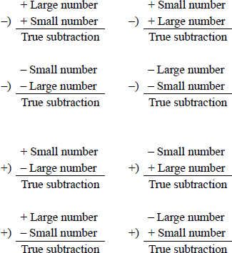
Floating-point subtraction also requires that the fractions be aligned before subtracting. Fraction overflow can also occur in subtraction since subtraction is accomplished by adding the 2s complement of the subtrahend. The subtraction of two fractions is identical to the subtraction algorithm presented in fixed-point addition. If the signs of the operands are the same () and the operation is subtraction, then this is referred to as true subtraction and the fractions are subtracted. If the signs of the operands are different () and the operation is addition, then this is also specified as true subtraction. True subtraction corresponds to one of the following conditions:
As in fixed-point notation, the same hardware can be used for both floating-point addition and subtraction to add or subtract the fractions. All operands will consist of normalized fractions properly aligned with biased exponents. Floating-point subtraction is defined as shown in Equation 11.5 for two numbers A and B, where and .
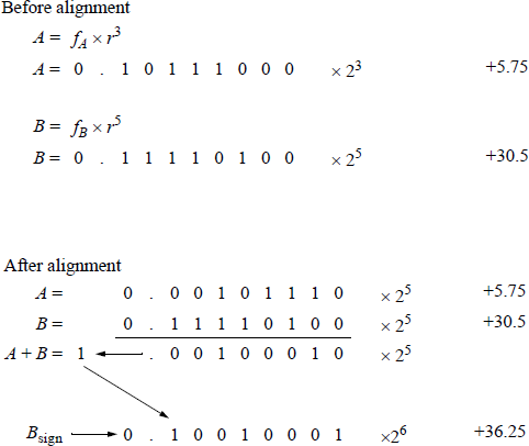
The terms and in Equation 11.5 are analogous to the terms used in floating-point addition. These terms are called shifting factors to shift the fraction with the smaller exponent. This is equivalent to a divide operation, since is equivalent to , which is a right shift. For , fraction fB is shifted right the number of bits specified by the absolute value of . An example of using the shifting factor for subtraction is shown in Figure 11.14 for two operands, A = +36.5 and B = +5.75. Since the implied 1 is part of the fractions, it must be considered when subtracting two normalized floating-point numbers — the implied 1 is shown as the high-order bit in Figure 11.14.
11.5.1 Numerical Examples
Subtraction can yield a result that is either true addition or true subtraction. True addition produces a result that is the sum of the two operands disregarding the signs; true subtraction produces a result that is the difference of the two operands disregarding the signs. There are four cases that yield a true addition, as shown in Figure 11.15, and eight cases that yield a true subtraction, as shown in Figure 11.16.
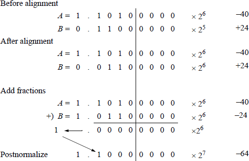
An example of true addition is shown in Figure 11.17 in which +24 is subtracted from –40 to yield a result of –64.
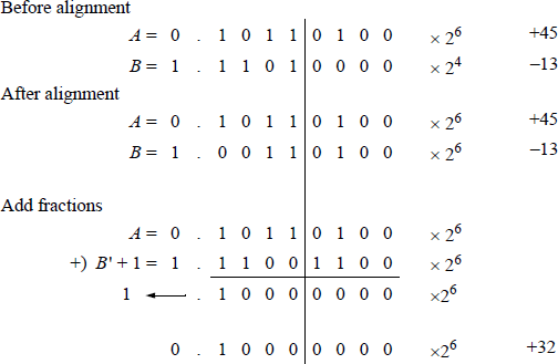
An example of true subtraction is shown in Figure 11.18 in which –13 is added to +45 to yield a result of +32.
11.5.2 Subtract Instructions
There are different versions of the subtract instruction. One version, FSUB, subtracts the single-operand floating-point 32-bit or a 64-bit source operand in memory from ST(0) of the register stack and stores the difference in ST(0). For some subtract instructions, the source operand can be a single-precision floating-point operand, a double-precision floating-point operand, an integer word operand, or an integer doubleword operand. The syntax for the FSUB instruction is shown below.
FSUB m32fp (memory, 32 bits, floating-point)
FSUB m64fp (memory, 64 bits, floating-point)
Another version of the subtract instruction subtracts the operand in register ST(i) from the operand in register ST(0) and stores the difference in ST(0). A similar version subtracts ST(0) from ST(i) and stores the difference in ST(i). The syntax for the two-operand FSUB instruction is shown below.
FSUB ST(0), ST(i) (stores difference in ST(0))
FSUB ST(i), ST(0) (stores difference in ST(i))
Another version of the subtract instruction, FSUBP, is similar to the double-operand version shown above, where the difference is stored in ST(i). The operand in ST(0) is subtracted from the operand in ST(i) and the difference is stored in ST(i). However, in this version the register stack is popped after the difference is stored. The syntax is shown below.
FSUBP ST(i), ST(0)
Another version of the subtract instruction, FSUBP, is the no-operand version, which subtracts the operand in ST(0) from the operand in ST(1) and stores the difference in ST(1), then pops the register stack. The syntax is shown below.
FSUBP
Another version of the subtract instruction, FISUB, subtracts the 16-bit or a 32-bit single-operand integer source operand in memory from ST(0) and stores the difference in ST(0). The FISUB instruction converts the integer source operand to a double extended-precision floating-point number before subtracting it from ST(0). The syntax is shown below.
FISUB m16int (memory, 16 bits, integer)
FISUB m32int (memory, 32 bits, integer)
There are also a variety of reverse subtract instructions. These instructions are similar to those listed above, except that the subtract operation is reversed. For example, the FSUBR instruction subtracts ST(0) from the single-operand floating-point 32bit or a 64-bit source operand in memory stores the difference in ST(0). These instructions include the following:
FSUBR m32fp (memory, 32 bits, floating-point,
subtracts ST(0) from memory and
stores the difference in ST(0))
FSUBR m64fp (memory, 64 bits, floating-point,
subtracts ST(0) from memory and
stores the difference in ST(0))FSUBR ST(0), ST(i) (subtracts ST(0) from ST(i) and
stores the difference in ST(0))
FSUBR ST(i), ST(0) (subtracts ST(i) from ST(0) and
stores the difference in ST(i))
FSUBRP ST(i), ST(0) (subtracts ST(i) from ST(0),
stores the difference in ST(i),
then pops stack)
FSUBRP (subtracts ST(1) from ST(0),
stores the difference in ST(1),
then pops stack)
FISUBR m16int (memory, 16 bits, integer,
subtracts ST(0) from the integer
in memory and stores the difference
in ST(0)
FISUBR m32int (memory, 32 bits, integer,
subtracts ST(0) from the integer
in memory and stores the difference
in ST(0))
The advantage of using the reverse subtraction instructions is that it is not necessary to exchange the operand in ST(0) with the operand in another register in the stack in order to perform a subtraction.
Figure 11.19 shows an assembly language module embedded in a C program that illustrates utilizing different versions of the FSUB instruction. The FSUB single-operand instruction, the FSUB double-operand instruction, and the FSUBP instruction are used in the program. Four floating-point numbers are entered from the keyboard for use in the program: two negative numbers and two positive numbers, as shown below. The results of the five subtract instructions are also shown below.
flp1_num = -296.125
flp2 num = -77.625
flp3_num = +156.750
flp4_num = +127.500
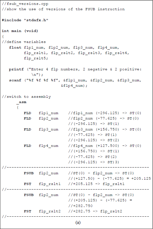
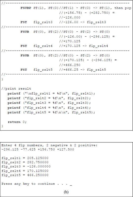
Program to illustrate using versions of the FSUB instruction: (a) the program and (b) the outputs.
The initialize floating-point unit (FINIT) can be used to initialize the register stack. This instruction does not change the contents of the stack; however, each register is tagged as being empty — the tag register is set to 112.

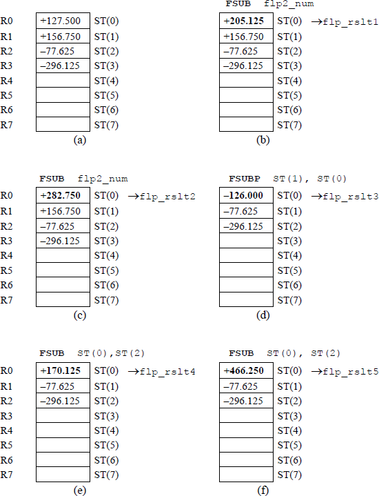
Figure 11.20 shows the register stack contents for different stages of the program. Figure 11.20(a) shows the result of the four floating-point numbers having been pushed onto the register stack. The remaining figures in Figure 11.20 portray the results of the various instructions after they have been executed.
11.6 Multiplication Instructions
In floating-point multiplication, the fractions are multiplied and the exponents are added. Floating-point multiplication is simpler than floating-point addition or subtraction because there is no comparison of exponents and no alignment of fractions. Fraction multiplication and exponent addition are two independent operations and can be done in parallel. Floating-point multiplication is defined as shown in Equation 11.6.
The sign of the product is determined by the signs of the operands as shown below.
11.6.1 Double Bias
An n-bit multiplicand (A) and an n-bit multiplier (B) generate a 2n-bit product (P), which, in conjunction with the exponent, should be of sufficient precision. Although it is not apparent in the numerical paper-and-pencil floating-point multiplication examples in the next section, there is a minor problem when adding two biased exponents. Since both exponents are biased, there will be a double bias in the resulting exponent, as shown below.
The resulting exponent should be restored to a single bias before the multiplication operation begins. This is accomplished by subtracting the bias.
Check for zero operands. If A = 0 or B = 0, then the product = 0.
Determine the sign of the product.
Add exponents and subtract the bias.
Multiply fractions. Steps 3 and 4 can be done in parallel, but both must be completed before step 5.
Normalize the product.
An example will illustrate this concept. Let the exponents be and . Each exponent will be biased, then added to produce a double bias. The bias will then be subtracted to produce a single bias, then subtracted again to produce the sum of the two unbiased exponents: and .
Restore to single bias by subtracting the bias; that is, by adding the 2s complement of 0111 1111 (1000 0001).
11.6.2 Numerical Examples
Examples will now be presented that illustrate multiplication using the paper-and-pen-cil method for 4-bit operands in 2s complement notation. If the operands are in 2s complement notation, then the sign bit is treated in a manner identical to the other bits; however, the sign bit of the multiplicand is extended left in the partial product to accommodate the 2n-bits of the product. The only requirement is that the multiplier must be positive — the multiplicand can be either positive or negative. This is not a problem when using the X86 assembly language — the assembler resolves this problem automatically. The assembler also resolves exponent biasing and significand alignment for addition and subtraction.
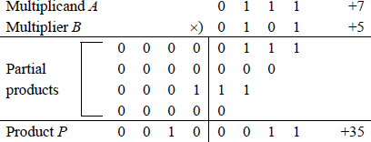
Example 11.1 The multiplicand and multiplier are two positive 4-bit operands, where and to yield a product . A multiplier bit of 1 copies the multiplicand to the partial product; a multiplier bit of 0 enters 0s in the partial product.
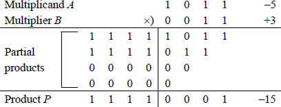
Example 11.2 This example multiplies a positive multiplicand by a negative multiplier to demonstrate that the multiplier must be positive. The multiplicand is ; the multiplier is . The product should be –15; however, since the multiplier is treated as an unsigned number (1101 = 13), the result is 0100 0001 (65).

The problem can be resolved by either 2s complementing both operands or by 2s complementing the multiplier, performing the multiplication, then 2s complementing the result. The method shown below 2s complements both operands.
When both operands are negative, the correct result can be obtained by 2s complementing both operands before the operation begins, since a negative multiplicand multiplied by a negative multiplier yields a positive product.
11.6.3 Multiply Instructions
There are different versions of the multiply instruction. One version, FMUL, multiplies the multiplicand in ST(0) by the single-operand floating-point 32-bit or a 64-bit multiplier source operand in memory and stores the product in ST(0). For some multiply instructions, the source operand can be a single-precision floating-point operand, a double-precision floating-point operand, an integer word operand, or an integer doubleword operand. The syntax for the FMUL instruction is shown below.
FMUL m32fp (memory, 32 bits, floating-point)
FMUL m64fp (memory, 64 bits, floating-point)
Another version of the multiply instruction multiplies the operand in register ST(0) by the operand in register ST(i) and stores the product in ST(0). A similar version multiplies ST(i) by ST(0) and stores the product in ST(i). The syntax for the two-operand FMUL instruction is shown below.
FMUL ST(0), ST(i) (stores product in ST(0))
FMUL ST(i), ST(0) (stores product in ST(i))
Another version of the multiply instruction, FMULP, is similar to the double-operand version shown above, where the product is stored in ST(i). The operand in ST(i) is multiplied by the operand in ST(0) and the product is stored in ST(i). However, in this version, the register stack is popped after the product is stored. The syntax is shown below.
FMULP ST(i), ST(0)
Another version of the multiply instruction, FMULP, is the no-operand version, which multiplies the operand in ST(1) by the operand in ST(0) and stores the product in ST(1), then pops the register stack. The syntax is shown below.
FMULP
Another version of the multiply instruction, FIMUL, multiplies ST(0) by the 16bit or a 32-bit single-operand integer source operand in memory and stores the product in ST(0). The FIMUL instruction converts the integer source operand to a double extended-precision floating-point number before the multiplication operation. The syntax is shown below.
FIMUL m16int (memory, 16 bits, integer)
FIMUL m32int (memory, 32 bits, integer)
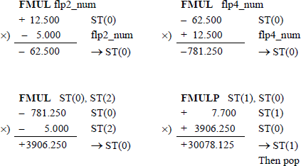
Figure 11.21 shows an assembly language module embedded in a C program that illustrates utilizing different versions of the FMUL instruction. The FMUL singleoperand instruction, the FMUL double-operand instruction, and the FMULP instruction are used in the program. Four floating-point numbers are entered from the keyboard for use in the program: two negative numbers and two positive numbers, as shown below. The results of the five multiply instructions are also shown below.
flp1_num = −10.500
flp2_num = −5.000
flp3_num = +7.700
flp4_num = +12.500
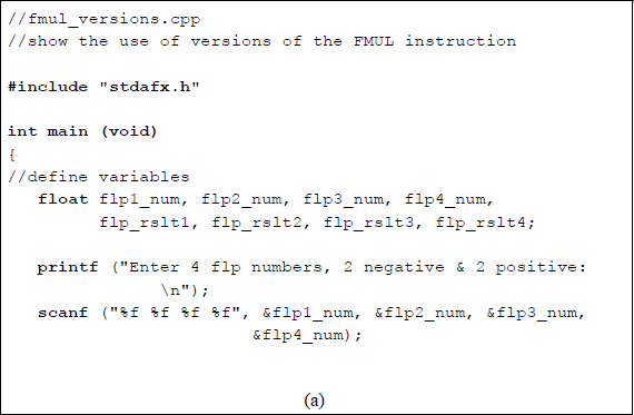
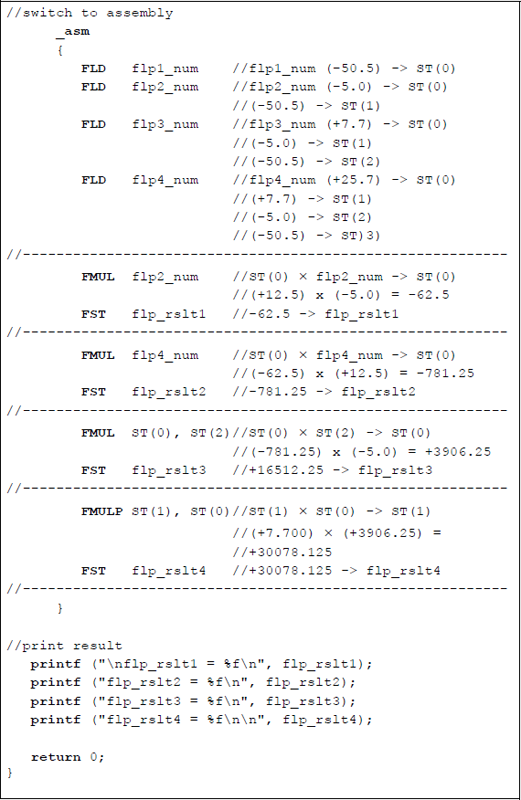
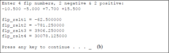
Program to illustrate using versions of the FMUL instruction: (a) the program and (b) the outputs.
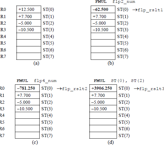
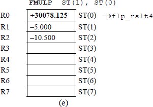
Figure 11.22 shows the register stack contents for different stages of the program. Figure 11.22(a) shows the result of the four floating-point numbers having been pushed onto the register stack. The remaining figures in Figure 11.22 portray the results of the various instructions after they have been executed.
An example of floating-point multiplication is shown in Figure 11.23 to illustrate the concept of adding the exponents to obtain the correct resulting exponent. The example uses the sequential add-shift method with 8-bit operands. In this example, the multiplicand fraction is multiplied by a multiplier with partial product to produce a product of .
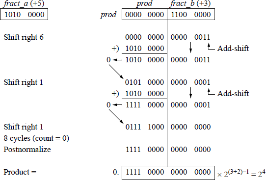
Since the multiplication involves two n-bit operands, a count-down sequence counter, count, is set to a value that represents the number of bits in one of the operands. The counter is decremented by one for each step of the add-shift sequence. When the counter reaches a value of zero, the operation is finished and the product is normalized, if necessary.
If the low-order bit of register fract_b is equal to zero, then zeroes are added to the partial product and the sum is loaded into register prod. In this case, it is not necessary to perform an add operation — a right shift can accomplish the same result. The sequence counter is then decremented by one. If the low-order bit of register fract_b is equal to one, then the multiplicand is added to the partial product. The sum is loaded into register prod and the sequence counter is decremented.
11.7 Division Instructions
Floating-point division performs two operations in parallel: fraction division and exponent subtraction. The dividend is usually 2n bits and the divisor is n bits. Divide overflow is determined in the same way as in fixed-point division; that is, if the highorder half of the dividend is greater than or equal to the divisor, then divide overflow occurs. The problem is resolved by shifting the dividend right one bit position and incrementing the exponent by one. Since both operands were normalized, this assures that the entire dividend is smaller than the divisor, as shown below.
This is referred to as dividend alignment, providing the ranges for the two operands, as shown below.
Both operands are checked for a value of zero. If the dividend is zero, then the exponent, quotient, and remainder are set to zero. If the divisor is zero, then the result is infinity and the operation is terminated. Division is performed on normalized floating-point operands A and B using biased exponents, such that
where f is the normalized fraction, e is the exponent, and r is the radix. Floating-point division is defined as shown in Equation 11.7, which shows fraction division and exponent subtraction performed simultaneously.
The sign of the quotient is determined by the signs of the floating-point numbers. If the signs are the same, then the sign of the quotient is positive; if the signs are different, then the sign of the quotient is negative. This can be determined by the exclusive-OR of the two signs, as shown in Equation 11.8. The sign of the remainder is the same as the sign of the dividend.
11.7.1 Zero Bias
As was stated previously, the divisor exponent is subtracted from the dividend exponent in parallel with fraction division. The exponents are subtracted and the carry-out is examined. If the carry-out = 1, then the dividend exponent was greater than or equal to the divisor exponent (eA ≥ eB). If the carry-out = 0, then the dividend exponent was less than the divisor exponent (eA < eB). Since both exponents were initially biased, the difference generates a result with no bias, as shown in Equation 11.9.
Therefore, the bias must be added to the difference so that the resulting exponent is properly biased. Thus, for the single-precision format:
Restoring the bias may result in an exponent overflow, in which case the division operation is terminated. Examples will now be presented that illustrate the previous statements and are chosen for , , and .
Example 11.3 , where and . Therefore, .
Restore to single bias by adding the bias.
Example 11.4 Let , where and . Therefore, .
Restore to single bias by adding the bias.
Example 11.5 Let and . Therefore, .
If carry-out = 0, then 2s complement to obtain the difference of 0000 1010 (10).
Restore to single bias by adding the bias.
11.7.2 Numerical Example
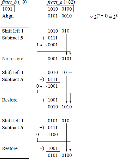
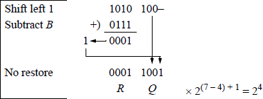
This section presents a numerical example using the sequential shift-subtract/add restoring division method with 4-bit divisors and 8-bit dividends. Register A contains the 2n-bit normalized dividend fraction, fract_a, which will eventually contain the n-bit quotient and n-bit remainder. Register B contains the n-bit normalized divisor fraction, fract_b.
Since the division process involves one n-bit divisor and one 2n-bit dividend, a count-down sequence counter, count, is set to a value that represents the number of bits in the divisor. The counter is decremented by one for each step of the shift-subtract/add sequence. When the counter reaches a value of zero, the operation is finished and the quotient resides in fract_a[3:0] and the remainder resides in fract_a[7:4].
If the value of the high-order half of the dividend is greater than or equal to the value of the divisor, then an overflow condition exists. To resolve this problem, the dividend is shifted right one bit position and the dividend exponent is incremented by one. Each sequence in the division process consists of a shift left of one bit position followed by a subtraction of the divisor.
Example 11.6 A dividend fraction is divided by a divisor fraction to yield a quotient of and a remainder of , as shown in Figure 11.24.
The example of Figure 11.24 was presented only to provide a review of the sequential shift-subtract/add restoring division algorithm and does not reflect the floating-point division procedure. Floating-point division yields a quotient only — there is no remainder. For example, the operands of Figure 11.24 will yield a floatingpoint result of 9.111111; that is, 82 / 9 = quotient of 9 and a remainder of . This is shown in the program of Figure 11.25, using the FDIV instruction, which is explained in Section 11.7.3. The remainder can be obtained by using the partial remainder FPREM1 instruction described in Section 11.10.
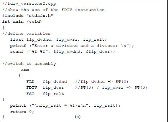
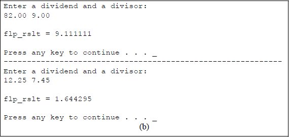
Program to show a divide operation of 82.00 / 9.00 to yield a quotient of 9.111111: (a) the program and (b) the outputs.
11.7.3 Divide Instructions
There are different versions of the divide instruction. One version, FDIV, divides the dividend in ST(0) by the single-operand floating-point 32-bit or a 64-bit divisor source operand in memory and stores the result in ST(0). For some divide instructions, the source operand can be a single-precision floating-point operand, a double-precision floating-point operand, an integer word operand, or an integer doubleword operand. The syntax for the FDIV instruction is shown below.
FDIV m32fp (memory, 32 bits, floating-point)
FDIV m64fp (memory, 64 bits, floating-point)
Another version of the divide instruction divides the operand in register ST(0) by the operand in register ST(i) and stores the result in ST(0). A similar version divides ST(i) by ST(0) and stores the result in ST(i). The syntax for the two-operand FDIV instruction is shown below
FDIV ST(0), ST(i) (stores result in ST(0))
FDIV ST(i), ST(0) (stores result in ST(i))
Another version of the divide instruction, FDIVP, is similar to the double-operand version shown above, where the result is stored in ST(i). The operand in ST(i) is divided by the operand in ST(0) and the result is stored in ST(i). However, in this version, the register stack is popped after the result is stored. The syntax is shown below.
FDIVP ST(i), ST(0)
Another version of the divide instruction, FDIVP, is the no-operand version, which divides the operand in ST(1) by the operand in ST(0) and stores the result in ST(1), then pops the register stack. The syntax is shown below.
FDIVP
Another version of the divide instruction, FIDIV, divides ST(0) by the 16-bit or 32-bit integer source operand in memory and stores the result in ST(0). The FIDIV instruction converts the integer source operand to a double extended-precision floating-point number before the division operation. The syntax is shown below.
FIDIV m16int (memory, 16 bits, integer)
FIDIV m32int (memory, 32 bits, integer)
There are also a variety of reverse divide instructions. These instructions are similar to those listed above, except that the divide operation is reversed. For example, the FDIVR instruction divides the single-operand floating-point 32-bit or a 64-bit source operand in memory by ST(0) stores the result in ST(0). These instructions include the following:
FDIVR m32fp (memory, 32 bits, floating-point,
divides memory operand by ST(0) and
stores the result in ST(0))
FDIVR m64fp (memory, 64 bits, floating-point,
divides memory operand by ST(0) and
stores the result in ST(0))FDIVR ST(0), ST(i) (divides ST(i) by ST(0) and
stores the result in ST(0))
FDIVR ST(i), ST(0) (divides ST(0) by ST(i) and
stores the result in ST(i))FDIVRP ST(i), ST(0) (divides ST(0) by ST(i),
stores the result in ST(i),
then pops stack)FDIVRP (divides ST(0) by ST(1),
stores the result in ST(1),
then pops stack)FIDIVR m16int (memory, 16 bits, integer,
divides memory operand by ST(0) and
stores the result in ST(0))
FIDIVR m32int (memory, 32 bits, integer,
divides memory operand by ST(0) and
stores the result in ST(0))
Figure 11.26 shows an assembly language module embedded in a C program that illustrates utilizing different versions of the FDIV instruction. The FDIV single-operand instruction, the FDIV double-operand instruction, and the FDIVP instruction are used in the program. Four floating-point numbers are entered from the keyboard for use in the program: a positive and negative dividend and a positive and negative divisor, as shown below. The results of the four divide instructions are also shown below.
flp1_dvdnd = +547.125
flp2_dvdnd = −15.750
flp1_dvsr = +65.175
flp2_dvsr = −50.650
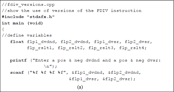
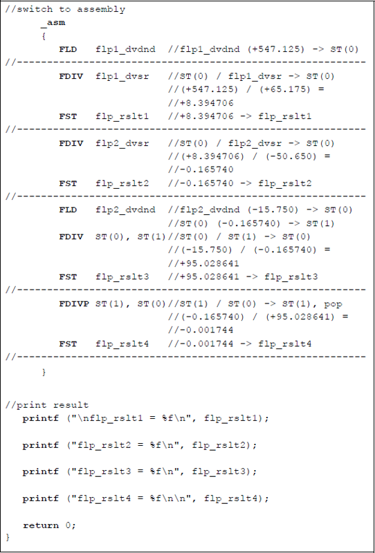
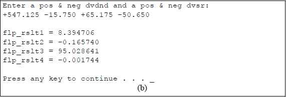
Program to illustrate using versions of the FDIV instruction: (a) the program and (b) the outputs.
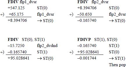
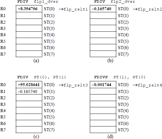
Figure 11.27 shows the register stack contents for different stages of program execution for Figure 11.26. The floating-point number flp1_dvdnd is initially stored in ST(0) by the first load instruction. Figure 11.27(a) through Figure 11.27(d) portray the results of the various instructions after they have been executed.
11.8 Compare Instructions
This section describes the floating-point instructions that compare different types of data. These include the compare floating-point values instructions: FCOM, FCOMP, and FCOMPP; the compare floating-point values and set flags instructions: FCOMI, FCOMIP, FUCOMI, and FUCOMIP; the compare integer instructions: FICOM and FICOMP; the test instruction: FTST; and the unordered compare floating-point values instructions: FUCOM, FUCOMP, and FUCOMPP. These instructions are explained in the sections that follow.
11.8.1 Compare Floating-Point Values
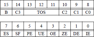
There are nine compare floating-point values instructions that compare the contents of stack register ST(0) with the source operand. The condition code flags are then set in the floating-point unit (FPU) status word or in the EFLAGS register, depending on the type of instruction and the results of the operation. The FPU status word is reproduced in Figure 11.28 and the EFLAGS register is reproduced in Figure 11.29.

The meaning of bits C3, C2, and C0 in the floating-point unit status word are defined in Table 11.1. Bits C3, C2, and C0 map into bits ZF, PF, and CF, respectively in the EFLAGS register. Unlike integer comparison instructions, floating-point comparison instructions have four — rather than three — results: ST(0) greater than source, ST(0) less than source, ST(0) equal to source, and unordered. An unordered condition is detected if an operand is not-a-number (NaN) or is in an undefined format. In this case, a floating-point invalid-operation exception (#IA) is produced. If the #IA exception is masked, then the condition code flags are set to the unordered state.
X87 Condition Code Flags in the FPU Status Word for the Compare Floating-Point Values Instructions
Condition |
C3 |
C2 |
C1 |
C0 |
|---|---|---|---|---|
ST(0) > source |
0 |
0 |
− |
0 |
ST(0) < source |
0 |
0 |
− |
1 |
ST(0) = source |
1 |
0 |
− |
0 |
Unordered |
1 |
1 |
− |
1 |
There are different versions of the compare floating-point values instruction. The source operand can be a register in the FPU stack or a memory location. However, if no source operand is given, then the operand in ST(0) is compared with the operand in ST(1).
One version, FCOM, compares the operand in ST(0) with the floating-point 32-bit or a 64-bit source operand in memory and sets the X87 FPU condition code flags. The syntax for the FCOM instruction is shown below.
FCOM m32fp (memory, 32-bit floating-point)
FCOM m64fp (memory, 64-bit floating-point)
Another version of the FCOM instruction compares the operand in register ST(0) with the operand in register ST(i) and sets the X87 FPU condition code flags. The syntax is shown below.
FCOM ST(i) (compare ST(0) with ST(i))
Another version of the FCOM instruction compares the operand in register ST(0) with the operand in register ST(1) and sets the X87 FPU condition code flags. This version does not define a source operand. The syntax is shown below.
FCOM (compare ST(0) with ST(1))
Another version, FCOMP, of the instruction compares the operand in register ST(0) with the floating-point 32-bit or a 64-bit source operand in memory, sets the X87 FPU condition code flags, then pops the register stack. The syntax is shown below.
FCOMP m32fp (memory, 32-bit floating-point, pop stack)
FCOMP m64fp (memory, 64-bit floating-point, pop stack)
Another version of the FCOMP instruction compares the operand in register ST(0) with the operand in ST(i), sets the X87 FPU condition code flags, then pops the register stack. The syntax is shown below.
FCOMP ST(i) (compare ST(0) with ST(i), pop stack)
Another version of the FCOMP instruction compares the operand in register ST(0) with the operand in ST(1), sets the X87 FPU condition code flags, then pops the register stack. This version does not define a source operand. The syntax is shown below.
FCOMP (compare ST(0) with ST(1), pop stack)
Another version of the instruction compares the operand in register ST(0) with the operand in ST(1), sets the X87 FPU condition code flags, then pops the register stack twice. This version does not define a source operand. The syntax is shown below.
FCOMPP (compare ST(0) with ST(1), pop stack twice)
11.8.2 Compare Floating-Point Values and Set EFLAGS
These instructions perform an unordered comparison of the operands in stack registers ST(0) and ST(i). The result of the comparison sets the zero flag (ZF), the parity flag (PF), and the carry flag (CF) in the EFLAGS register, as shown in Table 11.2.
Status Flag Bits for the Compare Floating-Point Values and Set EFLAGS Instructions
Condition |
ZF |
PF |
CF |
|---|---|---|---|
ST(0) > source |
0 |
0 |
0 |
ST(0) < source |
0 |
0 |
1 |
ST(0) = source |
1 |
0 |
0 |
Unordered |
1 |
1 |
1 |
An unordered comparison checks the type of numbers being compared; for example, unsupported, NaN, normal finite, infinity, zero, empty, or denormal. Denormal-ized numbers are very small numbers, where the biased exponent is zero and there are leading zeroes in the significand (fraction). There are four different versions of this type of instruction, which are described below. Each version has two operands and there is no destination.
One version, FCOMI, compares the operand in register stack ST(0) with the operand in register stack ST(i), then sets the three status flags in the EFLAGS register, as shown in Table 11.2. This instruction operates identically to the FCOM instruction, but sets the status flags in the EFLAGS register instead of the condition code flags in the X87 FPU status word register. The syntax is shown below.
FCOMI ST(0), ST(i) (compare ST(0) with ST(i), set flags)
Another version, FCOMIP, compares the operand in register stack ST(0) with the operand in register stack ST(i), sets the three flags in the EFLAGS register, then pops the register stack. This instruction operates identically to the FCOM instruction, but sets the status flags in the EFLAGS register instead of the condition code flags in the X87 FPU status word register. The syntax is shown below.
FCOMIP ST(0), ST(i) (compare ST(0) with ST(i),
set status flags, then pop stack)
Another version, FUCOMI, compares the operand in register stack ST(0) with the operand in register stack ST(i) for ordered operands, then sets the status flags in the EFLAGS register instead of the condition code flags in the X87 FPU status word register. This instruction operates identically to the FCOMI instruction, but does not yield a floating-point invalid-operation exception. The syntax is shown below.
FUCOMI ST(0), ST(i) (compare ST(0) with ST(i)
for ordered operands,
then set status flags)
Another version, FUCOMIP, compares the operand in register stack ST(0) with the operand in register stack ST(i) for ordered operands, sets the status flags in the EFLAGS register instead of the condition code flags in the X87 FPU status word register, then pops the register stack. This instruction operates identically to the FCOMIP instruction, but does not yield a floating-point invalid-operation exception, except for NaNs or unsupported formats. The syntax is shown below.
FUCOMIP ST(0), ST(i) (compare ST(0) with ST(i)
for ordered operands,
set status flags,
then pop stack)
11.8.3 Compare Integer
There are two different versions of the compare integer instruction, both of which are described below. The operation of both versions, FICOM and FICOMP, is identical to the operation of the FCOM and FCOMP instructions; however, the source operand is an integer in a memory location. The integer operand is changed to a double extended-precision floating-point value before the operands are compared.
One version, FICOM, compares ST(0) with a 16-bit or 32-bit integer source operand in memory, then sets the condition code flags in the X87 floating-point unit status word. Refer to Table 11.1 for the meaning of bits C3, C2, and C0. The syntax is shown below.
FICOM m16int (compare ST(0) with a 16-bit integer
in memory, then set flags)
FICOM m32int (compare ST(0) with a 32-bit integer
in memory, then set flags)
Another version, FICOMP, compares ST(0) with a 16-bit or 32-bit integer source operand in memory, sets the condition code flags in the X87 floating-point unit status word, then pops the register stack. The syntax is shown below.
FICOMP m16int (compare ST(0) with a 16-bit integer
in memory, set flags,
then pop stack)FICOMP m32int (compare ST(0) with a 32-bit integer
in memory, set flags,
then pop stack)
11.8.4 Test
This instruction, FTST, performs an operation identical to the FCOM instruction, but compares the operand in ST(0) with a value of 0.0, then sets the condition code flags — C3, C2, C0 — in the X87 floating-point unit status word. The syntax is shown below.
FTST (compare ST(0) with 0.0)
11.8.5 Unordered Compare Floating-Point Values
There are different versions of the unordered compare floating-point values instruction, all of which are described below. The operation of FUCOM, FUCOMP, and FUCOMPP are identical to the operation of the FCOM, FCOMP, and FCOMPP instructions, respectively. However, the floating-point invalid-operation exception is set only when one or both operands are an SNaN (defined below) or are in an unsupported format. When one or both operands are a QNaN (defined below), the condition code flags are set to unordered and do not set the floating-point invalid-operation exception.
There are two types of NaNs that are used in the architecture. An SNaN is defined as a signaling NaN, in which the high-order significand bit is reset. A QNaN is defined as a quiet NaN, in which the high-order significand bit is set. These instructions execute an unordered comparison of ST(0) with ST(i) or ST(1) and set the condition code flags — C3, C2, C0 — in the X87 floating-point unit status word.
One version, FUCOM, compares ST(0) with ST(i), then sets the condition code flags in the X87 floating-point unit status word. Refer to Table 11.1 for the meaning of bits C3, C2, and C0. The syntax is shown below.
FUCOM ST(i) (compare ST(0) with ST(i), set flags)
Another version, FUCOM with no operand, compares ST(0) with ST(1), then sets the condition code flags in the X87 floating-point unit status word. Refer to Table 11.1 for the meaning of bits C3, C2, and C0. The syntax is shown below.
FUCOM (compare ST(0) with ST(1), set flags)
Another version, FUCOMP, compares the operand in register stack ST(0) with the operand in register stack ST(i), sets the condition code flags in the X87 floating-point unit status word, then pops the register stack. Refer to Table 11.1 for the meaning of bits C3, C2, and C0. The syntax is shown below.
FUCOMP ST(i) (compare ST(0) with ST(i),
set flags, then pop stack)
Another version, FUCOMP with no operand, compares the operand in register stack ST(0) with the operand in register stack ST(1), sets the condition code flags in the X87 floating-point unit status word, then pops the register stack. Refer to Table 11.1 for the meaning of bits C3, C2, and C0. The syntax is shown below.
FUCOMP (compare ST(0) with ST(1),
set flags, then pop stack)
Another version, FUCOMPP with no operand, compares the operand in register stack ST(0) with the operand in register stack ST(1), sets the condition code flags in the X87 floating-point unit status word, then pops the register stack twice. Refer to Table 11.1 for the meaning of bits C3, C2, and C0. The syntax is shown below.
FUCOMPP (compare ST(0) with ST(1),
set flags, then pop stack twice)
A pop operation on the register stack is accomplished by setting the stack top tag register to a value of 112, indicating empty. Then the stack pointer is incremented by 1 — bits 13 through 11 (TOS) of the X87 floating-point status word, reproduced in Figure 11.30.
11.9 Trigonometric Instructions
This section describes the floating-point instructions that calculate the cosine FCOS, partial tangent FPTAN, sine FSIN, sine and cosine FSINCOS, and partial arctangent FPATAN of source operands that are expressed in radians. These instructions are explained in the sections that follow.
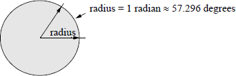
A radian is defined as an angular measurement that is equal to the angle at the center of a circle subtended by an arc that is equal to the radius of the circle. One radian is approximately equal to 57.296 degrees. Figure 11.31 shows a drawing that illustrates one radian. Since one radian ≈ 57.296 degrees, therefore, one degree ≈ 0.01745 radians.
11.9.1 Cosine
The cosine, FCOS, instruction calculates the cosine of the source operand — given in radians — in the stack top register ST(0) and stores the result in ST(0). If the operand is not within a specified range (–263 to +263), then bit C2 is set in the floating-point unit status word. This however, does alter the operand in ST(0) and does not generate an exception. The syntax is shown below and has no operands specified, because the source operand was previously loaded into ST(0).
FCOS (cosine -> ST(0))
11.9.2 Partial Arctangent
The partial arctangent, FPATAN, instruction is the inverse tangent function specified by tan−1 or arctan. The arctangent can be defined as follows:
The domain of the arctangent function is normally in the interval −π/2 to +π/2, as shown in Figure 11.32. The tangent function yields the ratio of the opposite / adjacent sides of a right triangle; the arctangent yields the angle of the ratio.
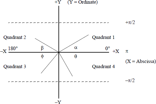
The FPATAN instruction has no operands specified in the instruction. It calculates the arctangent of the source operand in ST(1) divided by the second source operand in ST(0), then pops the register stack, which places the result in ST(0). The abscissa (X) is in ST(0) and the ordinate Y is in ST(1). The FPATAN instruction yields the angle between the X axis and the line drawn from the origin — center of the circle — to a point (X,Y) in a particular quadrant, as shown in Figure 11.32.
Since there are four quadrants, the angles in the quadrants have the following X and Y coordinates: (+X, +Y) in quadrant 1, (–X, +Y) in quadrant 2, (–X, –Y) in quadrant 3, (+X, –Y) in quadrant 4. The angle is a function of the sign of both X (the abscissa) and Y (the ordinate). An X, Y coordinate in quadrant 1 yields a positive angle; an X, Y coordinate in quadrant 2 yields an angle between π/2 and π an X, Y coordinate in quadrant 3 yields an angle between –π/2 and –π, and an X, Y coordinate in quadrant 4 yields an angle between 0 and −π/2.
Figure 11.33 shows a short assembly language module embedded in a C program that illustrates the application of the FPATAN instruction. The inputs represent the opposite (ordinate y) and the adjacent (abscissa x) sides of a right triangle. The first set of inputs (+1.0, +1.0) represent a 45 degree angle in quadrant 1 whose arctangent is 0.785398 radians. The second set of inputs (+1.0, +1.75) represent a 30 degree angle, also in quadrant 1, whose arctangent is 0.519146 radians. The third set of inputs (+1.0, –1.75) represents a 30 degree angle in quadrant 2, whose arctangent is 2.622447 radians — an angle between π/2 (1.570796) and π (3.141592).
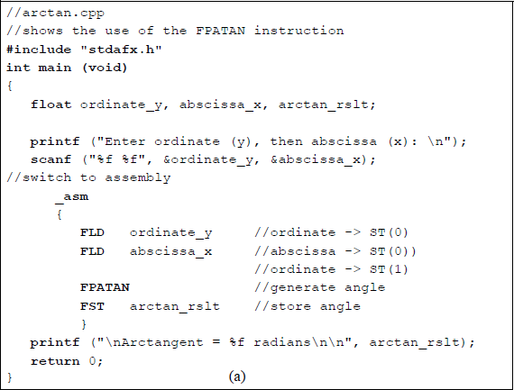

Program to illustrate the use of the partial arctangent FPATAN: (a) the program and (b) the outputs.
The fourth set of inputs (−1.0, −1.75) represent a 30 degree angle in quadrant 3 whose arctangent is −2.622447 radians — an angle between −π/2 (−1.570796) and −π (−3.141592). The fifth, and final, set of inputs (−1.0, +1.75) represent a 30 degree angle in quadrant 4 whose arctangent is −0.519146 radians — an angle between 0 and −π/2 (−1.570796).
11.9.3 Partial Tangent
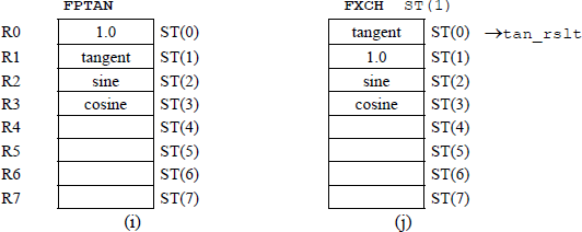
The partial tangent, FPTAN, instruction calculates the tangent of the source operand — expressed in radians — in ST(0) of the register stack, stores the result in ST(0), then pushes a value of +1.0 onto the stack, which maintains compatibility with X87 processors. The tangent for the angle θ of a right triangle is defined as follows: tan θ = opposite / adjacent.
11.9.4 Sine
The sine, FSIN, instruction calculates the sign of the source operand — expressed in radians — in ST(0) of the register stack, and stores the result in ST(0). If the operand is not within a specified range (–263 to +263), then bit C2 is set in the floating-point unit status word. This, however, does alter the operand in ST(0) and does not generate an exception. The syntax is shown below and has no operands specified, because the source operand was previously loaded into ST(0).
FSIN (sine -> ST(0)
Figure 11.34 shows an assembly language module embedded in a C program that illustrates the usage of the FSIN and FCOS instructions. The four sets of inputs are entered as radians.
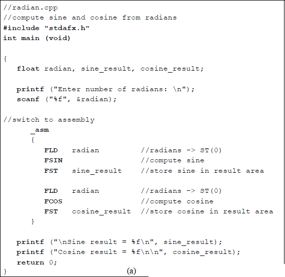
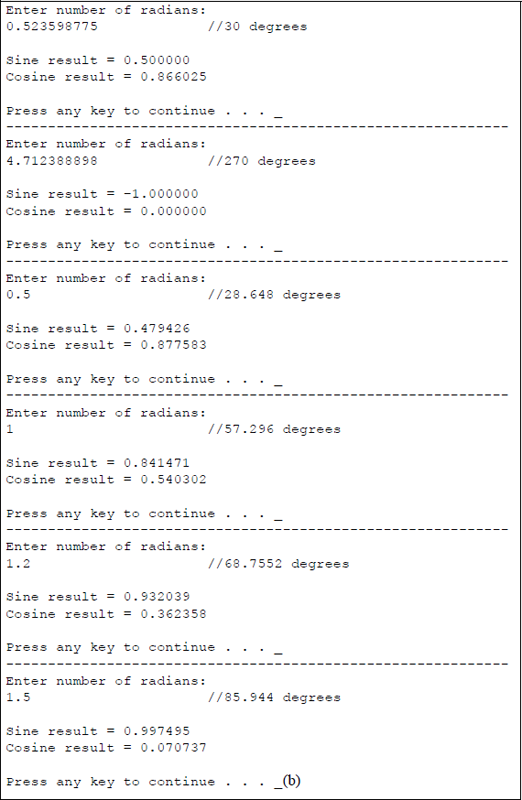
Program to illustrate the use of the FSIN and FCOS instructions: (a) the program and (b) the outputs.
11.9.5 Sine and Cosine
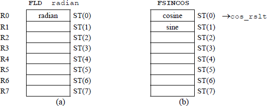
The sine and cosine, FSINCOS, instruction calculates the sine and cosine of the source operand that was previously stored in ST(0). The FSINCOS instruction stores the sine of the operand in ST(0) of the register stack, then pushes the cosine onto the stack, so that ST(0) contains the cosine and ST(1) contains the sine. The source operand is expressed in radians. If the operand is not within a specified range (–263 to +263), then bit C2 is set in the floating-point unit status word. This, however, does alter the operand in ST(0) and does not generate an exception.
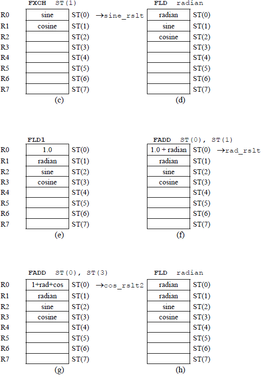
Figure 11.35 contains an assembly language module embedded in a C program that uses the trigonometric instructions FSINCOS and FPTAN to obtain the sine, cosine, and tangent of radians that are entered from the keyboard. The program also uses a new instruction exchange register contents FXCH, which exchanges the contents of register ST(0) and register ST(i). The load constant FLD1 and the add FADD instructions are also utilized in the program.

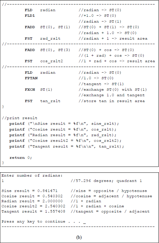
Program to illustrate utilization of the trigonometric instructions FSINCOS and FPTAN: (a) the program and (b) the outputs.
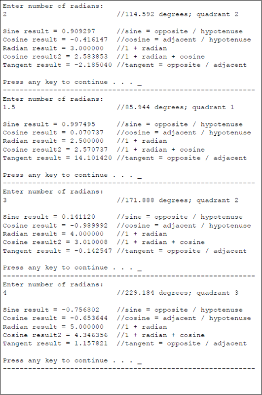
The third set of outputs in Figure 11.35(b) has an angle of 85.944 degrees, placing the angle in quadrant 1, as shown below. Since the angle is close to 90 degrees and the sine is opposite / hypotenuse, the result will be close to a value of 1. The cosine has an adjacent side that is relatively small; therefore, since the cosine is adjacent / hypotenuse, the value of the cosine is very small. In a similar manner, since the tangent is opposite / adjacent, the tangent value has a relatively large value.

The fourth set of outputs has an angle of 171.888 degrees, placing the angle in quadrant 2, as shown below. Since the angle is close to 180 degrees and the sine is opposite / hypotenuse, the result will be a small value. The cosine has an adjacent side that is negative and relatively large; therefore, since the cosine is adjacent / hypotenuse, the value of the cosine is negative and relatively large. In a similar manner, since the tangent is opposite / adjacent, the tangent value has a relatively small negative value.

The fifth set of outputs has an angle of 229.184 degrees, placing the angle in quadrant 3, as shown below. The sine has a negative opposite side; therefore, since the sine is opposite / hypotenuse, the result will be a negative value. The cosine has an adjacent side that is negative; therefore, since the cosine is adjacent / hypotenuse, the value of the cosine is also negative. Since the tangent is opposite / adjacent, the tangent value has a positive value.

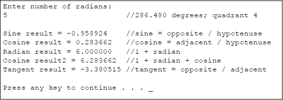
The sixth set of outputs has an angle of 286.480 degrees, placing the angle in quadrant 4, as shown below. The sine has a negative opposite side; therefore, since the sine is opposite / hypotenuse, the result will be a relatively large negative value. The cosine has an adjacent side that is positive; therefore, since the cosine is adjacent / hypotenuse, the cosine has a relatively small positive value. Since the tangent is opposite / adjacent, the tangent value has a negative value.

Figure 11.36 shows the register stack contents for different stages of program execution for Figure 11.35.
11.10 Additional Instructions
This section describes some additional floating-point instructions that perform basic arithmetic operations and have only one syntax. Most of the previous instructions in this chapter had more than one syntax. These additional instructions include the absolute value instruction: FABS; the change sign instruction: FCHS; the partial remainder instruction: FPREM1; the round to integer instruction: FRNDINT; and the square root instruction: FSQRT.
Some additional nonarithmetic instructions are also included. These include the decrement stack-top pointer instruction: FDECSTP; the free floating-point register instruction: FFREE; the increment stack-top pointer instruction: FINCSTP; and the exchange register contents instruction: FXCH. All of the above instructions are explained in the sections that follow and are listed alphabetically.
11.10.1 Absolute Value
The absolute value, FABS, instruction resets the sign bit of the operand in ST(0) of the register stack, thereby generating the absolute value of the operand. The absolute value of a number is a nonnegative number with the same numerical value without regard to the sign. Therefore, the absolute value of –12 or +12 is 12, and is written as |12| — this does not change a positive number; however, a negative number is changed to a positive number.
The absolute value of a number can also be regarded as its unit distance from the number zero. The numbers –12 and +12 are both twelve units distance from the number zero. The condition code flags that are affected in the floating-point unit status word are as follows: C1 (bit 9) is reset; C0 (bit 8), C2 (bit 10), and C3 (bit 14) are undefined. The syntax for the FABS instruction is shown below — there is no operand specified.
FABS
11.10.2 Change Sign
The change sign, FCHS, instruction complements the sign bit of the operand in ST(0) of the register stack. The instruction changes a negative value to positive value or positive value to a negative value — the absolute value of the operand does not change. The condition code flags that are affected in the floating-point unit status word are as follows: C1 (bit 9) is reset; C0 (bit 8), C2 (bit 10), and C3 (bit 14) are undefined. The syntax for the FCHS instruction is shown below — there is no operand specified.
FCHS
11.10.3 Decrement Stack-Top Pointer
The decrement stack-top pointer, FDECSTP, instruction decrements the top-of-stack (TOS) field — bits 13 through 11 — in the floating-point unit status word. The instruction subtracts one from the TOS field. For example, if the top-of-stack register was ST(0), then the FDECSTP rotates the stack by one register causing ST(7) to become the new the top-of-stack register. The contents of the stack registers and the associated tag registers are not affected.
The condition code flags that are affected in the floating-point unit status word are as follows: C1 (bit 9) is reset; C0 (bit 8), C2 (bit 10), and C3 (bit 14) are undefined. The syntax for the FDECSTP instruction is shown below — there is no operand specified.
FDECSTP
11.10.4 Free Floating-Point Register
The free floating-point register, FFREE, instruction sets the tag field associated with stack register ST(i) to indicate empty; that is, the tag field is set to 112. The contents of stack register ST(i) and the stack-top pointer, however, are not affected. The condition code flags in the floating-point unit status word are undefined. The syntax for the FFREE instruction is shown below, where ST(i) indicates a register in the register stack.
FFREE ST(i)
11.10.5 Increment Stack-Top Pointer
The increment stack-top pointer, FINCSTP, instruction increments the top-of-stack (TOS) field — bits 13 through 11 — in the floating-point unit status word. The instruction adds one to the TOS field. For example, if the top-of-stack register was ST(7), then the FINCSTP rotates the stack by one register causing ST(0) to become the new top-of-stack register. The contents of the stack registers and the associated tag registers are not affected; therefore, this instruction is not analogous to a pop operation.
The condition code flags that are affected in the floating-point unit status word are as follows: C1 (bit 9) is reset; C0 (bit 8), C2 (bit 10), and C3 (bit 14) are undefined. The syntax for the FINCSTP instruction is shown below — there is no operand specified.
FINCSTP
11.10.6 Partial Remainder
The partial remainder, FPREM1, instruction calculates the remainder that is obtained from dividing the dividend in register ST(0) by the divisor in register ST(1) and stores the result in register ST(0). The remainder is as specified in the Institute of Electrical and Electronics Engineers (IEEE) floating-point Standard 754. The remainder is also referred to as the modulus. The result that is obtained from the division process is rounded to the nearest integer.
The partial remainder is obtained by a process of repeated subtraction of no more than 63 iterations of one instruction execution. If the operation yields a result that is less than half the modulus, then the condition code flag C2 in the floating-point unit status word is reset, otherwise C2 is set. If necessary, the software can reexecute the FPREM1 instruction until the condition code flag C2 contains a value of zero. In this case, the result previously obtained and stored in ST(0) is used as the dividend. It should be noted, however, that a higher-priority interrupt can override the second iteration process. The syntax for the FPREM1 instruction is shown below — there is no operand specified.
FPREM1
11.10.7 Round to Integer
The round to integer, FRNDINT, instruction rounds the operand in ST(0) of the register stack to the nearest integer. The operand is rounded to an integer using the rounding method specified by bits 11 and 10 of the rounding control (RC) field in the floating-point control word register, reproduced in Figure 11.37. The RC field is defined as shown in Table 11.3. The rounded operand is stored in ST(0) of the register stack. A floating-point exception, indicating an indeterminate result, is produced if the source operand is not an integer. The condition code flags that are affected in the floating-point unit status word are as follows: C1 (bit 9) is reset if a stack underflow has occurred — C1 is set if the operand was rounded up; otherwise, C1 is reset; C0 (bit 8), C2 (bit 10), and C3 (bit 14) are undefined. The syntax for the FINCSTP instruction is shown below — there is no operand specified.
FRNDINT
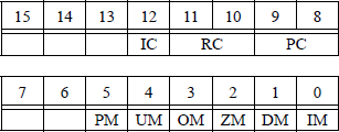
Rounding Control Field
Rounding Method |
11 |
10 |
|---|---|---|
Round to nearest (default mode) |
0 |
0 |
Round down toward minus infinity |
0 |
1 |
Round up toward positive infinity |
1 |
0 |
Round toward zero (truncate) |
1 |
1 |
11.10.8 Square Root
The square root, FSQRT, instruction calculates the square root of the source operand in ST(0) of the register stack and stores the solution in ST(0). The square root of a number a is written using the symbol , which specifies the square root of a. The square root symbol is also referred to as a radical sign. The square root of a can also be written as a05, where a ≥ 0.
There are two rules when using the square root operation. The product rule states that the square root of the product of two operands is equal to the product of the square roots of the operands, as shown below. The quotient rule states that the square root of the division of two operands is equal to the division of the square roots of the operands, also shown below.
Examples of the product rule and the quotient rule are shown below.
The condition code flags that are affected in the floating-point unit status word are as follows: C1 (bit 9) is reset if a stack underflow has occurred — C1 is set if the result was rounded up; otherwise, C1 is reset; C0 (bit 8), C2 (bit 10), and C3 (bit 14) are undefined. The syntax for the FSQRT instruction is shown below — there is no operand specified.
FSQRT
11.10.9 Exchange Register Contents
The exchange register contents, FXCH, instruction was introduced in Section 11.9.5. The instruction exchanges the contents of register ST(0) and the source register ST(i) if a source operand is specified. If there is no source operand stipulated, then the FXCH instruction exchanges the contents of ST(0) and ST(1).
Some floating-point instructions operate only on the ST(0) register. The FXCH instruction provides a convenient method of exchanging the contents of the top-of-stack register ST(0) with another register in the stack.
The condition code flags that are affected in the floating-point unit status word are as follows: C1 (bit 9) is reset if a stack underflow has occurred; otherwise, C1 is set; C0 (bit 8), C2 (bit 10), and C3 (bit 14) are undefined. The syntax for the two versions of the FXCH instruction are shown below.
FXCH ST(i) (exchange the contents of ST(0) and ST(i))
FXCH (exchange the contents of ST(0) and ST(1))
Figure 11.38 illustrates an assembly language module embedded in a C program that demonstrates the use of some of the additional instructions described in this section. The program uses the change sign FCHS instruction, the round to integer FRNDINT instruction, and the square root FSQRT instruction. A positive or negative floating-point number is entered from the keyboard and used with all three instructions.
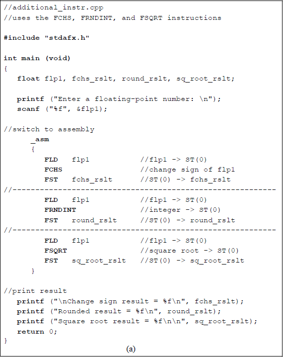
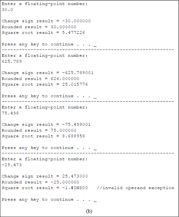
Program to illustrate using the instructions FCHS, FRNDINT, and FSQRT: (a) the program and (b) the outputs.
The first number entered is +30. The sign is changed, the number is rounded to 30.000000 using the default mode of round to nearest, and a square root of 5.477226 is generated. The second number entered is +625.789, which is rounded up to 626.000000 and yields a square root of 25.015776. The third number entered is +75.498, which is rounded down to 75.000000 and yields a square root of 8.688958. The fourth number entered is –25.473, which is rounded down to –25.000000. The square root of –25.473 is not a real number, since there is no real number with a square of –25.473. Therefore, the FSQRT instruction specifies a floating-point invalid-arithmetic-operand exception, which is indicated in the outputs as –1.#IND00 in this version of the Visual C++ software.
11.11 Problems
11.1 Convert +19.510 into a 32-bit single-precision floating-point number with a biased exponent and an implied 1.
11.2 Convert +38.12510 into a 32-bit single-precision floating-point number with a biased exponent and an implied 1.
11.3 Obtain the unbiased exponent for the floating-point number shown below in which the exponent is biased.

11.4 The floating-point number shown below has an unbiased exponent and an un-normalized fraction. Show the same floating-point number with a biased exponent and a normalized fraction in the single-precision floating-point format.

11.5 For a 23-bit fraction with an 8-bit exponent and a sign bit, determine the most negative number with the most negative unbiased exponent.
11.6 Indicate whether the following statements are true or false:
(a) Adder-based rounding requires no more time than truncation.
(b) von Neumann rounding as also referred to as chopping.
11.7 Convert the decimal number 0.08007812510 into the 64-bit double-precision floating-point number.
11.8 Round the following floating-point number to eight bits using the rounding methods shown below:
(a) Chopping
(b) Adder-based
(c) von Neumann
11.9 Convert the single-precision floating-point number shown below to an equivalent decimal number. The exponent is biased.
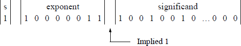
11.10 Write an assembly language module embedded in a C program that uses the add (FADDP) instruction and the add (FIADD) instruction. For the FADDP instruction, use the FADDP ST(i), ST(0) version. Enter three floating-point numbers and one integer number from the keyboard. Display the results of the program and show the register stack for each sequence of the program.
11.11 Perform an addition operation for the following floating-point numbers:
11.12 Perform an addition operation for the following floating-point numbers:
11.13 Perform an addition operation for the following floating-point numbers:
11.14 Add the two floating-point numbers shown below.
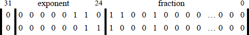
11.15 Add the two floating-point numbers shown below.
11.16 Convert the most negative 8-bit unbiased exponent to a biased exponent.
11.17 Write an assembly language module embedded in a C program that uses the sub (FSUBP) instruction and the sub (FISUB) instruction. For the FSUBP instruction, use the FSUBP ST(i), ST(0) version. Enter three floating-point numbers and one integer number from the keyboard. Enter the three separate sequences shown below. Display the results of the program and show the register stack for the third sequence of the program.
+1.2 +2.3 +3.4 +5+32.456 +45.789 +16.123 +10–237.658 +128.125 –279.463 –7511.18 Perform the following operation on the two operands: (+127) – (–77).
11.19 Perform the following operation on the two operands: (–13) – (+54).
11.20 Perform the following operation on the two operands: (–47.25) – (–18.75).
11.21 Perform the following operation on the two operands: (+36.50) – (+5.75).
11.22 Write an assembly language module embedded in a C program that uses the mul (FMULP) instruction and the mul (FIMUL) instruction. For the FMULP instruction, use the FMULP ST(i), ST(0) version. Enter three floating-point numbers and one integer number from the keyboard. Enter the three separate sequences shown below. Display the results of the program and show the register stack for the third sequence of the program.
+1.200 +2.300 +3.400 +5+32.400 +45.700 +16.100 +10–23.600 +28.500 –27.400 –1211.23 Write an assembly language module embedded in a C program to obtain the sum of cubes of n positive floating-point numbers. The sum of cubes can be represented by the following expression:
11.24 Comment on the biasing problem when the exponents are operated on during floating-point multiplication.
11.25 Write a C program to calculate the area of a flat surface using floating-point numbers. Enter three sets of floating-point numbers for the width and length.
11.26 Write an assembly language module embedded in a C program that calculates the area of a circle from a radius that is entered from the keyboard. Enter both integer radii and noninteger radii. Display the resulting areas.
11.27 How is quotient overflow determined in floating-point division? How is overflow resolved? After overflow is resolved, what is the numerical range of the dividend and divisor?
11.28 A resistor is one of four passive circuit elements: resistor, capacitor, inductor, and the recently discovered memristor. The equivalent resistance Req — specified in ohms — of resistors connected in series is the sum of the resistor values. However, the equivalent resistance of resistors connected in parallel is shown in the equation below.
The value of Req is smaller than the resistance of the smallest resistor in the parallel circuit. The circuit shown below contains three parallel resistors.

Write an assembly language module embedded in a C program that calculates the equivalent resistance of a three-resistor parallel network. Enter four sets of values for the resistors and display the equivalent resistance.
11.29 Using an assembly language module embedded in a C program, find the equivalent resistance of the circuit shown below for three sets of resistance values.
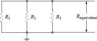
11.30 Write an assembly language module embedded in a C program to find the average of five floating-point numbers that are entered from the keyboard. Enter two sets of numbers. Display the sum and the average.
11.31 Given the program shown below, obtain the result of the program execution.
//fdivp_ex.cpp//calculate result of program
#include "stdafx.h"int main (void){float rslt;
//switch to assembly_asm{FLD1FADD ST(0), ST(0)FLDPIFMUL ST(0), ST(0)FDIVP ST(1), ST(0)FST rslt}
//print resultprintf ("\nResult = %f\n\n", rslt);
return 0;}11.32 Write an assembly language module embedded in a C program that calculates the sine, cosine, and tangent of a radian value that is entered from the keyboard. Enter radian values that correspond to the following degrees: 28.648°, 45°, 85.944°, 180°, 225°, 315°.
11.33 Write an assembly language module embedded in a C program that calculates the result of the expression shown below for different values of the floatingpoint variables flp1 and flp2.