Table of Contents for
X86 Assembly Language and C Fundamentals
 X86 Assembly Language and C Fundamentals
Published by
CRC Press, 2015
X86 Assembly Language and C Fundamentals
Published by
CRC Press, 2015
- X86 Assembly Language and C Fundamentals
- Preliminaries
- By the same Author
- X86 Assembly Language and C Fundamentals
- X86 Assembly Language and C Fundamentals
- Preface
- Chapter 1 Number Systems and Number Representations
- Chapter 2 X86 Processor Architecture
- Chapter 3 Addressing Modes
- Chapter 4 C Programming Fundamentals
- Chapter 5 Data Transfer Instructions
- Chapter 6 Branching and Looping Instructions
- Chapter 7 Stack Operations
- Chapter 8 Logical, Bit, Shift, and Rotate Instructions
- Chapter 9 Fixed-Point Arithmetic Instructions
- Chapter 10 Binary-Coded Decimal Arithmetic Instructions
- Chapter 11 Floating-Point Arithmetic Instructions
- Chapter 12 Procedures
- Chapter 13 String Instructions
- Chapter 14 Arrays
- Chapter 15 Macros
- Chapter 16 Interrupts and Input/Output Operations
- Chapter 17 Additional Programming Examples
- Appendix A ASCII Character Codes
- Appendix B Answers to Select Problems
Chapter 5
Data Transfer Instructions
This chapter presents the basic data transfer instructions as they apply to the X86 processors. Other data transfer instructions, such as instructions that pertain to stack operations and string operations, are presented in later chapters. This chapter also includes the various data types used in the X86 processors.
5.1 Data Types
The data types that are covered in this section are signed binary integers, unsigned binary integers, unpacked binary-coded decimal (BCD) integers, packed BCD integers, and floating-point numbers.
5.1.1 Signed Binary Integers
A signed integer is a binary number that is interpreted as a number in 2s complement representation, where the high-order (leftmost) bit is the sign bit. Signed integers can occupy a byte (8 bits: 7 through 0), a word (16 bits: 15 through 0), a doubleword (32 bits: 31 through 0), or a quadword (64 bits: 63 through 0), where the sign bits are bits 7, 15, 31, and 63, respectively. A sign bit of 0 indicates a positive number; a sign bit of 1 indicates a negative number. An integer has the following range:
Therefore, a signed integer byte has a range from –128 to +127, where n = 8; a signed integer word has a range from –32,768 to + 32,767, where n = 16; a signed doubleword has a range from –2,147,483,648 to +2,147,483,647, where n = 32; and a signed quadword has a range from –9.223372037 × 10¹⁸ to +9.223372037 × 10¹⁸ – 1, where n = 64.
Bytes of a number are stored in the little endian format; that is, the low-order byte is stored first at the lower address and subsequent bytes are stored in successively higher addresses in memory. Little endian can also refer to the way that the bits are ordered in a byte; for example, bits 7 through 0 in a left-to-right sequence.
The big endian format stores the high-order byte first at the lower address and subsequent bytes are stored in successively higher addresses in memory. Big endian can also refer to the way that the bits are ordered in a byte; for example, bits 0 through 7 in a left-to-right sequence. Examples of signed integers in 2s complement representation are shown in Table 5.1.
Examples of Numbers in 2s Complement Representation
Positive Numbers |
Decimal Value |
Negative Numbers |
Decimal Value |
|---|---|---|---|
0111 |
+7 |
1001 |
–7 |
0101 0110 |
+86 |
1010 1010 |
–86 |
0010 1111 0101 |
+757 |
1101 0000 1011 |
–757 |
The 2s complement is obtained by adding 1 to the 1s complement; the 1s complement is obtained by inverting all bits of the number. There is a faster way to obtain the 2s complement of a number: keep the low-order 0s and the first 1 unchanged as the number is scanned from right to left, then invert all remaining bits. An example is shown below.
5.1.2 Unsigned Binary Integers
Unsigned integers can occupy a byte (8 bits: 7 through 0), a word (16 bits: 15 through 0), a doubleword (32 bits: 31 through 0), or a quadword (64 bits: 63 through 0). An unsigned integer has the following range:
The maximum range for an unsigned byte is 28 – 1 = 255; the range for a word is 216 – 1 = 65,535; the maximum range for a doubleword is 232 – 1 = 4,294,967,295; and the maximum range for a quadword is 264 – 1 = 1.8446744072 × 10¹⁹. Examples of unsigned binary integers are shown in Table 5.2.
Examples of Unsigned Binary Integers
Unsigned Integers |
Decimal Value |
Unsigned Integers |
Decimal Value |
|---|---|---|---|
0111 |
7 |
1001 |
9 |
0101 0110 |
86 |
1010 1010 |
170 |
0010 1111 0101 |
757 |
1101 0000 1011 |
3339 |
5.1.3 Unpacked and Packed BCD Integers
Each BCD digit is an unsigned number with a range from 0 (0000) to 9 (1001); that is, the decimal number is encoded as an equivalent binary number. All numbers 10 through 15 are invalid for BCD, since a radix 10 digit contains only the decimal numbers 0 through 9.
If the BCD number is unpacked, then only the low-order bits of each byte contain a valid decimal number; the high-order bits of each byte can be an indeterminate value for addition or subtraction operations, but must be 0000 for multiplication and division operations.
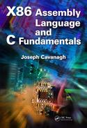
For packed BCD numbers, both the low-order and the high-order half of a byte contain valid decimal numbers. In this case, the digit in the high-order half of the byte is the most significant number. BCD digits can be packed into a format consisting of ten bytes that represent a signed decimal number, as shown in Figure 5.1. The low-order digit is D0 and the high-order digit is D17. The sign bit is bit 79, where a 0 indicates a positive number and a 1 indicates a negative number. Bits 78 through 72 are irrelevant and can be classified as don't care bits.
Positive and negative BCD numbers with the same absolute value are differentiated only by the sign bit — all decimal digits are identical for both positive and negative numbers. This is in contrast to radix 2 numbers for the diminished-radix complement and the radix complement number representations, where the bit configurations are different for positive and negative numbers. However, the 80-bit packed BCD format is similar to the sign-magnitude number representation, where only the sign bit is different.
5.1.4 Floating-Point Numbers
Floating-point numbers consist of the following three fields: a sign bit, s; an exponent, e; and a fraction, f. These parts represent a number that is obtained by multiplying the fraction, f , by a radix, r, raised to the power of the exponent, e, as shown in Equation 5.1 for the number A, where f and e are signed fixed-point numbers, and r is the radix (or base).
The exponent is also referred to as the characteristic; the fraction is also referred to as the significand or mantissa. Although the fraction can be represented in sign-magnitude, diminished-radix complement, or radix complement, the fraction is predominantly expressed in a true magnitude (unsigned) representation.
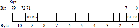
Figure 5.2 shows the format for 32-bit single-precision and 64-bit double-precision floating-point numbers. The single-precision format consists of a sign bit that indicates the sign of the number, an 8-bit signed exponent, and a 23-bit fraction. The double-precision format consists of a sign bit, an 11-bit signed exponent, and a 52-bit fraction. Fractions in the IEEE format are normalized; that is, the leftmost significand bit is a 1. Since there will always be a 1 to the immediate right of the radix point, the 1 bit is not explicitly shown — it is an implied 1.
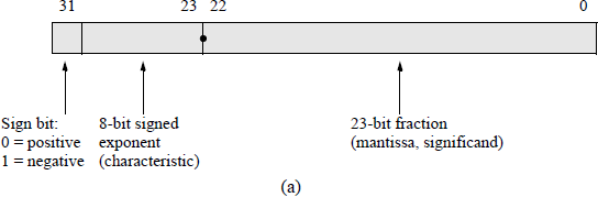
IEEE floating-point formats: (a) 32-bit single precision and (b) 64-bit double precision.
The exponents of the X86 floating-point architecture are initially unbiased numbers. An unbiased exponent can be either a positive or a negative integer. During the addition or subtraction of two floating-point numbers, the exponents are compared and the fraction with the smaller exponent is shifted right by an amount equal to the difference of the two exponents. The comparison is simplified by using biased exponents; that is, by adding a positive bias constant to each exponent during the formation of the numbers. This bias constant has a value that is equal to the most positive exponent and makes all exponents positive numbers.
For example, if the exponents are represented by n bits, then the bias is 2n − 1 – 1. For n = 4, the most positive number is 0111 (+7). Therefore, all biased exponents are of the form shown in Equation 5.2.
The advantage of using biased exponents is that they are easier to compare without having to consider the signs of the exponents. The main reason for biasing is to determine the correct alignment of the fractions by aligning the radix points, and to determine the number of bits to shift a fraction in order to obtain proper alignment. An additional advantage is that the smallest exponent contains only zeroes; therefore, the floating-point depiction of the number zero is an exponent of zero with a fraction of zero. If the biased exponent has a maximum value (255) and the fraction is nonzero, then this is interpreted as Not a Number (NaN), which is the result of zero divided by zero or the square root of – 1.
5.2 Move Instructions
This section presents some of the basic move instructions involving data transfer. These include register-to-register, immediate-data-to-register, immediate-data-to-memory, memory-to-register, and register-to-memory. Also included are moves with sign extension, moves with zero extension, and conditional moves that move data to a destination depending on the state of a flag. Data transfer instructions have the following general syntax:
MOV destination, source
The source is a general-purpose register, a segment register, immediate data, or a memory operand. The destination is a general-purpose register, a segment register, or a memory location. Debug registers can also be used as source or destination registers.
5.2.1 General Move Instructions
Examples of different forms of the MOV instruction are shown below. The general move instruction, MOV, cannot be used for memory-to-memory data transfer. The move string (MOVS) instruction is used for that operation. The MOV instruction also cannot move data from one segment register to another segment register.
Register-to-register |
MOV EAX, EBX |
|
Immediate-to-register |
MOV AX, 1234H |
|
Direct |
MOV MEM_ADDR, AX |
MEM_ADDR gives the address directly |
Register indirect |
MOV EAX, [EBP] |
[EBP] gives the address indirectly |
Indexed |
MOV AX, [DI/SI + displacement] |
Displacement may be 0 |
Based |
MOV EAX, [EBP/EBX + displacement] |
Displacement may be 0 |
Base plus index |
MOV [BP/BX + SI/DI], AX |
|
Base plus index plus displacement |
MOV [BX/BP + DI/SI + displacement], EAX |
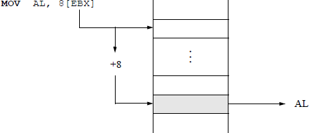
Figure 5.3 shows an example of moving a byte from a memory location, determined by the contents of register EBX, to register AL. This is an indirect addressing mode with an offset of eight. If the operand type is not obvious, then the type can be specified by either BYTE PTR, WORD PTR, DWORD PTR, for example, as shown below, which moves 0C16 to a memory location specified by the sum of the contents of registers EBX and ESI.
MOV BYTE PTR [EBX + ESI], 0CH
Structure of an X86 assembly language program Figure 5.4 illustrates a program to interchange two registers using the MOV instruction. This can be accomplished much easier by using the exchange (XCHG) instruction, which is presented in a later section. However, since this section introduces the MOV instruction, the program uses the MOV data transfer instruction.
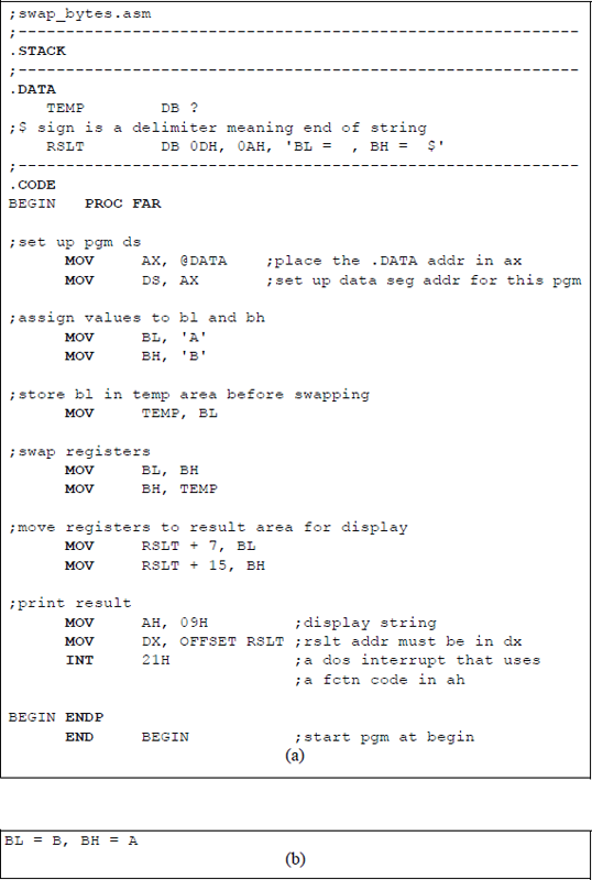
Program to illustrate interchanging the contents of two general-purpose registers BL and BH: (a) the program, and (b) the outputs.
The program is called swap_bytes and saved as swap_bytes.asm. The .STACK is a simplified segment directive that defines the stack segment; in a similar manner, the directives that define the data and code segments are labelled .DATA and .CODE, respectively. A size value can be appended to these simplified segment directives to specify their respective sizes. These directives generate the appropriate segment statements and the corresponding end segment statements. Prior to the introduction of the simplified segment directives, the segments were defined as shown below.
STSG |
SEGMENT PARA STACK ‘STACK’ |
... |
|
STSG |
ENDS |
DTSG |
SEGMENT PARA ‘DATA’ |
... |
|
DTSG |
ENDS |
CDSG BEGIN |
SEGMENT PARA ‘CODE’ |
BEGIN |
PROC FAR |
ASSUME SS:STACK, DS:DTSG, CS:CDSG |
|
... |
|
BEGIN |
ENDP |
CDSG |
ENDS |
END BEGIN |
The procedure section of the code begins with the PROC directive and ends with the end procedure (ENDP) directive. The code segment, specified by the PROC directive, contains the executable code for the program. The procedure name is BEGIN and must be distinct from any other procedure name. The operand FAR indicates the procedure entry location to begin execution of the program. The ENDP directive ends a procedure and contains the same name as the procedure; the END directive ends the program, and the operand — BEGIN in this case — contains the name of the FAR procedure where program execution is to begin.
The simplified segment directives also include predefined equates, such as @code and @data. The @data equate can be used, in conjunction with the MOV instruction, to load the offset of the data segment into register AX by the following statement:
MOV AX, @DATA
Register AX is then loaded into the data segment register DS by the following statement:
MOV DS, AX
The ASCII characters A and B are then loaded into registers BL and BH, respectively. The contents of registers BL and BH are then interchanged using the temporary storage area in the data segment declared as TEMP, which is defined as a byte location by the define byte(s) directive DB. Once the contents of the registers have been interchanged, they are moved to the RSLT area in the data segment, which is also defined as a field of individual bytes. The control character 0DH places the cursor at the left of the monitor screen; the control character 0AH specifies a line feed, which advances the output by a single line — also called a carriage return.
The control characters 0DH and 0AH occupy one byte each, where 0DH is at location 0 of the storage area designated by RSLT and 0AH is at location 1 of the storage area designated by RSLT. Register BL is moved to location RSLT + 7, which is two spaces to the right of the first equal sign — every space within the single quotation marks is one byte. Register BH is moved to location RSLT + 15, which is two spaces to the right of the second equal sign. The dollar sign ($) indicates end of string within the single quotation marks.
The statements shown below display the contents of the RSLT field. A function code of 09H (display string) is moved to register AH, which must contain the required function. The offset address of RSLT — relative to the beginning of the data segment — is moved to the required register, DX. The DOS interrupt, INT 21H, is an interrupt that uses a function code in register AH to indicate an operation to be performed — in this case the display string function.
MOV AH, 09H
MOV DX, OFFSET RSLT
INT 21H
The program of Figure 5.4 will be rewritten using an assembly language module that is linked to a C program. The revised program is shown in Figure 5.5. External names in a C program are preceded by an underscore (_) character; for example, _asm; that is, in-line assembly language is achieved by the _asm command. Since a C program is case sensitive, the assembly language section should use the same case for variable names that are common to both the C module and the assembly language module.
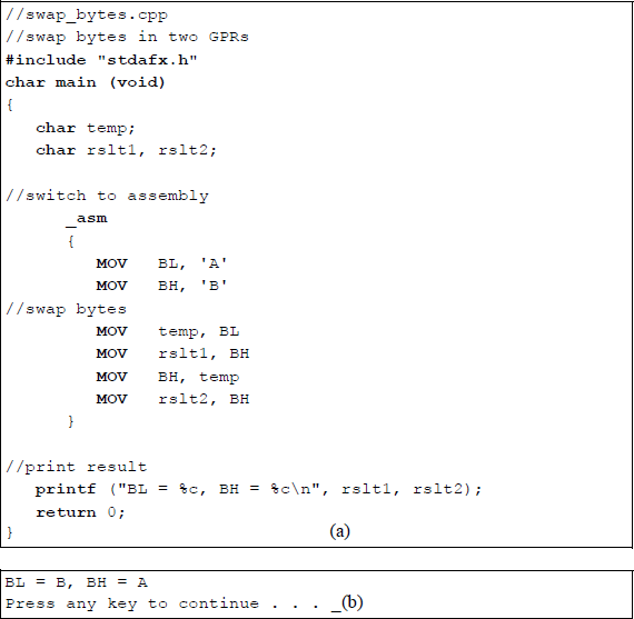
Assembly language module linked to a C module to interchange two general-purpose registers: (a) the program and (b) the outputs.
Note that there is no need to declare stack, data, or code segments in the linked program. The C module uses the stack to push and pop data as required. There is also no need to set up the data segment in the DS register. The results of the interchange program do not have to be sent to the data segment in preparation for display. The three instructions to display printing the resulting string are also not required — this is accomplished by the printf () function. Linking an assembly language to a C program makes the resulting program easier to read and understand.
5.2.2 Move with Sign/Zero Extension
The move with sign extension (MOVSX) instruction moves the source operand into a destination general-purpose register, then extends the sign bit into the high-order bits of the destination. The sign bit is extended into a 16-bit or a 32-bit destination. The MOVSX instruction is used with signed operands.
The move with zero extension (MOVZX) instruction is similar to the MOVSX instruction, except that zeroes are extended in the destination instead of the sign bit. The syntax for the MOVSX and the MOVZX instructions is shown below.
MOVSX/MOVZX register, register/memory/immediate
Figure 5.6 contains a program that illustrates both the MOVSX instruction and the MOVZX instruction. An immediate operand, 0F5H, is loaded into register AL, which is sign-extended into register EAX to yield a result of FFFFFFF5H. An immediate, 0F5H, is loaded into register BL, which is zero-extended into register EBX to yield a result of F5H (000000F5).
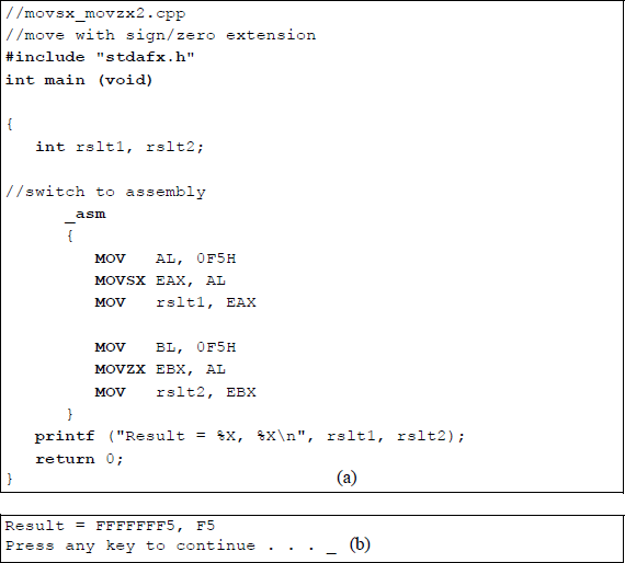
Program to illustrate the MOVSX and the MOVZX instructions: (a) the program and (b) the outputs.
5.2.3 Conditional Move
The conditional move (CMOVcc) instructions execute move operations based on the state of certain flags — condition codes (cc) — in the EFLAGS register. The condition codes are appended to the right of the CMOV instruction; for example, the instruction CMOVC will execute if the state of the carry flag is 1 (CF = 1).
The conditional move instructions move data from a source operand to a destination location; that is, from memory to a general-purpose register (GPR) or from one GPR to another GPR. Conditional moves for 8-bit registers are not supported. If the specified condition is true, then the move operation is performed. If the condition is false, then the move operation is not executed and the instruction following the CMOVcc instruction is executed. The conditional move function is similar to the if construct, in which a branch takes place if a condition is true. The conditional move instructions are shown in Table 5.3 for both unsigned and signed operations.
Conditional Move Instructions
Mnemonic |
Flags |
Description |
|---|---|---|
Unsigned |
||
CMOVA |
(CF or ZF) = 0 |
Above |
CMOVAE |
CF = 0 |
Above or equal |
CMOVNC |
CF = 0 |
No carry |
CMOVB |
CF = 1 |
Below |
CMOVC |
CF = 1 |
Carry |
CMOVBE |
(CF or ZF) = 1 |
Below or equal |
CMOVE |
ZF = 1 |
Equal |
CMOVNE |
ZF = 0 |
Not equal |
CMOVP |
PF = 1 |
Parity even |
CMOVNP |
PF = 0 |
Parity odd |
Signed |
||
CMOVGE |
(SF xor OF) = 0 |
Greater than or equal |
CMOVL |
(SF xor OF) = 1 |
Less than |
CMOVLE |
[(SF xor OF) or ZF] = 1 |
Less than or equal |
CMOVO |
OF = 1 |
Overflow |
CMOVNO |
OF = 0 |
No overflow |
CMOVS |
SF = 1 |
Sign is negative |
CMOVNS |
SF = 0 |
Sign is positive |
Compare instruction Since the conditional move instructions depend on the state of flags resulting from the execution of certain instructions, the compare instruction will be introduced at this time in order to generate flags for a conditional move instruction. One example will suffice to illustrate the operation of a conditional move instruction. The syntax for the compare instruction is shown below.
CMP first source operand, second source operand
The comparison is achieved by subtracting the second source operand from the first source operand and setting the appropriate flags. The comparison is that of the first source operand to the second source operand. The operands are unchanged after the compare operation, but the following flags are set according to the result of the compare operation: auxiliary carry or adjust flag (AF), the carry flag (CF), the overflow flag (OF), the parity flag (PF), the sign flag (SF), and the zero flag (ZF).
Figure 5.7 shows a program that illustrates the application of the conditional move instruction CMOVAE if the unsigned operand in register EAX is above or equal to the unsigned operand in register EBX. The purpose of the program is to print the larger of two operands or one operand if the two are equal. Two integers are entered by the user and stored in memory locations x and y.
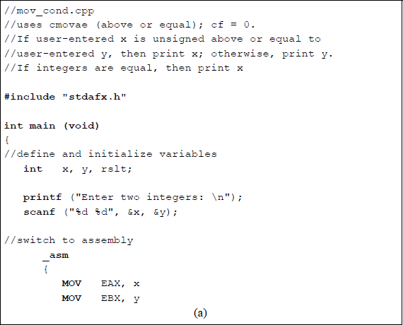
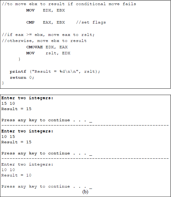
Program to illustrate the use of the conditional move instruction CMOVAE: (a) the program and (b) the outputs.
5.3 Load Effective Address
The load effective address (LEA) instruction loads the offset (effective address) of a memory address (source operand) within a memory segment and stores it in a generalpurpose register. No flags are affected by this instruction. The address calculation of the LEA instruction is similar to the calculation performed by the MOV instruction, but the address of the source operand is stored in the destination, not the contents of the source operand. The LEA instruction can also be used for unsigned integer arithmetic. The syntax for the LEA instruction is shown below.
LEA destination, source
A comparable operation to the LEA instruction is a MOV with offset operation and the equate construct that were utilized in the program of Figure 5.4, as shown below, both of which move an offset address to a destination register.
MOV DX, OFFSET RSLT
MOV AX, @DATA
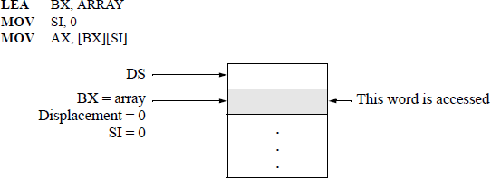
An example that illustrates one use of the LEA instruction is shown in Figure 5.8, which accesses an array element. The address of array in the data segment is loaded into register BX and register SI is cleared using the immediate addressing mode — SI will be used to index into the array. Then the word at array [0] is stored in register AX. The register addressing mode is used for the destination (AX); the base-index addressing mode is used for the source [BX][SI]. To index through the array, simply increment register SI by the appropriate amount.
5.4 Load Segment Registers
This section describes some of the instructions that load far pointers; for example, load far pointer using DS (LDS), load far pointer using SS (LSS), load far pointer using ES (LES), load far pointer using FS (LFS), and load far pointer using GS (LGS). These instructions load a far pointer (segment selector and offset), that points to a memory location, into a segment register and a general-purpose register. The 16-bit segment selector component of the far pointer is stored in the segment register specified in the operation code of the instruction; the offset is stored in the specified general-purpose register.
The syntax for a load far pointer instruction is shown below, where destination is any 16-bit or 32-bit general-purpose register and source is a 32-bit or 48-bit memory location.
Lseg destination, source
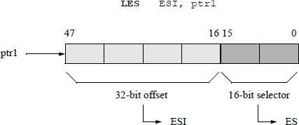
An example using the extra segment (ES) is shown in Figure 5.9 for the following instruction:
LES ESI, ptr1
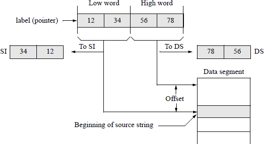
An example of a load far pointer instruction using the data segment (DS) register and the source index (SI) register is shown in Figure 5.10. This example sets SI for string operations; SI contains the offset of the string.
LDS SI, label
5.5 Exchange Instructions
This section presents four different interchange-type instructions. One instruction exchanges the contents of a register — or memory location — with a register (XCHG); another reverses the order of bytes in a register (BSWAP); another exchanges the contents of two operands, then stores the sum in the destination (XADD); and another compares the contents of a specific register with the contents of a register — or memory location — then performs a move operation depending on the results of the comparison (CMPXCHG).
5.5.1 Exchange
The exchange (XCHG) instruction exchanges the contents of the source and destination operands. The operands can be two general-purpose registers (GPRs) or a GPR and a memory location. This is a simpler and more expeditious method of exchanging two operands than the method using the MOV instruction of Figure 5.4 — no temporary storage location is required to hold one of the operands.
When an XCHG instruction is executed, the LOCK prefix asserts the processor's LOCK# signal. In a multiprocessor environment, the LOCK prefix ensures that the processor maintains uninterrupted use of any shared memory. This prevents other threads from accessing the memory location while the instruction is executing. The LOCK prefix is applicable only to certain instructions and is asserted for the duration of the instruction that follows the LOCK prefix; that is, the LOCK prefix prepends the instruction to which it applies.
The syntax for the XCHG instruction is shown below, where the source and destination operands can be a register or a memory location, but cannot both be memory locations. The flags are not affected by the XCHG instruction.
XCHG destination, source
XCHG register/memory, register/memory
There are several versions of assemblers for use with X86 assembly language programming. The various assemblers include the following: Microsoft Macro-Assembler (MASM), Netwide Assembler (NASM), Lazy Assembler (LZASM), NewBasic Assembler (NBASM), Flat Assembler (FASM), CodeX Assembler, and TMA Macro Assembler, among others. This book uses a version of a flat assembler.
Figure 5.11 illustrates the parameter list array in the data segment that is used to store the keyboard input data. Figure 5.12 shows an example of the XCHG instruction to swap two registers. The name PARLST (parameter list) in the data segment is the name of a one-dimensional array that is labelled as a byte array and accepts input data from the keyboard. The first element of the array, PARLST [0], is called MAXLEN, which defines the maximum number of input characters — in this example, five is the maximum number of allowable characters.

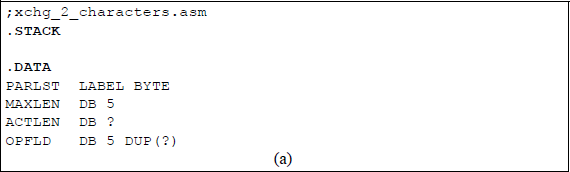
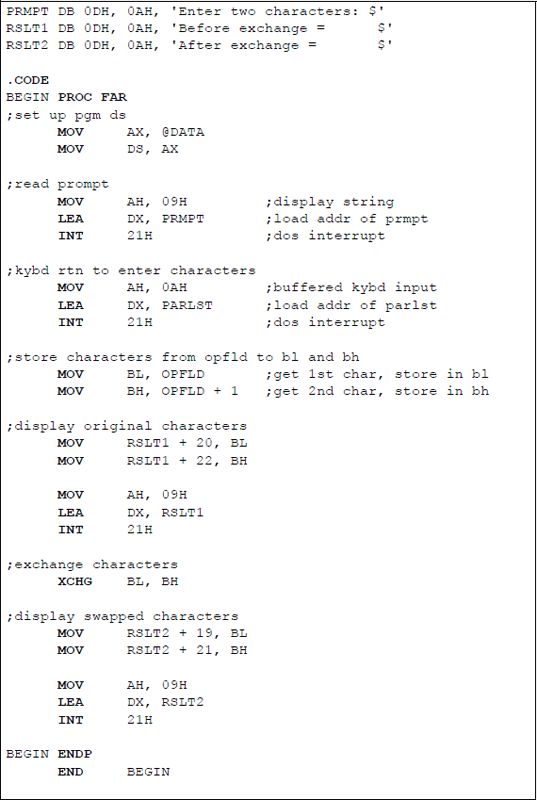
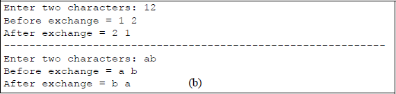
Example to illustrate the use of the XCHG instruction: (a) the program and (b) the outputs.
The second array element, PARLST [1], is called ACTLEN, which stores the actual number of characters entered from the keyboard. The third element of the array, PARLST [2], contains the beginning of the operand field (OPFLD) where the operands from the keyboard are stored — the last byte in the OPFLD is the Enter (carriage return) character (↵).
Following the PARLST array in the data segment is a prompt (PRMPT) for the user to enter two characters. The 0DH byte is the carriage return character; the 0AH byte is the line feed character. A string to be displayed is enclosed in single quotation marks and is terminated by a dollar sign ($), which indicates end of string. The code to display the prompt is shown below. The INT 21H is an operating system interrupt that uses a function code in register AH to specify an operation to be performed. The function code 09H is a display string routine. The address of the string to be displayed (PRMPT) is placed in register DX by the LEA instruction.
MOV AH, 09H
LEA DX, PRMPT
INT 21H
The code to receive the keyboard input data is similar, except that the function code 0AH is used to indicate that the function is a buffered keyboard input. The data are stored in the PARLST one-dimensional array beginning at location OPFLD.
The label RSLT1 displays the characters before they are exchanged. The first byte (B) of the string is location RSLT1 [2]. Each character, including spaces, is one byte; therefore, the first character entered from the keyboard is placed at location RSLT1 [20] — one space past the equal sign. In a similar manner, after the characters are exchanged, they are placed in the RSLT2 area of the data segment. The ENDP directive indicates the end of the procedure named BEGIN. The END directive indicates the end of the program.
Figure 5.13 shows a similar program in which two integers are exchanged by an X86 assembly language program that is linked to a C program. Note the simplicity of the code — there is no need to specify a stack segment, a data segment, or a code segment. There is also no need to display the original integers — they are automatically displayed by the printf () function when they are entered. Two integers are entered by the user and are stored in locations x and y. The integers are then moved to registers EAX and EBX, where they are exchanged by the instruction XCHG EAX, EBX, then displayed by the printf () function; thus, there is also no need to precisely position the results of the operation for display.
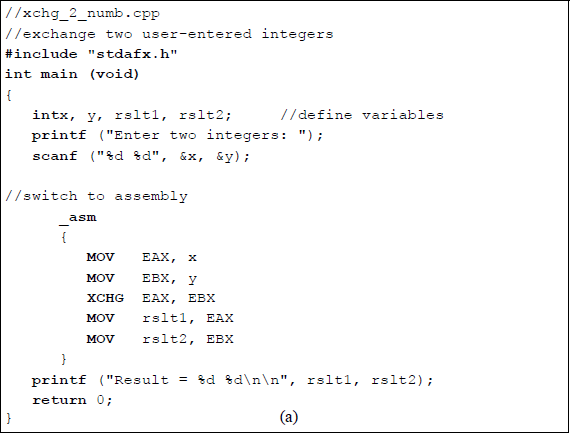
Exchange two integers by linking as X86 assembly language program to a C program: (a) the program and (b) the outputs.
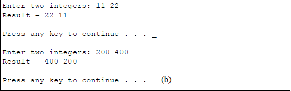
5.5.2 Byte Swap
The byte swap (BSWAP) instruction reverses the order of the bytes in a 32-bit or a 64bit general-purpose register. For a 32-bit register, bit positions 0 through 7 are swapped with bit positions 24 through 31 and bit positions 8 through 15 are swapped with bit positions 16 through 23, as shown in Figure 5.14. This effectively converts a little endian format to a big endian format and a big endian format to a little endian format. The syntax for the byte swap instruction is shown below, where the destination register is a 32-bit or a 64-bit general-purpose register.
BSWAP destination register
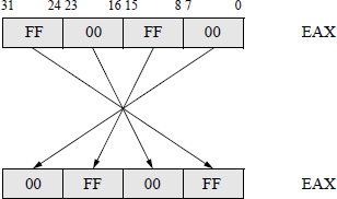
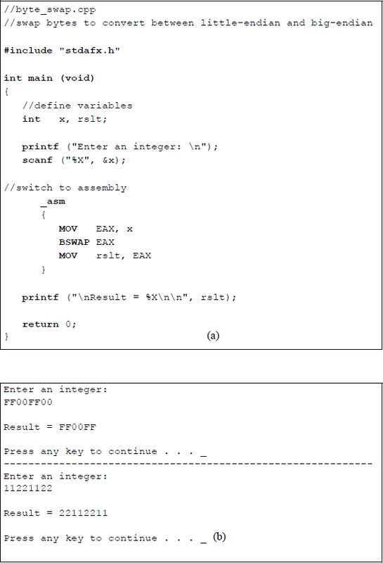
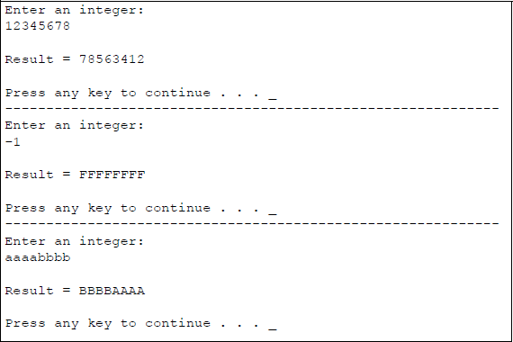
The byte swap instruction is not defined for 16-bit registers; to swap bytes in a 16bit register, the XCHG instruction should be used. Figure 5.15 shows a program to illustrate the BSWAP instruction for a 32-bit general-purpose register, EAX. A user-entered integer is stored in location x as uppercase hexadecimal characters. The character is then moved to register EAX where the byte swap operation takes place. The result of the operation is then moved to location rslt to be displayed.
5.5.3 Exchange and Add
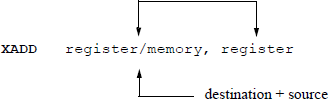
The exchange and add (XADD) instruction exchanges the destination operand with the source operand, then stores the sum of the two operands in the destination location. The destination operand can be in a register or memory location; the source operand is in a general-purpose register. The syntax for the XADD instruction is shown below.
The register and memory operands can be 8-bit, 16-bit, 32-bit, or 64-bit operands. The XADD instruction can also utilize the LOCK prefix to ensure that the processor maintains uninterrupted use of any shared memory until the instruction has completed execution. Figure 5.16 shows a linked C and assembly language program that demonstrates the use of the XADD instruction using the EAX and EBX general-purpose registers.
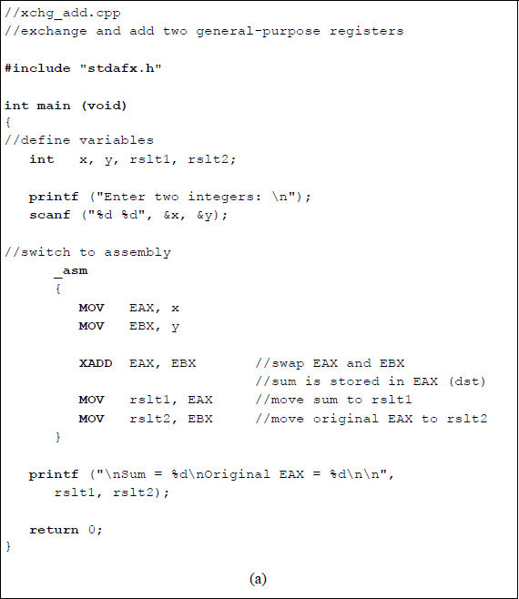
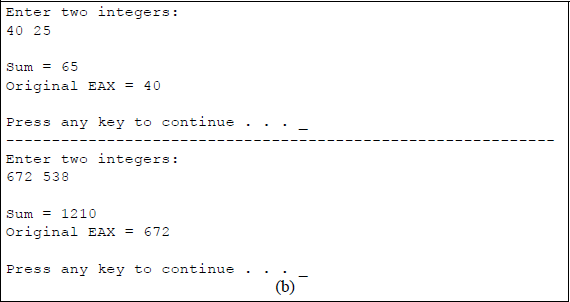
A linked C and assembly program that demonstrates the use of the exchange and add (XADD) instruction using the EAX and EBX general-purpose registers: (a) the program and (b) the outputs.
Two integers are entered from the keyboard and stored in locations x and y, then moved to registers EAX and EBX, respectively. The XADD instruction is then executed which swaps the contents of the two registers and obtains their sum, which is stored in the destination register EAX. The program then moves the sum to location rslt1 and the original value of register EAX to rslt2. The corresponding results are then displayed. The flags in the EFLAGS register specify the result of the addition operation.
5.5.4 Compare and Exchange
Since the primary focus of this book is to present the code segment for X86 assembly language programming, it is of lesser importance to include the stack segment and the data segment in each program. Therefore, most of the programs will be structured as an assembly language module embedded in a C program. Also, the methods to obtain keyboard input data and to display the results of an assembly language program are simpler when using the C functions of scanf () and printf ().
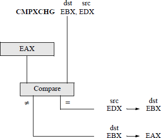
This section presents the compare and exchange (CMPXCHG) instruction, which compares the value in the accumulator with the value in the destination operand. If the two operands are equal, then the source operand is stored in the destination location — a register or a memory location. If the two operands are not equal, then the destination operand is stored in the accumulator. The syntax for the CMPXCHG instruction is shown below.
CMPXCHG register/memory, register
The flags in the EFLAGS register indicate the result of the operation that is obtained after subtracting the destination operand from the contents of the accumulator. The CMPXCHG instruction can be combined with the processor's LOCK prefix. In a multiprocessor environment, the LOCK prefix ensures that the processor maintains exclusive use of shared memory, thus preventing other threads from accessing the memory location while the instruction is executing. This is referred to as an atomic operation, which is used to maintain synchronization and to avoid race conditions in a multiprocessor environment. Many instructions, such as the XCHG and XADD instructions, among others, always assert the LOCK# signal whether the LOCK prefix is present or not.
The diagram shown in Figure 5.17 graphically portrays the operation of the CMPXCHG instruction using EAX as the accumulator register, EBX as the destination register, and EDX as the source register. Figure 5.18 shows a program to illustrate the use of the instruction CMPXCHG using the registers shown in Figure 5.17.
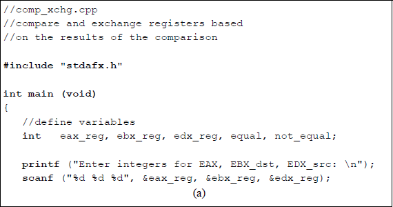
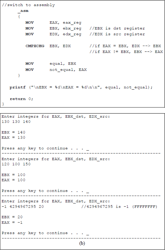
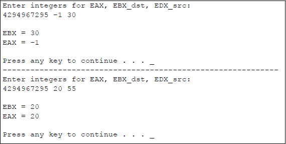
Program to illustrate the use of the CMPXCHG instruction: (a) the program and (b) the outputs.
5.6 Translate
The translate (XLAT or XLATB) instructions use the contents of register AL as an index into a translation table in memory that contains the translated byte of data. The data at the memory location addressed by the index is then stored in AL. The index value in register AL is treated as an unsigned integer, which is added to the contents of the base register (E)BX to obtain the base address of the translation table in the data segment, as shown in Figure 5.19 using register BX as the base register.
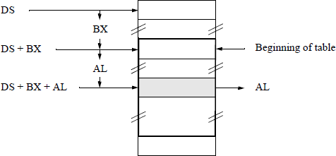
The XLAT instruction permits the base address of the translation table to be specified with a symbol. The base address must be explicitly stored in registers DS:(E)BX before execution of the XLAT instruction. The XLATB instruction, however, assumes that the DS:(E)BX registers contain the base address of the translation table. This is often referred to as the short form of the translation instruction. The translation instructions are often used to translate from one code to another code; for example, from the ASCII code to the EBCDIC code that is used in the IBM mainframes.
An assembly language program will be coded to translate a 4-bit binary number to the corresponding 4-bit Gray code number using the XLATB instruction. The binary code and Gray code for four bits are shown in Table 5.4.
Binary 8421 Code and the Gray Code
Binary Code |
Gray Code |
||||||||
|---|---|---|---|---|---|---|---|---|---|
Row |
b3 |
b2 |
b1 |
b0 |
g3 |
g2 |
g1 |
g0 |
|
0 |
0 |
0 |
0 |
0 |
0 |
0 |
0 |
0 |
|
1 |
0 |
0 |
0 |
1 |
0 |
0 |
0 |
1 |
|
2 |
0 |
0 |
1 |
0 |
0 |
0 |
1 |
1 |
← g0 is reflected |
3 |
0 |
0 |
1 |
1 |
0 |
0 |
1 |
0 |
|
4 |
0 |
1 |
0 |
0 |
0 |
1 |
1 |
0 |
← g1 and g0 are reflected |
5 |
0 |
1 |
0 |
1 |
0 |
1 |
1 |
1 |
|
6 |
0 |
1 |
1 |
0 |
0 |
1 |
0 |
1 |
|
7 |
0 |
1 |
1 |
1 |
0 |
1 |
0 |
0 |
|
8 |
1 |
0 |
0 |
0 |
1 |
1 |
0 |
0 |
← g2, g1, and g0 are reflected |
9 |
1 |
0 |
0 |
1 |
1 |
1 |
0 |
1 |
|
10 |
1 |
0 |
1 |
0 |
1 |
1 |
1 |
1 |
|
11 |
1 |
0 |
1 |
1 |
1 |
1 |
1 |
0 |
|
12 |
1 |
1 |
0 |
0 |
1 |
0 |
1 |
0 |
|
13 |
1 |
1 |
0 |
1 |
1 |
0 |
1 |
1 |
|
14 |
1 |
1 |
1 |
0 |
1 |
0 |
0 |
1 |
|
15 |
1 |
1 |
1 |
1 |
1 |
0 |
0 |
0 |
|
The Gray code is an nonweighted code that has the characteristic whereby only one bit changes between adjacent code words. The Gray code belongs to a class of cyclic codes called reflective codes, as can be seen in Table 5.4. Notice in the first four rows, that g0 reflects across the reflecting axis; that is, g0 in rows 2 and 3 is the mirror image of g0 in rows 0 and 1. In the same manner, g1 and g0 reflect across the reflecting axis drawn under row 3. Thus, rows 4 through 7 reflect the state of rows 0 through 3 for g1 and g0. The same is true for g2, g1, and g0 relative to rows 8 through 15 and rows 0 through 7.
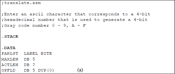
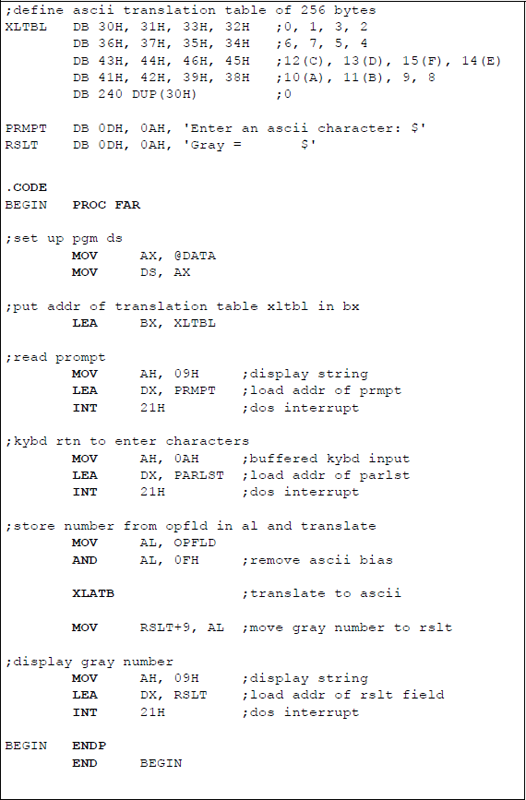
Since the data in the translation table is one byte, the translation table is 28 = 256 bytes in length. Figure 5.20 shows an assembly language program to demonstrate the use of the XLATB instruction, which is a one-byte instruction. This program translates a binary code of four bits to the corresponding Gray code of four bits. An ASCII character is entered that corresponds to a 4-bit binary number, in the form of a hexadecimal digit, that is used to generate a 4-bit Gray code number 0 – 9, A – F. This is only one of several methods to perform the conversion. In a later chapter, a different method will be used that is more appropriate — 1s and 0s are entered as the binary number — but that method requires the use of instructions that have not yet been discussed. This method achieves the translation using the binary-to-Gray conversion algorithm.
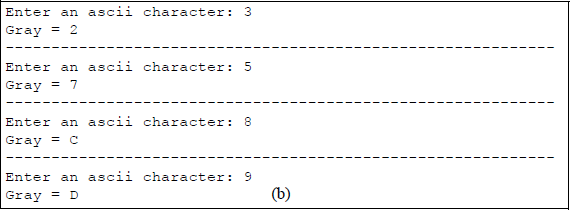
Program to illustrate using the XLATB instruction to convert binary code to Gray code: (a) the program and (b) the outputs.
In Figure 5.20, the translation table, XLTBL, is defined where the first 16 bytes represent the Gray code numbers that were translated from the corresponding binary numbers. The remaining 240 bytes are declared as zeroes (ASCII 30H). The usual sequence of instructions is utilized: set up the program's data segment; load the address of the translation table into register BX; read the prompt; and enter the keyboard character.
Then the character that was entered from the keyboard and placed into the operand field (OPFLD) is moved to register AL as the index, where the ASCII bias is removed. For example, if the number 5 (0101) is entered, then this is represented as 35H in ASCII — 0011 0101 in binary — but the binary number 0000 0101 is required as the index. Therefore, the high-order four bits — the ASCII bias — must be removed. This is accomplished by ANDing the 0011 0101 with 0000 1111 to produce 0000 0101, the required number to access the sixth entry in the translation table to yield the corresponding Gray code number of 0000 0111. This number can then be printed on the monitor screen as a 7, which is 37H in ASCII. The AND instruction is presented in more detail in Chapter 9, together with the other logic operations.
The translation instruction, XLATB, is then executed, which places the translated data in register AL. The contents of AL are then moved to the result area (RSLT) where the Gray code is displayed by the DOS interrupt INT 21H.
The conversion from binary to ASCII can also be accomplished by a simple C program, as shown in Figure 5.21. An integer array, labelled gray, is a 256-byte array in which the first 16 bytes contain the Gray code for the equivalent binary code — the remaining 240 bytes are initialized to zero by the C compiler.
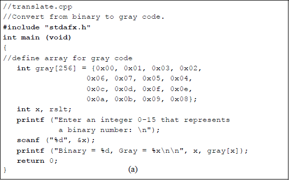
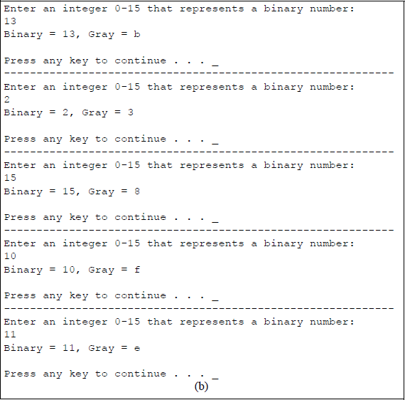
A user-entered integer specifies the decimal equivalent of a binary number that is stored in location x. For example, if 1110 (1011) is entered, then the corresponding Gray code is E (1110). The Gray code is printed as specified by the gray[x] entry in the array gray[256].
5.7 Conversion Instructions
This section presents the following conversion instructions: convert byte to word (CBW), convert word to doubleword (CWD), convert word to doubleword extended (CWDE), and convert doubleword to quadword (CDQ). Each of these conversion instructions requires no operands and they double the size of the implied source register by extending the sign bit into the implied destination extension register. The flags are not affected by any of these instructions.
These are similar in function to the two move instructions discussed in Section 5.2.2. The move with sign extension (MOVSX) moves the source operand into a destination general-purpose register, then extends the sign bit into the high-order bits of the destination. The move with zero extension (MOVZX) instruction extends zeroes into the destination. Figure 5.22 shows the four conversion instructions together with a graphical illustration of their function.
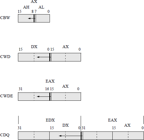
Convert byte to word (CBW) The CBW instruction copies the sign bit (bit 7) of register AL into every bit position of register AH, effectively increasing the size of the implied source register, AL, from a byte to a word. The CBW instruction is designed for use when the operand-size attribute is 16 bits. During a division operation, a 2n-bit dividend is divided by an n-bit divisor; therefore, the CBW instruction can be used to produce a word dividend from a byte dividend prior to a byte division operation.
Convert word to doubleword (CWD) The CWD instruction copies the sign bit (bit 15) of register AX into every bit position of register DX, thereby doubling the size of the implied source operand register. Thus, the CWD instruction uses the DX:AX register pair as the destination operand. During a division operation, the CWD instruction can be used to produce a doubleword dividend from a word dividend before the divide operation commences.
Convert word to doubleword extended (CWDE) The CWDE instruction copies the sign bit (bit 15) of register AX into the high-order 16 bits of register EAX. The CWDE instruction is used when the operand-size attribute is 32 bits. The CWDE instruction differs from the CWD instruction, in that the CWDE instruction uses register EAX as the destination register; whereas, the CWD instruction extends the sign bit in register AX throughout register DX.
Convert doubleword to quadword (CDQ) The CDQ instruction copies the sign bit (bit 31) of register EAX into every bit position of register EDX, thereby doubling the size of the implied source operand register. Thus, the CDQ instruction uses the EDX:EAX register pair as the destination operand. The CDQ instruction can be used to produce a quadword dividend from a doubleword dividend before the division operation begins. Figure 5.23 shows an assembly language module embedded in a C program that illustrates the use of the CDQ instruction. An integer is entered from the keyboard and stored in location eax_reg, then copied to general-purpose register EAX. The conversion instruction CDQ is then executed and the results are displayed by the printf () function.
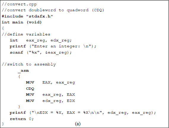
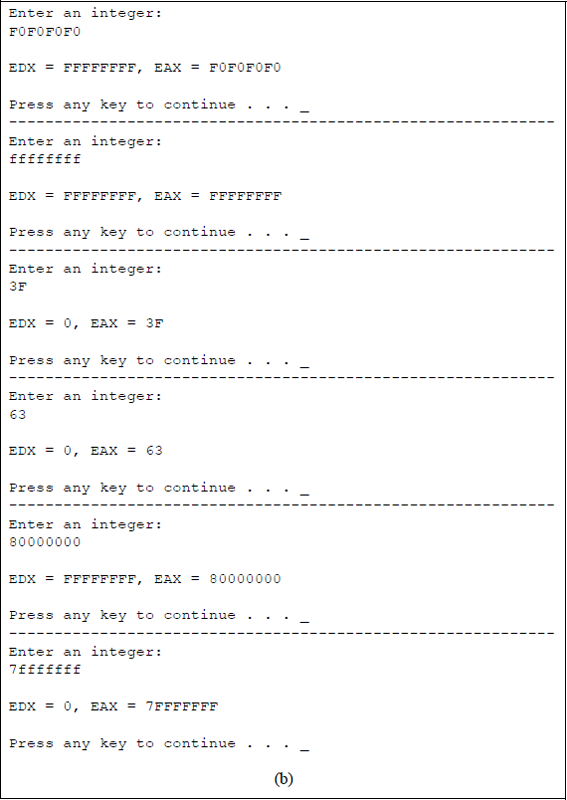
Program to illustrate using the conversion instruction CDQ: (a) the program and (b) the outputs.
5.8 Problems
5.1 Let A and B be two binary integers in 2s complement representation, where A = 1011 0001 and B = 1110 0100. A′ and B′ are the 1s complement of A and B, respectively. Determine the following: A′ + 1 and B′ + 1.
5.2 The 1s complement (diminished-radix complement) can be obtained by subtracting all bits of the number from 1. The 2s complement (radix complement) is obtained by adding 1 to the 1s complement, as shown below for the binary number 1110 (–2), which is in 2s complement representation.
The following number is in radix complement representation for radix 16: F8B616. Perform the operation of radix complementation (16s complementation) on the number.
5.3 The sign-magnitude notation for a positive number is represented by the equation shown below, where the sign bit of 0 indicates a positive number.
The sign-magnitude notation for a negative number is represented by the equation shown below, where the sign bit is the radix minus 1. In sign-magnitude notation, the positive version differs from the negative version only in the sign digit position. The magnitude portion an–2 an–3 ... a1a0 is identical for both positive and negative numbers of the same absolute value.
The numbers shown below are in sign-magnitude representation for radix 2. Convert the numbers to 2s complement representation with the same numerical value using eight bits.
Sign-magnitude
2s Complement
(a)
0111 1111
(b)
1111 1111
(c)
0000 1111
(d)
1000 1111
(e)
1001 0000
5.4 Convert the positive 2s complement numbers shown below to negative numbers in 2s complement representation.
5.5 Determine the bias constant for an 8-bit floating-point exponent.
5.6 Write a program using C and assembly language that shows the application of the conditional move below or equal (CMOVBE) instruction for unsigned operands.
5.7 Write a program using C and assembly language that shows the application of the conditional move greater than or equal (CMOVGE) instruction for signed operands.
5.8 Write a program using C and assembly language that shows the application of the conditional move less than or equal (CMOVLE) instruction for signed operands.
5.9 Write a program using C and assembly language that shows the application of the conditional move no parity (CMOVNP) instruction for unsigned operands. The compare instruction subtracts the second source operand from the first source operand and sets the parity flag accordingly. If the low-order byte of the difference contains an odd number of 1s, then the parity flag equals zero; otherwise, the parity flag equals one.
5.10 Write a program using C and assembly language that shows the application of the conditional move sign (CMOVS) instruction for signed operands. The compare instruction subtracts the second source operand from the first source operand and the state of the sign flag is set to either 0 or 1, depending on the sign of the result. If the sign of the difference is negative (SF = 1), then the move operation is executed.
5.11 Use the exchange and add (XADD) instruction for two 32-bit user-entered hexadecimal integers. Display the results in lowercase hexadecimal.
5.12 Use the compare and exchange (CMPXCHG) instruction for three 32-bit user-entered hexadecimal integers. Display the results in lowercase hexadecimal.
5.13 Write a C program to convert a decimal number to the square of the number. Use an array to translate the decimal numbers 0 through 15 to their corresponding squares.