Table of Contents for
X86 Assembly Language and C Fundamentals
 X86 Assembly Language and C Fundamentals
Published by
CRC Press, 2015
X86 Assembly Language and C Fundamentals
Published by
CRC Press, 2015
- X86 Assembly Language and C Fundamentals
- Preliminaries
- By the same Author
- X86 Assembly Language and C Fundamentals
- X86 Assembly Language and C Fundamentals
- Preface
- Chapter 1 Number Systems and Number Representations
- Chapter 2 X86 Processor Architecture
- Chapter 3 Addressing Modes
- Chapter 4 C Programming Fundamentals
- Chapter 5 Data Transfer Instructions
- Chapter 6 Branching and Looping Instructions
- Chapter 7 Stack Operations
- Chapter 8 Logical, Bit, Shift, and Rotate Instructions
- Chapter 9 Fixed-Point Arithmetic Instructions
- Chapter 10 Binary-Coded Decimal Arithmetic Instructions
- Chapter 11 Floating-Point Arithmetic Instructions
- Chapter 12 Procedures
- Chapter 13 String Instructions
- Chapter 14 Arrays
- Chapter 15 Macros
- Chapter 16 Interrupts and Input/Output Operations
- Chapter 17 Additional Programming Examples
- Appendix A ASCII Character Codes
- Appendix B Answers to Select Problems
Chapter 6
Branching and Looping Instructions
This chapter describes program transfer control using branching and looping instructions. These instructions transfer control to a section of the program that does not immediately follow the current instruction. The transfer may be a backward transfer to a section of code that was previously executed or a forward transfer to a section of code that follows the current instruction.
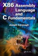
There are three basic types of addresses (or pointers) provided by the assembler: a short address, a near address, and a far address. A short address (or short jump) transfers control to an address that is located –128 to +127 bytes from the current location (the current EIP value). A near address (or near jump) transfers control to an address within the current code segment that has a 16-bit or 32-bit offset — also referred to as an effective address. A far address (or far jump) transfers control to an address obtained from a 16-bit segment selector and a 16-bit or 32-bit offset. Far addresses (pointers) are used to transfer control to an address outside the current code segment. Near and far pointers are shown in Figure 6.1 for non-64-bit mode.
6.1 Branching Instructions
There are various types of branch instructions, including unconditional jumps, conditional jumps, and if structures. A jump instruction alters the sequence of flow through the program by branching — or jumping — to another point in the program. A branch can be executed or not executed depending on certain conditions, such as the state of flags in the EFLAGS register. If a branch is not taken, then the program executes the instruction that follows the branch instruction. If a branch is taken, then the program jumps to a new location in the program; that is, an instruction in a different location in memory.
Branch instructions are relative to the current instruction pointer (E)IP, which points to a particular instruction in the current code segment. The combination of the segment selector and the offset is the logical address of the next instruction to be executed. Branching is facilitated by means of a branch target buffer (BTB), which is a set-associative cache that is used to predict whether a branch will be performed — refer to Chapter 2 for a review of a set-associative cache. The BTB cache entries contain the address of the branch instruction in conjunction with the branch target address. The cache contains information regarding the branch history; that is, about recently encountered branch instructions.
When a branch instruction is encountered, the BTB is examined to determine if there is an entry for the branch instruction. If there is a miss, the branch is assumed to have not been executed; if there is a hit, the branch history is checked to determine if the branch should be taken. If the branch is predicted to have failed, then program execution continues with the next sequential instruction; otherwise, a branch to the target address is performed.
6.1.1 Unconditional Jump Instruction
The unconditional jump (JMP) instruction advances the (E)IP register forward or backward a specific number of instructions. It transfers control to a destination address and provides no return address. The destination address may be in the current code segment or outside the current segment and can be a relative address or an absolute address. If the transfer is to an address within the current code segment, then this is referred to as an intrasegment transfer, which may be direct or indirect. If the transfer is to an address outside the current code segment, then this is referred to as an intersegment transfer, which may be direct or indirect.
A relative address is obtained by adding a signed offset to the (E)IP register to generate a near pointer. The signed offset (or displacement) allows for either a forward jump or a backward jump. An absolute address is measured from the base of the current code segment and is stored in the (E)IP register as an offset in the code segment (near pointer), or the address is obtained using a segment selector stored in the CS register and an offset in the (E)IP register. The syntax for the JMP instruction is shown below.
JMP short/near/far address
A short jump is an intrasegment jump and has a 1-byte displacement that is added to the RIP register then sign-extended to 64 bits — the EIP register becomes the RIP register in 64-bit mode. The jump range for a 1-byte displacement is –128 to +127 from the current value of the (E)IP register. When a short jump is specified as a relative offset, this is represented by label and is encoded as a signed displacement that is relative to the current value of the (E)IP register.
A near jump is an intrasegment jump whose branch target address is either an absolute offset or a relative offset that is relative to the next instruction. In 64-bit mode, the relative near jump has a displacement of 32 bits that is added to the RIP register then sign-extended to 64 bits.
A far jump is an intersegment jump. The branch target address can specify an absolute address directly by using a pointer in the instruction, where the segment and offset are encoded in the instruction; or the branch target address can specify an indirect address from a memory location, where the low-order part of the memory location is placed in the (E)IP register and the high-order part of the memory location is placed in the CS register. All JMP instructions also clear the instruction prefetch queue.
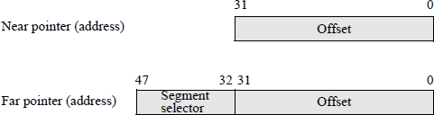
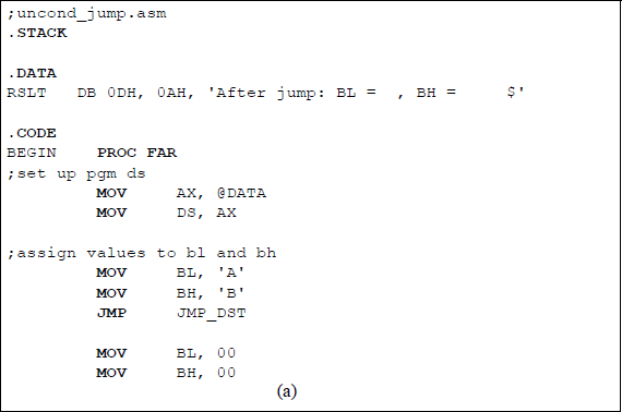
Figure 6.2 shows a simple assembly language program that illustrates the JMP instruction. Registers BL and BH are assigned the values of A (41H) and B (42H), respectively. Before they can be changed to AL = BL = 00 by two MOV instructions, however, a jump instruction is executed to a location in the program that moves the original contents of the two registers to the RSLT area in the data segment to be displayed.
The main reason for this program is to introduce the operation codes for the JMP instruction together with the addressing mode byte and the branch target address for a jump instruction. There are four different 1-byte operation codes for a jump instruction, depending on whether it is a short jump, a near jump, or a far jump. The operation code for an intrasegment short jump is EBH (1110 1011). The operation codes for near jumps are E9H (1110 1001) and FFH (1111 1111). The E9H operation code is intrasegment direct and can be used with a displacement that is relative to the next instruction or with the RIP register with a 32-bit displacement sign extended to 64 bits. The FFH operation code is used with indirect addressing that is either intrasegment indirect or intersegment indirect.
The operation codes for a far jump are EAH (1110 1010) or FFH (1111 1111). The EAH operation code is used for an intersegment direct operation with an absolute address given the instruction. The FFH operation code is used with absolute addressing obtained indirectly from memory, where the memory location is partitioned into two parts: one for the CS register and one for the (E)IP register.
Table 6.1 shows the machine codes for the instruction segment shown below. The jump instruction in this program is a short intrasegment direct jump with a 1-byte displacement. Therefore, the jump range is from +127 bytes to –128 bytes from the updated (E)IP register.
...
JMP JMP_DST MOV BL, 00
MOV BH, 00;move bl and bh to rslt area in ds
JMP_DST: MOV RSLT + 19, BL
...
Machine Codes for the Program Segment of Figure 6.2
Physical Address |
Machine Code |
Symbolic Instruction |
Machine Instruction |
|
|---|---|---|---|---|
... |
||||
07239 |
EB |
JMP JMP_DST |
JMP 0FH |
|
0723A |
04 |
|||
0723B |
B3 |
MOV BL, 00 |
MOV BL, 00H |
|
0723C |
00 |
|||
0723D |
B7 |
MOV BH, 00 |
MOV BH, 00H |
|
0723E |
00 |
|||
0723F |
88 |
JMP_DST: |
MOV RSLT + 19, BL |
MOV [00013H], BL |
07240 |
1E |
|||
07241 |
13 |
|||
07242 |
00 |
|||
... |
||||
Assume that the CS register is 0723H and that the IP register is 0009H. Then the real (physical) address is obtained as shown below, where the CS register is shifted left four bits and the IP register is right-aligned for the addition operation.
The machine code for the jump instruction is EBH, which is an intrasegment direct short jump. The second byte is a displacement of 04H, which results in a jump of four bytes past the updated IP register — the updated IP register is 000BH. The resulting target address for the jump instruction is
CS × 16 (07230H) + right-aligned IP (0000BH) + 04H = 0723FH
This is shown in the machine jump instruction as 0FH, which represents the IP register contents of the jump target address — 0723FH.
The instruction format for the move instruction that moves register BL to the rslt area (MOV RSLT + 19, BL) is as follows:
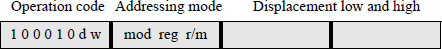
If d = 0 in the operation code, then the source operand is a register; if d = 1, then the destination operand is a register. If w = 0, then the width is a byte; otherwise, the width is a word. For the move instruction, the source is register BL; therefore, d = 0. Since register BL is a byte operand, therefore, w = 0, resulting in an operation code of 1000 1000 (88H).
An addressing mode byte may also be used with an instruction. When used, it is contiguous to the operation code and consists of three fields: a 2-bit mod field that is used to differentiate between register addressing and memory addressing and is defined in Table 6.2; a 3-bit reg field that determines the size of the operands and is shown in Table 6.3; and a 3-bit r/m (register/memory) field that is used in conjunction with the mod field to determine the addressing mode and is shown in Table 6.4.
Definition of the mod Bits
mod |
Definition |
|---|---|
0 0 |
No displacement unless r/m = 110, then there is displacement high and low |
0 1 |
There is displacement (offset) low sign-extended to 16 bits |
1 0 |
There is displacement (offset) high and low |
1 1 |
The r/m field specifies a register |
Definition of the reg Bits
w = 0 |
w = 1 |
Segment |
|
|---|---|---|---|
reg Bits |
Reg 8-Bit |
Reg 16/32 Bit |
Register |
0 0 0 |
AL |
AX/EAX |
ES |
0 0 1 |
CL |
CX/ECX |
CS |
0 1 0 |
DL |
DX/EDX |
SS |
0 1 1 |
BL |
BX/EBX |
DS |
1 0 0 |
AH |
SP/ESP |
FS |
1 0 1 |
CH |
BP/EBP |
GS |
1 1 0 |
DH |
SI/ESI |
|
1 1 1 |
BH |
DI/EDI |
Definition of the r/m Bits
mod = 11 |
mod = 11 |
|||
|---|---|---|---|---|
r/m Bits |
mod = 00 |
mod = 01 or 10 |
w = 0 |
w = 1 |
0 0 0 |
BX + SI |
BX + SI + displacement |
AL |
AX |
0 0 1 |
BX + DI |
BX + DI + displacement |
CL |
CX |
0 1 0 |
BP + SI |
BP + SI + displacement |
DL |
DX |
0 1 1 |
BP + DI |
BP + DI + displacement |
BL |
BX |
1 0 0 |
SI |
SI + displacement |
AH |
SP |
1 0 1 |
DI |
DI + displacement |
CH |
BP |
1 1 0 |
Direct |
BP + displacement |
DH |
SI |
1 1 1 |
BX |
BX + displacement |
BH |
DI |
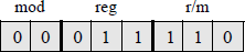
The format for the addressing mode byte is shown below for the target move instruction with a bit configuration of 0001 1110 (1EH). The mod code of 00 indicates that there is no displacement; the reg code of 011 specifies register BL when w = 0; and the r/m field of 110 indicates a direct addressing mode when the mod = 00.
6.1.2 Compare Instruction
The compare (CMP) was introduced in Chapter 5, but more details are presented in this section. The compare instruction compares two integer operands. It subtracts the second source operand from the first source operand and sets the status flags in the EFLAGS register accordingly. Both operands remain unchanged after the subtract operation, whereas a subtract (SUB) operation replaces the destination operand with the difference. The compare instruction is used primarily in conjunction with the jump on condition (Jcc) instruction, which performs a branch operation based on the state of the flags resulting from a compare instruction. The syntax for the compare instruction is shown below.
CMP register/memory, immediate/register/memory
The compare instruction can be used to compare an immediate operand of 8 bits, 16 bits, or 32 bits with the accumulator register. For example,
CMP AL, 4AH
CMP AX, 1B36H
CMP EAX, 45AC7B89H
It can also be used to compare an immediate operand with a memory operand or a register. For example,
CMP [BX], 12ADH
CMP BX, 2244H
It can also be used to compare registers of the same width. For example,
CMP EBX, EDX
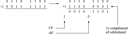
Table 6.5 shows the results of subtracting second source operands from first source operands and the resulting flags, using unsigned operands. The adjust flag, or auxiliary carry, (AF) is set if there is a carry out of or a borrow into the low-order four bits; the carry flag (CF) is set if there is a carry out of or a borrow into the high-order bit position of an arithmetic operation; otherwise it is reset. When subtracting by adding the 2s complement of the subtrahend, the state of the resulting AF and CF flags is inverted.
Compare Operations and the Resulting Flags
First Source Operand |
Second Source Operand |
Resulting Difference |
OF |
SF |
ZF |
AF |
PF |
CF |
|
|---|---|---|---|---|---|---|---|---|---|
7AH |
7AH |
00H |
0 |
0 |
1 |
0 |
1 |
0 |
op1 = op2 |
6CH |
3FH |
2DH |
0 |
0 |
0 |
1 |
1 |
0 |
op1 > op2 |
B5H |
CDH |
E8H |
0 |
1 |
0 |
1 |
1 |
1 |
op1 < op2 |
15H |
32H |
E3H |
0 |
1 |
0 |
0 |
0 |
1 |
op1 < op2 |
63H |
B3H |
B0H |
1 |
1 |
0 |
0 |
0 |
1 |
op1 < op2 |
The overflow flag (OF) is set if the result of an operation is too large or too small to be contained in the destination operand; that is, the number is out of range for the size of the result. The parity flag (PF) is set if the low-order byte of the result has an even number of 1s; otherwise it is reset. The sign flag (SF) is set to the value of the high-order bit position. The zero flag (ZF) is set if the result is zero; otherwise it is reset.
The second example (6CH – 3FH) will be examined in more detail using binary subtraction; that is, the difference will be obtained by adding the 2s complement of the subtrahend to the minuend. The state of the AF flag is reversed from 0 to 1. The state of the carry flag (CF) is reversed from 1 to 0. There is no overflow (OF), because the signs of the operands are different (minuend = 0, 2s complemented subtrahend = 1). The parity flag (PF) is 1, because there are an even number of 1s in the resulting byte (or low-order byte). The sign flag (SF) is 0, because the high-order bit is 0, which is the sign bit for signed operands. The zero flag (ZF) is 0, because the result is nonzero.
The low-order byte of the EFLAGS register is shown below, which will be used in conjunction with the program shown in Figure 6.3 — an assembly language module linked to a C program. Bit positions 1, 3, and 5 are reserved.
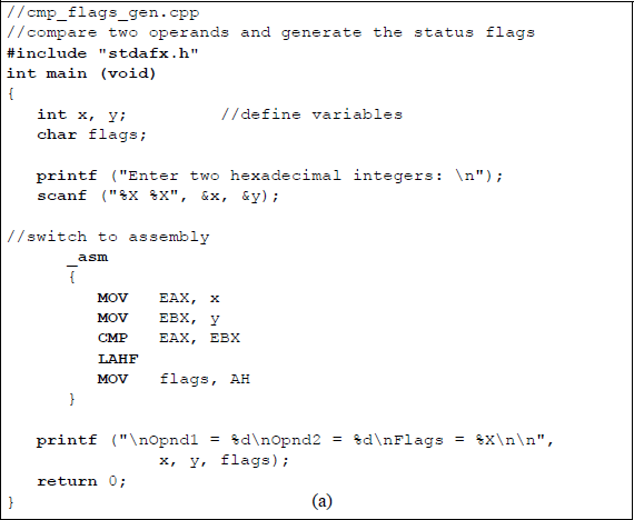
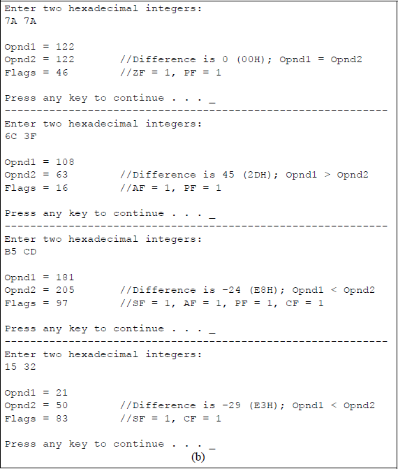
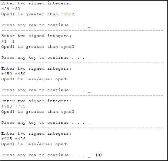
Program to illustrate the CMP instruction and the resulting status flags: (a) the program and (b) the outputs.
7 |
6 |
5 |
4 |
3 |
2 |
1 |
0 |
|---|---|---|---|---|---|---|---|
SF |
ZF |
0 |
AF |
0 |
PF |
1 |
CF |
The flags variable in the program is declared as type char, because only the low-order byte in the EFLAGS register is being used. The user enters two hexadecimal characters, which are stored in int variables x and y. In the assembly language module, x and y are moved to registers EAX and EBX, respectively. The variables are then compared, resulting in the flags being generated.
A new instruction will now be introduced in order to display the flags. This is the load AH from flags (LAHF) instruction, which has a 1-byte operation code. The LAHF instruction copies the low-order byte of the EFLAGS register into the corresponding bit positions of the AH register, but does not alter the flags in the EFLAGS register. The contents of register AH are then moved to the flags variable for display.
In Figure 6.3(b), the first pair of hexadecimal operands are 7A16 (12210) and 7A16 (12210), which results in a difference of zero (0000 0000) after subtracting the second source operand from the first source operand, to yield a flag byte of 0100 0110. Thus, ZF = 1, indicating a result of all zeroes; and PF = 1 in order to maintain odd parity for the byte; that is, there are an even number of 1s in the difference.
The second pair of hexadecimal operands are 6C16 (10810) and 3F16 (6310), which results in a difference of 45 (0010 1101), to yield a flag byte of 0001 0110. Thus, AF = 1, indicating a borrow from bit 4 of the minuend; and PF = 1, because there are an even number of 1s in the difference.
The third pair of operands are B516 (18110) and CD16 (20510), which results in a difference of –24 (1110 1000), to yield a flag byte of 1001 0111. Thus, SF = 1, because bit 7 is a 1; AF = 1, indicating a borrow from bit 4 of the minuend; PF =1, indicating an even number of 1s in the difference; and CF = 1, indicating a borrow into bit 7 of the minuend.
The fourth pair of operands are 1516 (2110) and 3216 (5010), resulting in a difference of –29 (1110 0011), to yield a flag byte of 1000 0011. Thus, SF = 1, because bit 7 is a 1; and CF = 1, indicating a borrow into bit 7 of the minuend.
Another instruction that operates on the EFLAGS register and the AH register is the store AH into flags (SAHF) instruction. The SAHF instruction copies register AH into the low-order byte of the EFLAGS register.
6.1.3 Conditional Jump Instructions
The conditional jump/transfer (Jcc) instructions transfer control to a destination instruction in the same code segment if certain condition codes (cc) are set — the condition is specified in the instruction mnemonic. If the condition is not met, then program execution continues with the next instruction that follows the Jcc instruction. The conditional jump instructions are partitioned into three groups: those that are used with unsigned integers, those that are used with signed integers, and those that are used irrespective of the sign of the operands, as shown in Table 6.6. There are usually two mnemonics associated with each instruction that give alternative names for the instruction; this may facilitate easier understanding of the operation of the instruction.
Conditional Jump Instructions
Mnemonic |
Description |
Flags Examined |
|---|---|---|
Unsigned Conditional Jumps |
||
JA/JNBE |
Jump if above or not below/equal |
(CF or ZF) = 0 |
JAE/JNB |
Jump if above or equal/not below |
CF = 0 |
JB/JNAE |
Jump if below or not above/equal |
CF = 1 |
JBE/JNA |
Jump if below/equal or not above |
(CF or ZF) = 1 |
JE/JZ |
Jump if equal or zero — unsigned/signed |
ZF = 1 |
JNE/JNZ |
Jump if not equal/not zero — unsigned/signed |
ZF = 0 |
Signed Conditional Jumps |
||
JG/JNLE |
Jump if greater or not less/equal |
[(SF xor OF) or ZF] = 0 |
JGE/JNL |
Jump if greater/equal or not less |
(SF xor OF) = 0 |
JL/JNGE |
Jump if less or not greater/equal |
(SF xor OF) = 1 |
JLE/JNG |
Jump if less/equal or not greater |
[(SF xor OF) or ZF] = 1 |
Other Conditional Jumps |
||
JCXZ |
Jump if CX = 0 |
Register CX = 0 |
JECXZ |
Jump if ECX = 0 |
Register ECX = 0 |
JC |
Jump if carry |
CF = 1 |
JNC |
Jump if no carry |
CF = 0 |
JNO |
Jump if no overflow |
OF = 0 |
JO |
Jump if overflow |
OF = 1 |
JNP/JPO |
Jump if parity is odd |
PF = 0 |
JP/JPE |
Jump if parity is even |
PF = 1 |
JNS |
Jump if sign bit = 0 |
SF = 0 |
JS |
Jump if sign bit = 1 |
SF = 1 |
As can be seen from Table 6.6, conditional jump instructions that use the words above or equal in their descriptions refer to unsigned operands; conditional jump instructions that use the words greater or less in their descriptions refer to signed operands. There is no return address for the conditional jump instructions and they do not support far jumps; that is, jumps to other code segments. The destination address is a signed offset that is relative to the contents of the (E)IP register, and thus, resides in the current code segment.
The conditional jump instructions examine the state of one or more flags in the EFLAGS register to determine if a jump should take place. The flags that are inspected are SF, ZF, AF, PF, and CF. Examples will now be presented that illustrate the operation of select conditional jump instructions.
Jump if above (JA) for unsigned numbers The JA instruction will cause a jump to occur if the following equation is true:
(CF or ZF) = 0
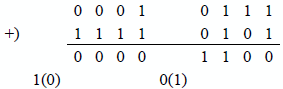
Example 6.1 Let register AL = 1111 1011 (251) and register BL = 0000 0111 (7), then compare the two operands by adding the 2s complement of the subtrahend to the minuend.
Since [(CF = 0) or (ZF = 0)] = 0, therefore, the jump will occur, because the number 251 is above the number 7.
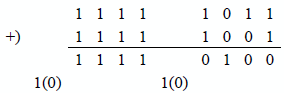
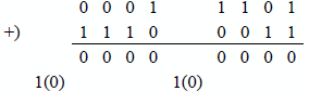
Example 6.2 Let register AL = 1111 1011 (251) and register BL = 1111 1011 (251), then compare the two operands by adding the 2s complement of the subtrahend to the minuend.
Since [(CF = 0) or (ZF = 1)] = 1, therefore, the jump will not occur, because the numbers are equal; that is, the number 251 is not above the number 251.
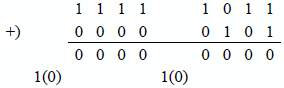
Example 6.3 Let register AL = 0000 1001 (9) and register BL = 0001 1100 (28), then compare the two operands by adding the 2s complement of the subtrahend to the minuend.
Since [(CF = 1) or (ZF = 0)] = 1, therefore, the jump will not occur, because the number 9 is not above the number 28.
Figure 6.4 shows a program to illustrate the jump if above (JA) instruction for unsigned integers. The operands, opnd1 and opnd2, are moved to registers EAX and EBX, respectively, then compared. If opnd1 is above opnd2, then a conditional jump occurs to the label ABOVE, whose address is equal to the contents of register (E)IP plus a signed displacement. A printf () function then displays that operand1 is above operand2. If operand1 is not above operand2, then an unconditional jump occurs to the label BELOW where the printf () function displays that operand1 is not above (below or equal) operand2.
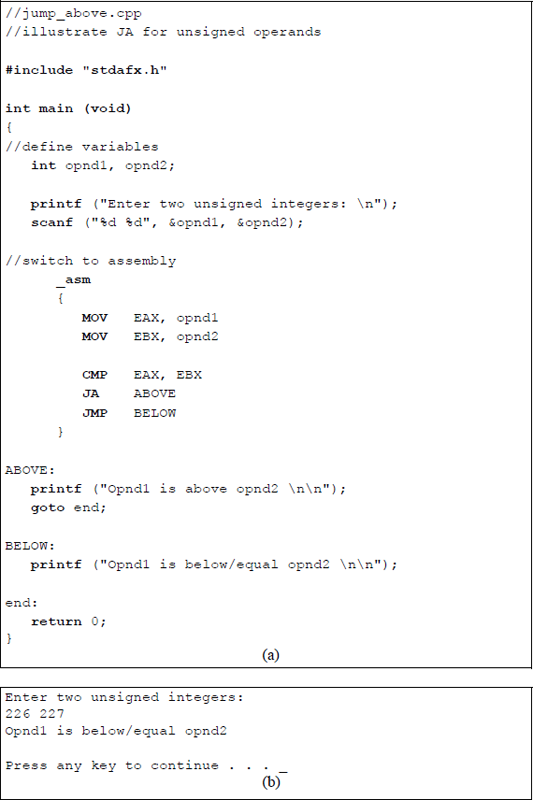
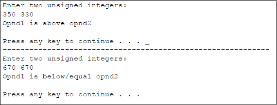
Program to illustrate the use of the JA instruction: (a) the program and (b) the outputs.
The goto instruction simply bypasses the second printf () function if operand1 is above operand2; that is, it is equivalent to an unconditional jump in assembly language. The goto statement is rarely used in C programming, because other forms of control make the program easier to follow, such as the while loop, the if and if ... else constructs, and the for loop. Too many goto statements make the program difficult to follow and to understand, causing the code to become what some programmers refer to as spaghetti code. The goto instruction, therefore, should be used sparingly.
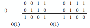
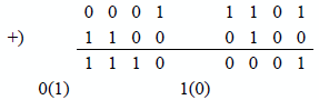
Jump if greater (JG) for signed numbers The JG instruction will cause a jump to occur if the following equation is true:
([SF xor OF) or ZF] = 0
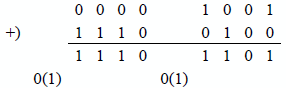
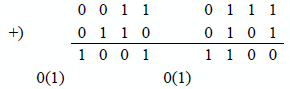
Example 6.4 Let register AL = 0001 0111 (+23) and register BL = 0000 1011 (+11), then compare the two operands by adding the 2s complement of the subtrahend to the minuend.
Since {[(SF = 0) xor (OF = 0)] or ZF = 0} = 0, therefore, the jump will occur, because the number +23 is greater than the number +11.
Example 6.5 Let register AL = 0001 1101 (+29) and register BL = 0001 1101 (+29), then compare the two operands by adding the 2s complement of the subtrahend to the minuend.
Since {[(SF = 0) xor (OF = 0)] or ZF = 1} = 1, therefore, the jump will not occur, because the numbers are equal; that is, the number +29 is not greater than the number +29.
Example 6.6 Let register AL = 0011 0111 (+55) and register BL = 1001 1011, a negative number (–101), then compare the two operands by adding the 2s complement of the subtrahend to the minuend.
Since {[(SF = 1) xor (OF = 1)] or ZF = 0} = 0, therefore, the jump will occur, because +55 is greater than –101.
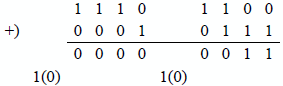
Example 6.7 Let registers AL and BL both contain identical negative operands: 1101 1011 (–37), then compare the two operands by adding the 2s complement of the subtrahend to the minuend.
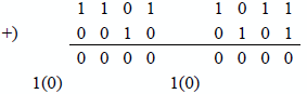
Since {[(SF = 0) xor (OF = 0)] or ZF = 1} = 1, therefore, the jump will not occur, because both operands are equal; that is, the number –37 is not greater than the number –37.
Example 6.8 Let registers AL and BL both contain negative operands: AL = 1110 1100 (–20) and BL = 1110 1001 (–23), then compare the two operands by adding the 2s complement of the subtrahend to the minuend.
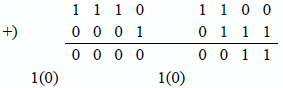
Since {[(SF = 0) xor (OF = 0)] or ZF = 0} = 0, therefore, the jump will occur, because –20 is greater than –23.
Figure 6.5 shows a program to illustrate the jump if greater (JG) instruction for signed integers. The operands, opnd1 and opnd2, are moved to registers EAX and EBX, respectively, then compared. If opnd1 is greater than opnd2, then a conditional jump occurs to the label GREATER, whose address is equal to the contents of register (E)IP plus a signed displacement. A printf () function then displays that operand1 is greater than operand2. If operand1 is not greater than operand2, then an unconditional jump occurs to the label LESS, where the printf () function displays that operand1 is not greater than (less or equal) operand2.
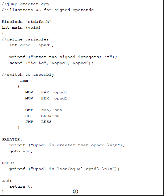
Program to illustrate the use of the JG instruction: (a) the program and (b) the outputs.
Jump if carry (JC) The JC instruction will cause a jump to occur if the following equation is true:
CF = 1
Example 6.9 Let register AL = 0001 1101 (+29) and register BL = 0011 1100 (+60). Then compare the two operands by subtracting the subtrahend from the minuend. This results in a carry out of the high-order bit position and produces a jump.
Example 6.10 Let register AL = 0011 0111 (+55) and register BL = 1001 1011, a negative number (–101), then compare the two operands by subtracting the subtrahend from the minuend. This results in a carry out of the high-order bit position and produces a jump.
Example 6.11 Let registers AL and BL both contain negative operands: AL = 1110 1100 (–20) and BL = 1110 1001 (–23), then compare the two operands by subtracting the subtrahend from the minuend. This results in no carry out of the high-order bit position; therefore, a jump is not executed.
Example 6.12 Let registers AL and BL both contain identical positive operands: 0010 1000 (+40), then compare the two operands by subtracting the subtrahend from the minuend. This results in no carry out of the high-order bit position; therefore, a jump is not executed.
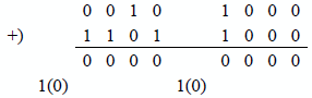
Figure 6.6 shows a program that illustrates the jump if carry (JC) instruction. The operands, opnd1 and opnd2, are moved to registers EAX and EBX, respectively, then compared. A conditional jump will occur if there is a carry out of the high-order bit position, in which case the program jumps to the label CARRY, whose address is equal to the contents of register (E)IP plus a signed displacement. A printf () function then displays that a carry has occurred. If there is no carry, then an unconditional jump occurs to the label NO_CARRY where the printf () function displays that there was no carry.
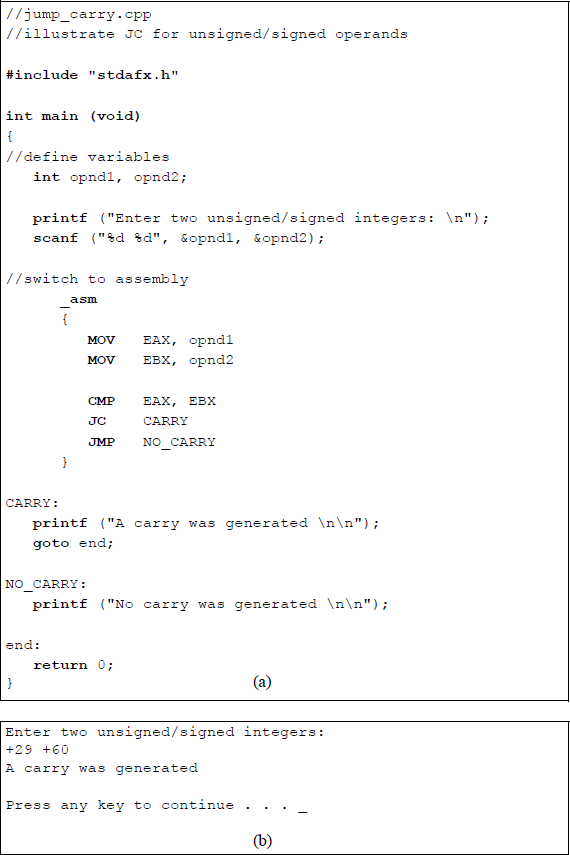
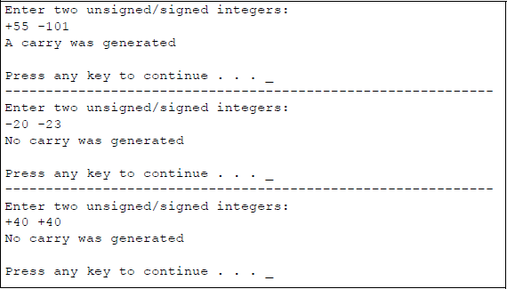
Program to illustrate the use of the JC instruction: (a) the program and (b) the outputs.
6.2 Looping Instructions
There are two categories of software loop instructions: an unconditional loop and conditional loops. Both categories use the (E)CX register as a loop control counter; the counter determines the number of times that the loop will be executed. All loop instructions decrement the count in the (E)CX register by one each time the loop instruction is decoded. If the count is nonzero, then the loop operation is executed; if the count is zero then the loop operation is not executed and program control is transferred to the instruction that immediately follows the loop instruction. The loop instructions do not change the state of the flags in the EFLAGS register.
If the loop instruction is executed, then the destination address is relative to the contents of the (E)IP register and is characterized as a short jump; that is, within –128 bytes to +127 bytes of the current value in the (E)IP register. If the count in the (E)CX register is zero when the loop instruction is initially decoded, then the counter is decremented to a value of 216 = FFFFH if register CX is used or to a value of 232 = FFFFFFFFH if register ECX is used. In order to avoid this situation, the jump if CX register is 0 (JCXZ) or the jump if ECX register is 0 (JECXZ) should be used.
6.2.1 Unconditional Loop
An unconditional loop (LOOP) instruction transfers control to another instruction in the specified range as indicated by a label. The label at the destination address is terminated by a colon, which indicates an instruction within the current code segment. The label name in the LOOP instruction, however, does not have a colon. If the LOOP instruction does not generate a transfer, then the instruction immediately following the LOOP instruction is executed more quickly than if a transfer occurred. This is because fewer clock cycles are required, since there is no address calculation to determine the destination address — the (E)IP register is simply incremented.
The program segment shown below illustrates an unconditional LOOP instruction to transfer control to an instruction with a label specified as NXT_NUM. The program in the loop performs a calculation on numbers in the loop. The body of the loop is executed 20 times.
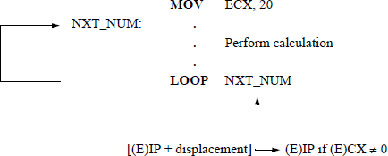
Figure 6.7 shows an assembly language program embedded in a C program to illustrate using the unconditional loop to double the value of a user-entered integer six times. The instruction shown below adds the contents of register EAX to register EAX, effectively doubling the value in EAX.
ADD EAX, EAX
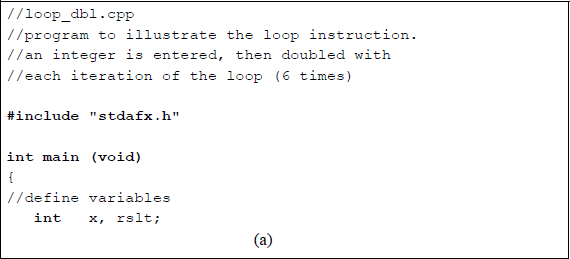
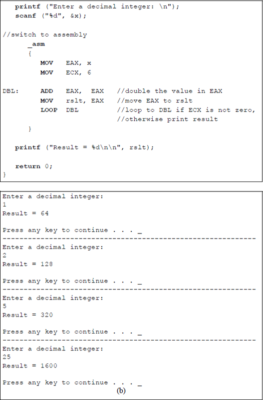
Program to illustrate using the LOOP instruction to double a user-entered integer six times: (a) the program and (b) the outputs.
6.2.2 Conditional Loops
The conditional loop instructions are loop while equal/zero (LOOPE/LOOPZ) and loop while not equal/not zero (LOOPNE/LOOPNZ). The LOOPE and LOOPZ instructions are different mnemonics that refer to the same instruction and they repeat the loop — a short jump — if the (E)CX register is nonzero and the ZF flag is equal to 1. Otherwise, the instruction immediately following the loop instruction is executed. The ZF flag is set by a previous instruction.
The LOOPNE and LOOPNZ are different mnemonics that refer to the same instruction and repeat the loop — a short jump — if (E)CX is nonzero and the ZF flag is equal to 0. Otherwise, the instruction immediately following the loop instruction is executed. The ZF is reset by a previous instruction.
The conditional loop instructions use the count in the (E)CX register to determine the number of times to execute the loop; the count in the (E)CX register is decremented by one for each iteration. None of the flags are affected by these conditional loop instructions.
Figure 6.8 shows an embedded assembly language program illustrating the use of the LOOPNE instruction. Although the program for the loop instruction is relatively simple, it illustrates the principle of how it can be used for certain applications. In the program of Figure 6.8, the count in register ECX is initially set to a value of 20, register EAX is set to a value of 10, and register EBX is set to a value of 1. The conditional loop repeats while register ECX ≠ 0 and the zero flag ZF = 0.
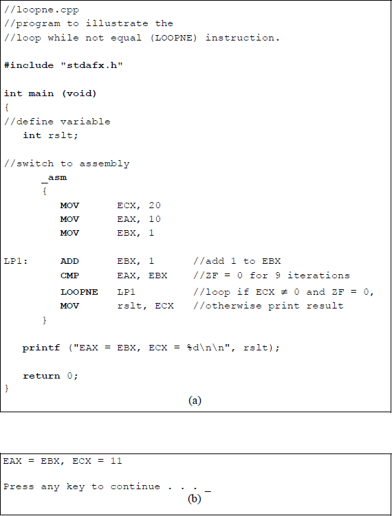
Program to illustrate the function of the LOOPNE instruction: (a) the program and (b) the outputs.
A value of 1 is added to register EBX with each iteration of the loop. After nine iterations, the values in registers EAX and EBX are equal. Therefore, even though the count in register ECX is nonzero (1110), the ZF flag is set to a value of 1, which results in the termination of the loop. The sequence of iterations through the loop is shown below.
Iteration |
EAX |
EBX |
ZF (CMP EAX, EBX) |
ECX |
|---|---|---|---|---|
0 |
10 |
1 |
0 |
20 |
1 |
10 |
2 |
0 |
19 |
2 |
10 |
3 |
0 |
18 |
3 |
10 |
4 |
0 |
17 |
4 |
10 |
5 |
0 |
16 |
5 |
10 |
6 |
0 |
15 |
6 |
10 |
7 |
0 |
14 |
7 |
10 |
8 |
0 |
13 |
8 |
10 |
9 |
0 |
12 |
9 |
10 |
10 |
1 |
11 |
When the program exits the loop, the value in register ECX is moved to the rslt variable. The printf () function then displays the equality of registers EAX and EBX and displays the resulting value (1110) in register ECX. The count in register ECX does not decrement to zero because the ZF flag was set at iteration 9, resulting in the termination of the loop.
6.2.3 Implementing While Loops
The while loop (or while statement) is one of many constructs in the C programming language that operate in a looping manner. The while loop executes a statement or block of statements as long as a test expression is true (nonzero). The statements that are controlled by the while statement loop repeatedly until the expression becomes false (0). Although the while statement is not part of the X86 assembly language instruction set, it can be implemented by using a series of standard assembly language instructions that simulate the structure of a while loop.
Figure 6.9 shows an assembly language program module embedded in a C program. The while structure is contained within the WHILE and END_WHILE labels, which act as delimiters for the assembly language program. The user enters a number in the range of 1 through 9; the number is then moved to register EAX prior to entering the loop, which begins at the WHILE label.
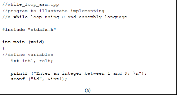
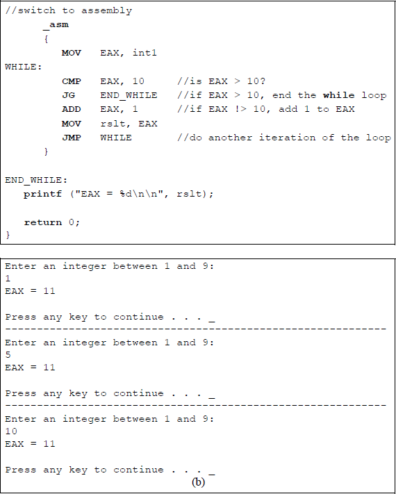
An assembly language module embedded in a C program to simulate a while loop structure: (a) the program and (b) the outputs.
A comparison is made with the contents of register EAX and the number 10 to determine if the value in register EAX is greater than 10. This is done by the following instruction:
CMP EAX, 10
If register EAX is greater than 10, then the loop is exited by the following instruction:
JG END_WHILE
A value of 1 is added to register EAX with each iteration of the loop until the value in EAX is greater than 10. The final contents (1110) of register EAX are then printed.
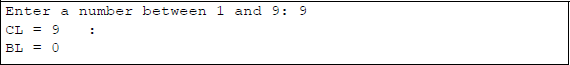
A similar program will now be written entirely in assembly language using the number 9 as an upper limit, as shown in Figure 6.10. This program displays the value of register BL for each iteration of the WHILE loop. The .STACK directive is a simplified way to define the stack segment — the default stack size is 1,024 bytes, but can be changed as required.
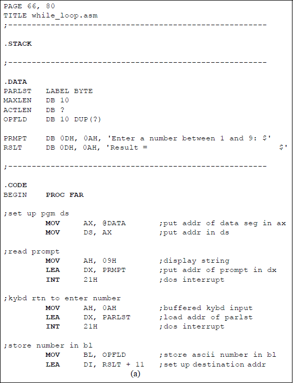
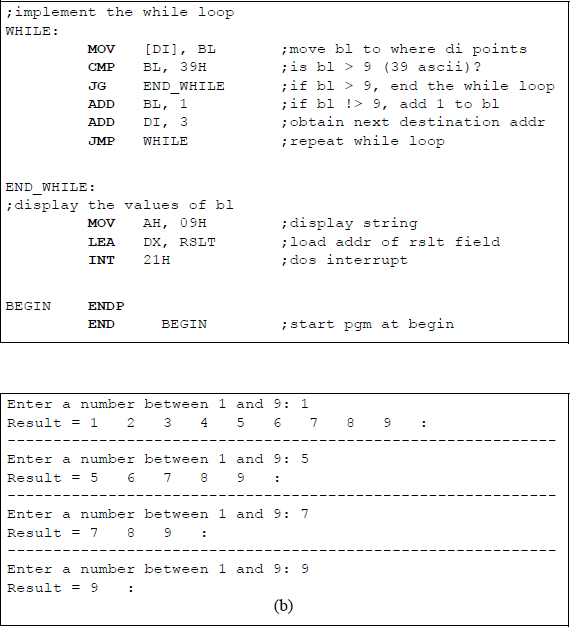
Assembly language program to illustrate the implementation of a while loop: (a) the program and (b) the outputs.
The data segment is defined by the .DATA directive and includes a one-dimensional parameter list array defined as a byte array, labelled PARLST, that is used to store the keyboard input data. The first element of the array, PARLST [0], is called MAXLEN, which defines the maximum number of input character bytes (DB) — in this example, ten is the maximum number of allowable characters, although only one character is needed.
The second array element, PARLST [1], is defined as a byte (DB) called ACTLEN, which stores the actual number of characters entered from the keyboard. The third element of the array, PARLST [2], contains the beginning of the operand field (OPFLD) where the operands from the keyboard are stored — in this example, ten bytes are specified. The last byte in the OPFLD is the Enter character (carriage return ↵).
A prompt field follows the parameter list, labelled PRMPT; this field prompts the user to enter an integer. The final field in the data segment is the result (RSLT) field where the results of the program are stored.
In a similar manner, the code segment is declared by the directive .CODE. A size value can be appended to these simplified segment directives to specify their respective sizes. These directives generate the appropriate segment statements and the corresponding end segment statements.
The address of the data segment (@DATA) is moved into the DS register. Then the prompt is displayed by the following instructions:
MOV AH, 09H
LEA DX, PRMPT
INT 21H
The MOV instruction places 09H, which is the display string function, in the required register AH for the interrupt function call, INT 21H. The LEA instruction places the address of the prompt for the display area in the required register DX. The INT instruction is the function call to execute the function code in register AH.
The next sequence of instructions is similar to those just presented, except that the function (0AH) in register AH is for a buffered keyboard input, which places the keyboard characters in the OPFLD area of the parameter list (PARLST). Data entered from the keyboard is stored in the OPFLD area as American Standard Code for Information Interchange (ASCII) characters. The number that is stored in the OPFLD is then moved to register BL. The address of the display area, RSLT + 11, to store the character from the first iteration of the loop is stored in register DI, which is used as a destination index.
The first instruction of the WHILE loop moves the user-entered number in register BL to the location specified by the contents of register DI ([DI]), where the brackets indicate the contents of. Since ASCII characters are being compared, the contents of register BL are compared to 39H — the upper limit. If the contents of register BL are greater than 9 (39H), then the program jumps to the END_WHILE label and exits the WHILE loop.
If the contents of register BL are not greater than 9, then a value of 1 is added to register BL and the destination address in register DI is incremented by 3, which provides for spacing between successive numbers. Then the next iteration of the loop occurs with an unconditional jump to the label WHILE. The result area (RSLT), containing all of the numbers from the user-entered number to the number 9, is then displayed.
6.2.4 Implementing for Loops
Another common looping technique is the for loop, which is used in the C programming language and in the Verilog Hardware Description Language (HDL). The for loop repeats a statement or block of statements a specific number of times. This is different than the while loop, which repeats the loop as long as a certain condition is met. When the for loop has completed the final loop, the program exits the loop and transfers control to the first statement following the block of statements.
The for loop contains three parts:
An initial condition to assign a value to the counter E(CX) as a control variable to determine the number of iterations for the loop. This is executed once before the beginning of the loop.
A test condition to determine when the loop terminates. This is a jump on condition instruction; for example, a jump if greater than (JG) expression that is executed before the procedural statements of the loop to determine if the loop should execute. The loop is repeated as long as the expression is true. If the expression is false, the loop terminates and the activity flow proceeds to the next statement in the module.
An assignment to modify the control variable, usually an increment or a decrement. This assignment is executed after each execution of the loop and before the next test to terminate the loop. The syntax for a for loop is shown below.
for (initial assignment for the counter; test instruction;
increment/decrement)
Although the for statement is not part of the X86 assembly language instruction set, it can be implemented by using a series of standard assembly language instructions that simulate the structure of a for loop.
Figure 6.11 shows an assembly language module embedded in a C program. The for structure is contained within the FOR and END_FOR labels, which act as delimiters for the assembly language program. The user enters a number in the range of 1 through 9 that is stored in an int variable called count. The number is then moved to register ECX and acts as a loop control variable prior to entering the loop, which begins at the FOR label.
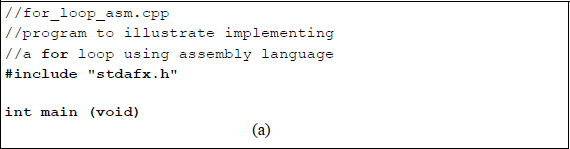
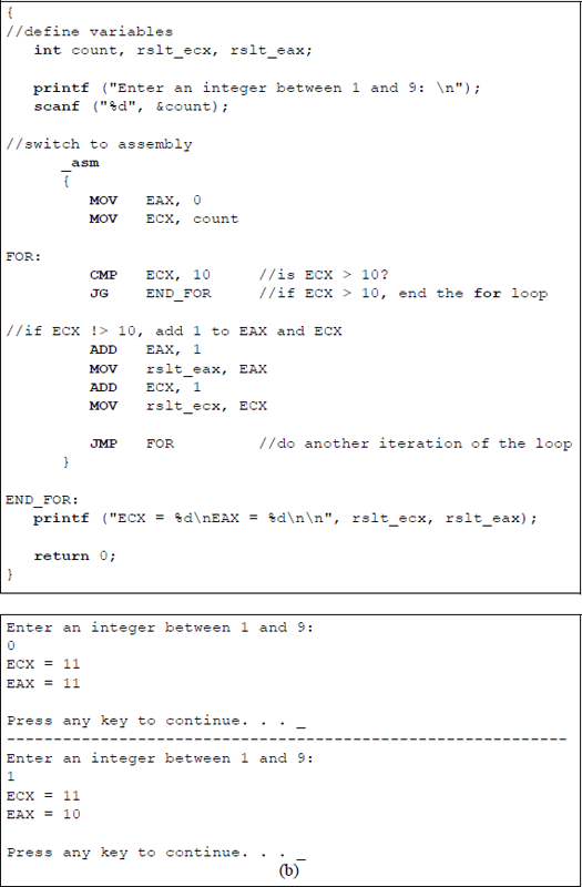
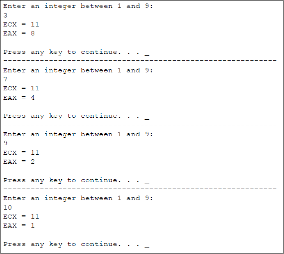
An assembly language module embedded in a C program to simulate a for loop structure: (a) the program and (b) the outputs.
The FOR loop performs an operation on register EAX by incrementing EAX by 1 during each iteration of the loop. The count in register ECX in incremented by 1 near the end of the FOR loop, then checked if it is within range at the beginning of the loop.
The sequence of iterations through the loop is shown below for register ECX and register EAX.
Iteration |
ECX |
EAX |
|---|---|---|
0 |
3 |
0 |
1 |
4 |
1 |
2 |
5 |
2 |
3 |
6 |
3 |
4 |
7 |
4 |
5 |
8 |
5 |
6 |
9 |
6 |
7 |
10 |
7 |
8 |
11 |
8 |
A similar program will now be written entirely in assembly language using the number 9 as an upper limit, as shown in Figure 6.12. This program displays the value of the count in register CL and the value of the data in register BL for each iteration of the FOR loop. The result areas, RSLT1 and RSLT2, contain all of the numbers from the user-entered number to the number 9 in register CL and corresponding data in register BL. The two result areas are displayed using two separate display routines.
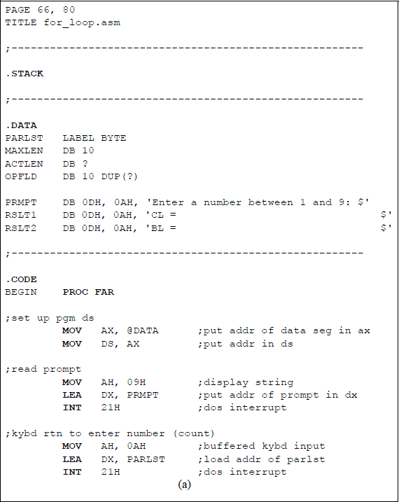
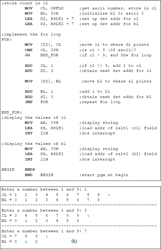
Assembly language program to illustrate the implementation of a for loop: (a) the program and (b) the outputs.
6.3 Problems
6.1 Define a near jump, a short jump, and a far jump. All are unconditional jump instructions.
6.2 Determine if an overflow occurs for the operation shown below. The operands are signed numbers in 2s complement representation.
6.3 Determine if an overflow occurs for the operation shown below. The operands are signed numbers in 2s complement representation.
6.4 Show that no overflow occurs for the operations shown below. The operands are in 2s complement representation.
(a) 1101 0011 + 1100 1110
(b) 0110 1101 − 0110 0011
(c) 1111 1111 − 1111 1111
(d) 1111 1111 + 1111 1111
6.5 Determine the state of the flags for the following operation, where register AX = 73B4H and register BX = 6ACDH:
CMP AX, BX6.6 Determine the state of the flags for the following operation, where register AL = F3H and register BL = 72H:
CMP AL, BL6.7 Determine whether the conditional jump instructions shown below will cause a jump to DEST.
(a) 004FH + 200D JS DEST
(b) FF38H + 200D JZ DEST
6.8 Let AL = 1110 0000B and BL = 1100 0000B. Determine whether the conditional jump instructions shown below will cause a jump to DEST.
(a) CMP AL, BL
JA DEST(b) CMP AL, BL
JG DEST
6.9 Let AL = 1111 1000B and BL = 1111 0000B. Determine whether the conditional jump instruction shown below will cause a jump to LBL1.
CMP AL, BLJG LBL16.10 Let AX = 067CH. Determine whether the conditional jump instruction shown below will cause a jump to BRANCH_ADDR.
CMP AX, 1660DJNE BRANCH_ADDR6.11 Let AX = –405D. Determine whether the conditional jump instruction shown below will cause a jump to BRANCH_ADDR.
CMP AX, FE6CHJGE BRANCH_ADDR6.12 Let AX = 7768H and BX = 9BCAH. Determine if the conditional jump instruction shown below will cause a jump to DEST for the operation AX + BX.
JPO DEST6.13 Determine the number of times that the following program segment executes the body of the loop:
MOV CX, -1LP1: ..LOOP LP16.14 Determine the number of times that the following program segment executes the body of the loop:
MOV CX, 1LP1: ..LOOP LP16.15 Determine the number of times that the following program segment executes the body of the loop:
MOV CX, 10LP1: ..LOOP LP16.16 Determine the number of times that the following program segment executes the body of the loop:
MOV CX, 0LP1: ..LOOP LP16.17 Given the program shown below, determine the contents of register EAX after the program has finished execution.
//loop_add.cpp//determine the contents of register EAX//after execution of the program
#include "stdafx.h"
int main (void)
{//define variableint rslt;//switch to assembly_asm{MOV CX, 4MOV EAX, 2LP1: ADD AX, 3ADD AL, 4LOOP LP1MOV rslt, EAX}
printf ("EAX = %X\n\n", rslt);
return 0;}