Table of Contents for
X86 Assembly Language and C Fundamentals
 X86 Assembly Language and C Fundamentals
Published by
CRC Press, 2015
X86 Assembly Language and C Fundamentals
Published by
CRC Press, 2015
- X86 Assembly Language and C Fundamentals
- Preliminaries
- By the same Author
- X86 Assembly Language and C Fundamentals
- X86 Assembly Language and C Fundamentals
- Preface
- Chapter 1 Number Systems and Number Representations
- Chapter 2 X86 Processor Architecture
- Chapter 3 Addressing Modes
- Chapter 4 C Programming Fundamentals
- Chapter 5 Data Transfer Instructions
- Chapter 6 Branching and Looping Instructions
- Chapter 7 Stack Operations
- Chapter 8 Logical, Bit, Shift, and Rotate Instructions
- Chapter 9 Fixed-Point Arithmetic Instructions
- Chapter 10 Binary-Coded Decimal Arithmetic Instructions
- Chapter 11 Floating-Point Arithmetic Instructions
- Chapter 12 Procedures
- Chapter 13 String Instructions
- Chapter 14 Arrays
- Chapter 15 Macros
- Chapter 16 Interrupts and Input/Output Operations
- Chapter 17 Additional Programming Examples
- Appendix A ASCII Character Codes
- Appendix B Answers to Select Problems
Chapter 1
Number Systems and Number Representations
This chapter discusses positional number systems using various radices (bases), counting in different radices, and conversion from one radix to a different radix. The number systems are presented for both integer and fraction notation. The different number systems covered are binary (radix 2), octal (radix 8), binary-coded octal, decimal (radix 10), binary-coded decimal, hexadecimal (radix 16), and binary-coded hexadecimal. Also, other nontraditional radices are presented to illustrate that the same rules apply to any radix. Various arithmetic operations are provided to demonstrate the four arithmetic operations of addition, subtraction, multiplication, and division.
Number representations are also covered for both positive and negative numbers for the three number representations of sign magnitude, diminished-radix complement, and radix complement. The four arithmetic operations are presented for binary and binary-coded decimal.
1.1 Number Systems
Numerical data are expressed in various positional number systems for each radix, or base. A positional number system encodes a vector of n bits in which each bit is weighted according to its position in the vector. The encoded vector is also associated with a radix r, which is an integer greater than or equal to 2. A number system has exactly r digits in which each bit in the radix has a value in the range of 0 to , thus the highest digit value is one less than the radix. For example, the binary radix has two digits which range from 0 to 1; the octal radix has eight digits which range from 0 to 7. An n-bit integer A is represented in a positional number system as follows:
where . The high-order and low-order digits are and , respectively. The number in Equation 1.1 (also referred to as a vector or operand) can represent positive integer values in the range 0 to . Thus, a positive integer A is written as
The value for A can be represented more compactly as
The expression of Equation 1.2 can be extended to include fractions. For example,
Equation 1.4 can be represented as
Adding 1 to the highest digit in a radix r number system produces a sum of 0 and a carry of 1 to the next higher-order column. Thus, counting in radix r produces the following sequence of numbers:
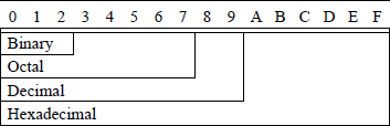
Table 1.1 shows the counting sequence for different radices. The low-order digit will always be 0 in the set of r digits for the given radix. The set of r digits for various radices is given in Table 1.2. In order to maintain one character per digit, the numbers 10, 11, 12, 13, 14, and 15 are represented by the letters A, B, C, D, E, and F, respectively.
Counting Sequence for Different Radices
Decimal |
r = 2 |
r = 4 |
r = 8 |
|---|---|---|---|
0 |
0 |
0 |
0 |
1 |
1 |
1 |
1 |
2 |
10 |
2 |
2 |
3 |
11 |
3 |
3 |
4 |
100 |
10 |
4 |
5 |
101 |
11 |
5 |
6 |
110 |
12 |
6 |
7 |
111 |
13 |
7 |
8 |
1000 |
20 |
10 |
9 |
1001 |
21 |
11 |
10 |
1010 |
22 |
12 |
11 |
1011 |
23 |
13 |
12 |
1100 |
30 |
14 |
13 |
1101 |
31 |
15 |
14 |
1110 |
32 |
16 |
15 |
1111 |
33 |
17 |
16 |
10000 |
100 |
20 |
17 |
10001 |
101 |
21 |
Character Sets for Different Radices
Radix (base) |
Character Sets for Different Radices |
|---|---|
2 |
{0, 1} |
3 |
{0, 1, 2} |
4 |
{0, 1, 2, 3} |
5 |
{0, 1, 2, 3, 4} |
6 |
{0, 1, 2, 3, 4, 5} |
7 |
{0, 1, 2, 3, 4, 5, 6} |
8 |
{0, 1, 2, 3, 4, 5, 6, 7} |
9 |
{0, 1, 2, 3, 4, 5, 6, 7, 8} |
10 |
{0, 1, 2, 3, 4, 5, 6, 7, 8, 9} |
11 |
{0, 1, 2, 3, 4, 5, 6, 7, 8, 9, A} |
12 |
{0, 1, 2, 3, 4, 5, 6, 7, 8, 9, A, B} |
13 |
{0, 1, 2, 3, 4, 5, 6, 7, 8, 9, A, B, C} |
14 |
{0, 1, 2, 3, 4, 5, 6, 7, 8, 9, A, B, C, D} |
15 |
{0, 1, 2, 3, 4, 5, 6, 7, 8, 9, A, B, C, D, E} |
16 |
{0, 1, 2, 3, 4, 5, 6, 7, 8, 9, A, B, C, D, E, F} |
Example 1.1 Count from decimal 0 to 25 in radix 5. Table 1.2 indicates that radix 5 contains the following set of four digits: {0, 1, 2, 3, 4}. The counting sequence in radix 5 is
Example 1.2 Count from decimal 0 to 25 in radix 12. Table 1.2 indicates that radix 12 contains the following set of twelve digits: {0, 1, 2, 3, 4, 5, 6, 7, 8, 9, A, B}. The counting sequence in radix 12 is
1.1.1 Binary Number System
The radix is 2 in the binary number system; therefore, only two digits are used: 0 and 1. The low-value digit is 0 and the high-value digit is . The binary number system is the most conventional and easily implemented system for internal use in a digital computer; therefore, most digital computers use the binary number system. There is a disadvantage when converting to and from the externally used decimal system; however, this is compensated for by the ease of implementation and the speed of execution in binary of the four basic operations: addition, subtraction, multiplication, and division. The radix point is implied within the internal structure of the computer; that is, there is no specific storage element assigned to contain the radix point.
The weight assigned to each position of a binary number is as follows:
where the integer and fraction are separated by the radix point (binary point). The decimal value of the binary number 1011.1012 is obtained by using Equation 1.4, where and for . Therefore,
Digital systems are designed using bistable storage devices that are either reset (logic 0) or set (logic 1). Therefore, the binary number system is ideally suited to represent numbers or states in a digital system, since radix 2 consists of the alphabet 0 and 1. These bistable devices can be concatenated to any length n to store binary data. For example, to store 1 byte (8 bits) of data, eight bistable storage devices are required for the value 0110 1011 (10710). Counting in binary is illustrated in Table 1.3, which shows the weight associated with each of the four binary bit positions. Notice the alternating groups of 1s in Table 1.3 for each of the four columns. A binary number is a group of n bits that can assume 2n different combinations of the n bits. Therefore, the range for n bits is 0 to and the range for four bits is 0 to ; that is 0 to 15, as shown in Table 1.3.
Counting in Binary
Decimal |
Binary |
|||
|---|---|---|---|---|
8 |
4 |
2 |
1 |
|
23 |
22 |
21 |
20 |
|
0 |
0 |
0 |
0 |
0 |
1 |
0 |
0 |
0 |
1 |
2 |
0 |
0 |
1 |
0 |
3 |
0 |
0 |
1 |
1 |
4 |
0 |
1 |
0 |
0 |
5 |
0 |
1 |
0 |
1 |
6 |
0 |
1 |
1 |
0 |
7 |
0 |
1 |
1 |
1 |
8 |
1 |
0 |
0 |
0 |
9 |
1 |
0 |
0 |
1 |
10 |
1 |
0 |
1 |
0 |
11 |
1 |
0 |
1 |
1 |
12 |
1 |
1 |
0 |
0 |
13 |
1 |
1 |
0 |
1 |
14 |
1 |
1 |
1 |
0 |
15 |
1 |
1 |
1 |
1 |
The binary weights for each bit position of an 8-bit integer are shown in Table 1.4 and the binary weights for each bit position of an 8-bit fraction are shown in Table 1.5.
Binary Weights for an 8-Bit Fraction
2‒1 |
2‒2 |
2‒3 |
2‒4 |
2‒5 |
2‒6 |
2‒7 |
2‒8 |
|---|---|---|---|---|---|---|---|
1/2 |
1/4 |
1/8 |
1/16 |
1/32 |
1/64 |
1/128 |
1/256 |
0.5 |
0.25 |
0.125 |
0.0625 |
0.03125 |
0.015625 |
0.0078125 |
0.00390625 |
Each 4-bit binary segment has a weight associated with the segment and is assigned the value represented by the low-order bit of the corresponding segment, as shown in the first row of Table 1.6. The 4-bit binary number in each segment is then multiplied by the value of the segment. Thus, the binary number 0010 1010 0111 1100 0111 is equal to the decimal number 174,02310 as shown below.
Weight Associated with 4-Bit Binary Segments
65536 |
4096 |
256 |
16 |
1 |
|---|---|---|---|---|
0001 |
0001 |
0001 |
0001 |
0001 |
0010 |
1010 |
0111 |
1100 |
0111 |
1.1.2 Octal Number System
The radix is 8 in the octal number system; therefore, eight digits are used, 0 through 7. The low-value digit is 0 and the high-value digit is . The weight assigned to each position of an octal number is as follows:
where the integer and fraction are separated by the radix point (octal point). The decimal value of the octal number 217.68 is obtained by using Equation 1.4, where and for . Therefore,
When a count of 1 is added to 78, the sum is zero and a carry of 1 is added to the next higher-order column on the left. Counting in octal is shown in Table 1.7, which shows the weight associated with each of the three octal positions.
Counting in Octal
Decimal |
Octal |
||
|---|---|---|---|
64 |
8 |
1 |
|
82 |
81 |
80 |
|
0 |
0 |
0 |
0 |
1 |
0 |
0 |
1 |
2 |
0 |
0 |
2 |
3 |
0 |
0 |
3 |
4 |
0 |
0 |
4 |
5 |
0 |
0 |
5 |
6 |
0 |
0 |
6 |
7 |
0 |
0 |
7 |
8 |
0 |
1 |
0 |
9 |
0 |
1 |
1 |
... |
... |
||
14 |
0 |
1 |
6 |
15 |
0 |
1 |
7 |
16 |
0 |
2 |
0 |
17 |
0 |
2 |
1 |
... |
... |
||
22 |
0 |
2 |
6 |
23 |
0 |
2 |
7 |
24 |
0 |
3 |
0 |
25 |
0 |
3 |
1 |
... |
... |
||
30 |
0 |
3 |
6 |
31 |
0 |
3 |
7 |
... |
... |
||
84 |
1 |
2 |
4 |
... |
... |
||
242 |
3 |
6 |
2 |
... |
... |
||
377 |
5 |
7 |
1 |
Binary-coded octal Each octal digit can be encoded into a corresponding binary number. The highest-valued octal digit is 7; therefore, three binary digits are required to represent each octal digit. This is shown in Table 1.5, which lists the decimal digits and indicates the corresponding octal and binary-coded octal (BCO) digits.
Binary-Coded Octal Numbers
Decimal |
Octal |
Binary-Coded Octal |
||
|---|---|---|---|---|
0 |
0 |
000 |
||
1 |
1 |
001 |
||
2 |
2 |
010 |
||
3 |
3 |
011 |
||
4 |
4 |
100 |
||
5 |
5 |
101 |
||
6 |
6 |
110 |
||
7 |
7 |
111 |
||
8 |
10 |
001 |
000 |
|
9 |
11 |
001 |
001 |
|
10 |
12 |
001 |
010 |
|
11 |
13 |
001 |
011 |
|
... |
... |
... |
||
20 |
24 |
010 |
100 |
|
21 |
25 |
010 |
101 |
|
... |
... |
... |
||
100 |
144 |
001 |
100 |
100 |
101 |
145 |
001 |
100 |
101 |
... |
... |
... |
||
267 |
413 |
100 |
001 |
011 |
... |
... |
... |
||
385 |
601 |
110 |
000 |
001 |
1.1.3 Decimal Number System
The radix is 10 in the decimal number system; therefore, ten digits are used, 0 through 9. The low-value digit is 0 and the high-value digit is . The weight assigned to each position of a decimal number is as follows:
where the integer and fraction are separated by the radix point (decimal point). The value of 635710 is immediately apparent; however, the value is also obtained by using Equation 1.4, where and for . That is,
When a count of 1 is added to decimal 9, the sum is zero and a carry of 1 is added to the next higher-order column on the left. The following example contains both an integer and a fraction:
Binary-coded decimal Each decimal digit can be encoded into a corresponding binary number; however, only ten decimal digits are valid. The highest-valued decimal digit is 9, which requires four bits in the binary representation. Therefore, four binary digits are required to represent each decimal digit. This is shown in Table 1.9, which lists the ten decimal digits (0 through 9) and indicates the corresponding binary-coded decimal (BCD) digits. Table 1.9 also shows BCD numbers of more than one decimal digit.
Binary-Coded Decimal Numbers
Decimal |
Binary-Coded Decimal |
||
|---|---|---|---|
0 |
0000 |
||
1 |
0001 |
||
2 |
0010 |
||
3 |
0011 |
||
4 |
0100 |
||
5 |
0101 |
||
6 |
0110 |
||
7 |
0111 |
||
8 |
1000 |
||
9 |
1001 |
||
10 |
0001 |
0000 |
|
11 |
0001 |
0001 |
|
12 |
0001 |
0010 |
|
... |
... |
||
124 |
0001 |
0010 |
0100 |
... |
... |
||
365 |
0011 |
0110 |
0101 |
1.1.4 Hexadecimal Number System
The radix is 16 in the hexadecimal number system; therefore, 16 digits are used, 0 through 9 and A through F, where by convention A, B, C, D, E, and F correspond to decimal 10, 11, 12, 13, 14, and 15, respectively. The low-value digit is 0 and the high-value digit is (F). The weight assigned to each position of a hexadecimal number is as follows:
where the integer and fraction are separated by the radix point (hexadecimal point). The decimal value of the hexadecimal number 6A8C.D41616 is obtained by using Equation 1.4, where and for . Therefore,
When a count of 1 is added to hexadecimal F, the sum is zero and a carry of 1 is added to the next higher-order column on the left. Note that when inserting hexadecimal numbers in an assembly language program manually, the first digit must be a number 0 through 9, then the digits A through F, if required, followed by the hexadecimal radix specifier H.
Binary-coded hexadecimal Each hexadecimal digit corresponds to a 4-bit binary number as shown in Table 1.10. All 24 values of the four binary bits are used to represent the 16 hexadecimal digits. Table 1.10 also indicates hexadecimal numbers of more than one digit. Counting in hexadecimal is shown in Table 1.11. Table 1.12 summarizes the characters used in the four number systems: binary, octal, decimal, and hexadecimal.
Binary-Coded Hexadecimal Numbers
Decimal |
Hexadecimal |
Binary-Coded Hexadecimal |
||
|---|---|---|---|---|
0 |
0 |
0000 |
||
1 |
1 |
0001 |
||
2 |
2 |
0010 |
||
3 |
3 |
0011 |
||
4 |
4 |
0100 |
||
5 |
5 |
0101 |
||
6 |
6 |
0110 |
||
7 |
7 |
0111 |
||
8 |
8 |
1000 |
||
9 |
9 |
1001 |
||
10 |
A |
1010 |
||
11 |
B |
1011 |
||
12 |
C |
1100 |
||
13 |
D |
1101 |
||
14 |
E |
1110 |
||
15 |
F |
1111 |
||
... |
... |
... |
||
124 |
7C |
0111 |
1100 |
|
... |
... |
... |
||
365 |
16D |
0001 |
0110 |
1101 |
Counting in Hexadecimal
Decimal |
Hexadecimal |
||
|---|---|---|---|
256 |
16 |
1 |
|
162 |
161 |
160 |
|
0 |
0 |
0 |
0 |
1 |
0 |
0 |
1 |
2 |
0 |
0 |
2 |
3 |
0 |
0 |
3 |
4 |
0 |
0 |
4 |
5 |
0 |
0 |
5 |
6 |
0 |
0 |
6 |
7 |
0 |
0 |
7 |
8 |
0 |
0 |
8 |
9 |
0 |
0 |
9 |
10 |
0 |
0 |
A |
11 |
0 |
0 |
B |
12 |
0 |
0 |
C |
13 |
0 |
0 |
D |
14 |
0 |
0 |
E |
15 |
0 |
0 |
F |
16 |
0 |
1 |
0 |
17 |
0 |
1 |
1 |
... |
... |
||
26 |
0 |
1 |
A |
27 |
0 |
1 |
B |
... |
... |
||
30 |
0 |
1 |
E |
31 |
0 |
1 |
F |
... |
... |
||
256 |
1 |
0 |
0 |
... |
... |
||
285 |
1 |
1 |
D |
... |
... |
||
1214 |
4 |
B |
E |
1.1.5 Arithmetic Operations
The arithmetic operations of addition, subtraction, multiplication, and division in any radix can be performed using identical procedures to those used for decimal arithmetic. The operands for the four operations are shown in Table 1.13.
Operands Used for Arithmetic Operations
Addition |
Subtraction |
Multiplication |
Division |
|---|---|---|---|
Augend |
Minuend |
Multiplicand |
Dividend |
+) Addend |
‒) Subtrahend |
×) Multiplier |
÷) Divisor |
Sum |
Difference |
Product |
Quotient, Remainder |
Radix 2 addition Figure 1.1 illustrates binary addition of unsigned operands. The sum of column 1 is 210 (102); therefore, the sum is 0 with a carry of 1 to column 2. The sum of column 2 is 410 (1002); therefore, the sum is 0 with a carry of 0 to column 3 and a carry of 1 to column 4. The sum of column 3 is 310 (112); therefore, the sum is 1 with a carry of 1 to column 4. The sum of column 4 is 410 (1002); therefore, the sum is 0 with a carry of 0 to column 5 and a carry of 1 to column 6. The unsigned values of the binary operands are shown in the rightmost column together with the resulting sum.
Radix 2 subtraction The rules for subtraction in radix 2 are as follows:
Figure 1.2 provides an example of binary subtraction using the above rules for unsigned operands. An alternative method for subtraction — used in computers — will be given in Section 1.2 when number representations are presented. In Figure 1.2 column 3, the difference is 1 with a borrow from the minuend in column 4, which changes the minuend in column 4 to 0.

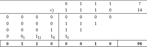
Radix 2 multiplication Multiplying in binary is similar to multiplying in decimal. Two n-bit operands produce a 2n-bit product. Figure 1.3 shows an example of binary multiplication using unsigned operands, where the multiplicand is 710 and the multiplier is 1410. The multiplicand is multiplied by the low-order multiplier bit (0), producing a partial product of all zeroes. Then the multiplicand is multiplied by the next higher-order multiplier bit (1), producing a left-shifted partial product of 0000 111. The process repeats until all bits of the multiplier have been used.
Radix 2 division The division process is shown in Figure 1.4, where the divisor is n bits and the dividend is 2n bits. This division procedure uses a sequential shift-sub-tract-restore technique. Figure 1.4 shows a divisor of 510 (01012) and a dividend of 1310 (0000 11012), resulting in a quotient of 210 (00102) and a remainder of 310 (00112).
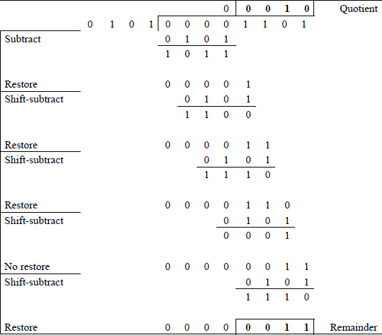
The divisor is subtracted from the high-order four bits of the dividend. The result is a partial remainder that is negative — the leftmost bit is 1 — indicating that the divisor is greater than the four high-order bits of the dividend. Therefore, a 0 is placed in the high-order bit position of the quotient. The dividend bits are then restored to their previous values with the next lower-order bit (1) of the dividend being appended to the right of the partial product. The divisor is shifted right one bit position and again subtracted from the dividend bits.
This restore-shift-subtract cycle repeats for a total of three cycles until the partial remainder is positive — the leftmost bit is 0, indicating that the divisor is less than the corresponding dividend bits. This results in a no-restore cycle in which the previous partial remainder (0001) is not restored. A 1 bit is placed in the next lower-order quotient bit and the next lower-order dividend bit is appended to the right of the partial remainder. The divisor is again subtracted, resulting in a negative partial remainder, which is again restored by adding the divisor. The 4-bit quotient is 0010 and the 4-bit remainder is 0011.
The results can be verified by multiplying the quotient (0010) by the divisor (0101) and adding the remainder (0011) to obtain the dividend. Thus, .
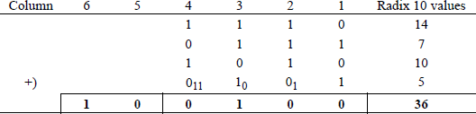
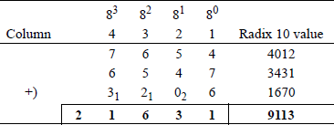
Radix 8 addition Figure 1.5 illustrates octal addition. The result of adding column 1 is 178, which is a sum of 1 with a carry of 2. The result of adding column 2 is 118, which is a sum of 3 with a carry of 1. The remaining columns are added in a similar manner, yielding a result of 216318 or 911310.
Radix 8 subtraction Octal subtraction is slightly more complex than octal addition. Figure 1.6 provides an example of octal subtraction. In column 2 (81), a 1 is subtracted from minuend 58 leaving a value of 48; the 1 is then added to the minuend in column 1 (28). This results in a difference of 68 in column 1, as shown below.
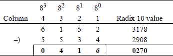
In a similar manner, in column 4 (83), a 1 is subtracted from minuend 68 leaving a value of 58; the 1 is then added to the minuend in column 3 (18), leaving a difference of , as shown below.
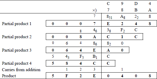
Radix 8 multiplication An example of octal multiplication is shown in Figure 1.7, where the multiplicand = 74638 and the multiplier = 52108. The multiplicand is multiplied by each multiplier digit in turn to obtain a partial product. Except for the first partial product, each successive partial product is shifted left one digit. The subscripts in partial products 3 and 4 represent carries obtained from multiplying the multiplicand by the multiplier digits. When all of the partial products are obtained, the partial products are added following the rules for octal addition.
Radix 8 division An example of octal division is shown in Figure 1.8. The first quotient digit is 38 which, when multiplied by the divisor 178, yields a result of 558. Subtraction of the partial remainder and multiplication of the quotient digit times the divisor are accomplished using the rules stated above for octal arithmetic.
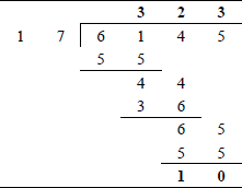
The results of Figure 1.8 can be verified as follows:
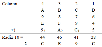
Radix 16 addition An example of hexadecimal addition is shown in Figure 1.9. The subscripted numbers indicate carries from the previous column. The decimal value of the hexadecimal addition of each column is also shown. To obtain the hexadecimal value of the column, a multiple of 1610 is subtracted from decimal value and the difference is the hexadecimal value and the multiple of 1610 is the carry. For example, the decimal sum of column 1 is 28. Therefore, (C16) with a carry of 1 to column 2. In a similar manner, the decimal sum of column 2 is 40 + 1 (carry) = 41. Therefore, (916) with a carry of 2 to column 3.
Radix 16 subtraction Hexadecimal subtraction is similar to subtraction in any other radix. An example of hexadecimal subtraction is shown in Figure 1.10.
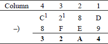
The superscripted numbers indicate borrows from the minuends. For example, the minuend in column 2 borrows a 1 from the minuend in column 3; therefore, column 2 becomes . This is more readily apparent if the hexadecimal numbers are represented as binary numbers, as shown below.
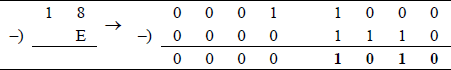
In a similar manner, column 3 becomes with a borrow from column 4. Column 4 becomes .
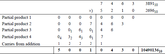
Radix 16 multiplication Figure 1.11 shows an example of hexadecimal multiplication. Multiplication in radix 16 is slightly more complex than multiplication in other radices. Each multiplicand is multiplied by each multiplier digit in turn to form a partial product. Except for the first partial product, each partial product is shifted left one digit position. The subscripted digits in Figure 1.11 indicate the carries formed when multiplying the multiplicand by the multiplier digits.
Consider the first row of Figure 1.11 — the row above partial product 1.
In a similar manner, the remaining partial products are obtained. Each column of partial products is then added to obtain the product.
Radix 16 division Figure 1.12 (a) and Figure 1.12 (b) show two examples of hexadecimal division. The results of Figure 1.12 can be verified as follows:
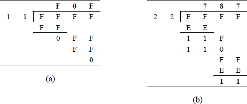
For Figure 1.12 (a):
For Figure 1.12 (b):
1.1.6 Conversion between Radices
Methods to convert a number in radix ri to radix rj will be illustrated in this section. The following conversion methods will be presented:
Binary |
→ |
Decimal |
Octal |
→ |
Decimal |
Hexadecimal |
→ |
Decimal |
Decimal |
→ |
Binary |
Decimal |
→ |
Octal |
Decimal |
→ |
Hexadecimal |
Binary |
→ |
Octal |
Binary |
→ |
Hexadecimal |
Octal |
→ |
Binary |
Octal |
→ |
Hexadecimal |
Hexadecimal |
→ |
Binary |
Hexadecimal |
→ |
Octal |
Octal |
→ |
Binary-coded octal |
Hexadecimal |
→ |
Binary-coded hexadecimal |
Decimal |
→ |
Binary-coded decimal |
Comparison between the following formats will also be examined:
There will also be examples to illustrate converting between two nonstandard radices and an example to determine the value of an unknown radix for a given radix 10 number.
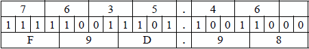
Binary to decimal Conversion from any radix r to radix 10 is easily accomplished by using Equation 1.2 for integers, and Equation 1.4 for numbers consisting of integers and fractions. Equation 1.2 and Equation 1.4 are reproduced below as Equation 1.6 and Equation 1.7 for convenience.
The binary number 1111000.1012 will be converted to an equivalent decimal number. The weight by position is as follows:
Octal to decimal The octal number 217. 658 will be converted to an equivalent decimal number. The weight by position is as follows:
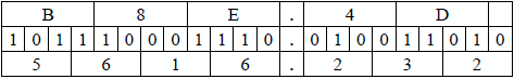
Hexadecimal to decimal The hexadecimal number 5C2.4D16 will be converted to an equivalent decimal number. The weight by position is as follows:
Decimal to binary To convert a number in radix 10 to any other radix r, repeatedly divide the integer by radix r, then repeatedly multiply the fraction by radix r. The first remainder obtained when dividing the integer is the low-order digit. The first integer obtained when multiplying the fraction is the high-order digit.
The decimal number 186.62510 will be converted to an equivalent binary number. The process is partitioned into two parts: divide the integer 18610 repeatedly by 2 until the quotient equals zero; multiply the fraction 0.625 repeatedly by 2 until a zero result is obtained or until a certain precision is reached.
Therefore, . Converting from decimal to BCD does not yield the same results as converting from decimal to binary, because BCD does not use all 16 combinations of four bits — only ten combinations are used.
Decimal to octal The decimal number 219.6210 will be converted to an equivalent octal number. The integer 21910 is divided by 8 repeatedly and the fraction 0.6210 is multiplied by 8 repeatedly to a precision of three digits.
Therefore, .
Decimal to hexadecimal The decimal number 195.82812510 will be converted to an equivalent hexadecimal number. The integer is divided by 16 repeatedly and the fraction is multiplied by 16 repeatedly.
Therefore, .
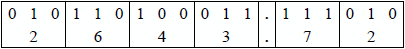
Binary to octal When converting a binary number to octal, the binary number is partitioned into groups of three bits as the number is scanned from right to left for integers and scanned left to right for fractions. If the leftmost group of the integer does not contain three bits, then leading zeroes are added to produce a 3-bit octal digit; if the rightmost group of the fraction does not contain three bits, then trailing zeroes are added to produce a 3-bit octal digit. The binary number 10110100011.111012 will be converted to an octal number as shown below.
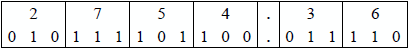
Binary to hexadecimal When converting a binary number to hexadecimal, the binary number is partitioned into groups of four bits as the number is scanned from right to left for integers and scanned left to right for fractions. If the leftmost group of the integer does not contain four bits, then leading zeroes are added to produce a 4-bit hexadecimal digit; if the rightmost group of the fraction does not contain four bits, then trailing zeroes are added to produce a 4-bit hexadecimal digit. The binary number 11010101000.11110101112 will be converted to a hexadecimal number as shown below.

Octal to binary When converting an octal number to binary, three binary digits are entered that correspond to each octal digit, as shown below.
When converting from octal to binary-coded octal (BCO) and from octal to binary, the binary bit configurations are identical. This is because the octal number system uses all eight combinations of three bits.
Octal to hexadecimal To convert from octal to hexadecimal, the octal number is first converted to BCO then partitioned into 4-bit segments to form binary-coded hexadecimal (BCH). The BCH notation is then easily changed to hexadecimal, as shown below.
Hexadecimal to binary To convert from hexadecimal to binary, substitute the four binary bits for the hexadecimal digits according to Table 1.10 as shown below.

When converting from hexadecimal to BCH and from hexadecimal to binary, the binary bit configurations are identical. This is because the hexadecimal number system uses all sixteen combinations of four bits.
Hexadecimal to octal When converting from hexadecimal to octal, the hexadecimal digits are first converted to binary. Then the binary bits are partitioned into 3-bit segments to obtain the octal digits, as shown below.
Conversion from radix 5 to radix 10 Equation 1.4 is reproduced below as Equation 1.8 for convenience and will be used to convert the following radix 5 number to an equivalent radix 10 number: 2134.435.
Convert from radix ri to any other radix rj To convert any nondecimal number Ari in radix ri to another nondecimal number Arj in radix rj, first convert the number Ari to decimal using Equation 1.4, then convert the decimal number to radix rj by using repeated division and/or repeated multiplication. The radix 9 number 1259 will be converted to an equivalent radix 7 number. First 1259 is converted to radix 10.
Then, convert 10410 to radix 7.
Verify the answer.
Determine the value of an unknown radix The equation shown below has an unknown radix a. This example will determine the value of radix a.
Verify the answer.
1.2 Number Representations
Computers use both positive and negative numbers, and since a computer cannot recognize a plus (+) or a minus (–) sign, an encoding method must be established to represent the sign of a number in which both positive and negative numbers are distributed as evenly as possible.
There must also be a method to differentiate between positive and negative numbers; that is, there must be an easy way to test the sign of a number. Detection of a number with a zero value must be straightforward. The leftmost (high-order) digit is usually reserved for the sign of the number. Consider the following number A with radix r :
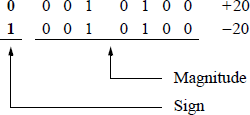
where digit an – 1 has the value shown in Equation 1.9.
The remaining digits of A indicate either the true magnitude or the magnitude in a complemented form. There are three conventional ways to represent positive and negative numbers in a positional number system: sign magnitude, diminished-radix complement, and radix complement. In all three number representations, the high-order digit is the sign of the number, such that: 0 = positive and = negative, as shown in Equation 1.9.
1.2.1 Sign Magnitude
In this representation, an integer has the decimal range shown in Equation 1.10.
where the number zero is considered to be positive. Thus, a positive number A is represented as shown in Equation 1.11.
A negative number with the same absolute value as shown in Equation 1.12.
In sign-magnitude notation, the positive version, +A, differs from the negative version, –A, only in the sign digit position. The magnitude portion is identical for both positive and negative numbers of the same absolute value.
There are two problems with sign-magnitude representation. First, there are two representations for the number 0; specifically, + 0 and – 0. Ideally there should be a unique representation for the number 0. Second, when adding two numbers of opposite signs, the magnitudes of the numbers must be compared to determine the sign of the result. This is not necessary in the other two methods that are presented in subsequent sections. Sign-magnitude notation is used primarily for representing fractions in floating-point notation.
Examples of sign-magnitude notation are shown below using 8-bit binary numbers and decimal numbers that represent both positive and negative values. Notice that the magnitude parts are identical for both positive and negative numbers for the same radix.
Radix 2
Radix 10
where 0 represents a positive number in radix 10, and 9 () represents a negative number in radix 10. Again, the magnitudes of both numbers are identical.
1.2.2 Diminished-Radix Complement
This is the (r – 1) complement in which the radix is diminished by 1 and an integer has the decimal range shown in Equation 1.13, which is the same as the range for sign-magnitude integers, although the numbers are represented differently. The number zero is again considered to be positive. Thus, a positive number A is represented as shown in Equation 1.14. A negative number is represented as shown in Equation 1.15, in which all the digits are inverted.
For the complement, individual digits can be determined as shown in Equation 1.16. For example, if ai = 1 in radix 2, then the diminished-radix complement of ai is . In a similar manner, if ai = 0 in radix 2, then the diminished-radix complement of ai is . In binary notation (), the diminished-radix complement is the 1s complement.
Positive and negative integers have the ranges shown below and are represented as shown in Equation 1.14 and Equation 1.15, respectively.
To obtain the 1s complement of a binary number, simply complement (invert) all the bits. Thus, 0011 11002 (+ 6010) becomes 1100 00112 (− 6010). To obtain the value of a positive binary number, the 1s are evaluated according to their weights in the positional number system, as shown below.
To obtain the value of a negative binary number, the 0s are evaluated according to their weights in the positional number system, as shown below.
When performing arithmetic operations on two operands, comparing the signs is straightforward, because the leftmost bit is a 0 for positive numbers and a 1 for negative numbers. There is, however, a problem when using the diminished-radix complement. There is a dual representation of the number zero, because a word of all 0s (+ 0) becomes a word of all 1s (– 0) when complemented. This does not allow the requirement of having a unique representation for the number zero to be attained. The examples shown below represent the diminished-radix complement for different radices.
Example 1.3 The binary number 1001 11012 will be 1s complemented. The number has a decimal value of – 98. To obtain the 1s complement, subtract each digit in turn from 1, the highest number in the radix. Or in the case of binary, simply invert each bit. Therefore, the 1s complement of 1001 11012 is 0110 00102, which has a decimal value of + 98.

To verify the operation, add the negative and positive numbers to obtain 1111 11112, which is zero in 1s complement notation.
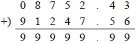
Example 1.4 The diminished-radix complement (9s complement) of 08752.4310, will be obtained, where 0 is the sign digit indicating a positive number. The 9s complement is obtained by using Equation 1.15 and Equation 1.16. When a number is complemented in any form, the number is negated. Therefore, the sign of the complemented radix 10 number is . The remaining digits of the number are obtained by using Equation 1.16, such that each digit in the complemented number is obtained by subtracting the given digit from 9. Therefore, the 9s complement of 08752.4310 is
The sign digit is . If the above answer is negated, then the original number will be obtained. Thus, the 9s complement of 91247.5610 = 08752.4310; that is, the 9s complement of –1247.5610 is +8752.4310, as written in conventional sign magnitude notation for radix 10.
To verify the operation, add the negative and positive numbers to obtain 9999910, which is zero in 9s complement notation.
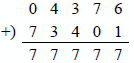
Example 1.5 The diminished-radix complement of the positive radix 8 number 043768 will be 7s complemented. To obtain the 7s complement, subtract each digit in turn from 7 (the highest number in the radix), as shown below to obtain the negative number with the same absolute value. The sign of the positive number is 0 and the sign of the negative number is 7.
To verify the operation, add the negative and positive numbers to obtain 777778, which is zero in 7s complement notation.
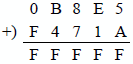
Example 1.6 The diminished-radix complement of the positive radix 16 number 0B8E516 will be 15s complemented. To obtain the 15s complement, subtract each digit in turn from 15 (the highest number in the radix), as shown below to obtain the negative number with the same absolute value. The sign of the positive number is 0 and the sign of the negative number is F.
To verify the operation, add the negative and positive numbers to obtain FFFFF16, which is zero in 15s complement notation.
1.2.3 Radix Complement
This is the r complement, where an integer has the following decimal range:
where the number zero is positive. A positive number A is represented as
and a negative number as
where A′ is the diminished-radix complement. Thus, the radix complement is obtained by adding 1 to the diminished-radix complement; that is, . Note that all three number representations have the same format for positive numbers and differ only in the way that negative numbers are represented, as shown in Table 1.14 for n-bit numbers.
Number Representations for Positive and Negative Integers of the Same Absolute Value for Radix r
Number Representation |
Positive Numbers |
Negative Numbers |
|---|---|---|
Sign magnitude |
||
Diminished-radix complement |
||
Radix complement |
Another way to obtain the radix complement of a number is to keep the low-order 0s and the first 1 unchanged and to complement (invert) the remaining high-order bits. Thus, the radix complement (2s complement) of the binary number 0101 1100 (+92) is 1010 0100 (–92). To obtain the value of a negative number in radix 2, the 0s are evaluated according to their weights in the positional number system, then 1 is added to the value obtained. There is a unique zero for binary numbers in radix complement — when the number zero is 2s complemented, the bit configuration does not change; that is, the 2s complement of 0000 0000 is .
1.2.4 Arithmetic Operations
This section will concentrate on fixed-point binary, binary-coded decimal (BCD), and floating point operations, since these are the dominant number representations in computers. Examples of addition, subtraction, multiplication, and division will be presented for these three number representations.
Binary addition Numbers in radix complement representation are designated as signed numbers, specifically as 2s complement numbers in binary. The sign of a binary number can be extended to the left indefinitely without changing the value of the number. For example, the numbers 000010102 and 00000000010102 both represent a value of + 1010; the numbers 111101102 and 11111111101102 both represent a value of – 1010.
Thus, when an operand has its sign extended to the left, the expansion is achieved by setting the extended bits equal to the leftmost (sign) bit. This is equivalent to the X86 instructions CBW (convert byte to word), CWDE (convert word to doubleword), and CDQE (convert doubleword to quadword). The maximum positive number consists of a 0 followed by a field of all 1s, depending on the word size of the operand. Similarly, the maximum negative number consists of a 1 followed by a field of all 0s, depending on the word size of the operand.
The radix (or binary) point can be in any fixed position in the number — thus the radix point is referred to as a fixed-point radix. For integers, however, the radix point is positioned to the immediate right of the low-order bit position.
Overflow occurs when the result of an arithmetic operation (usually addition) exceeds the word size of the machine; that is, the sum is not within the representable range of numbers provided by the number representation. For numbers in 2s complement representation, the range is from to . For two n-bit numbers
and are the sign bits of operands A and B, respectively. Overflow can be detected by either of the following two equations:
where the symbol “•” is the logical AND operator, the symbol “+” is the logical OR operator, the symbol “⊕” is the exclusive-OR operator as defined below, and cn–1 and cn–2 are the carry bits out of positions n – 1 and n – 2, respectively.
Thus, overflow produces an erroneous sign reversal and is possible only when both operands have the same sign. An overflow cannot occur when adding two operands of different signs, since adding a positive number to a negative number produces a result that falls within the limit specified by the two numbers.
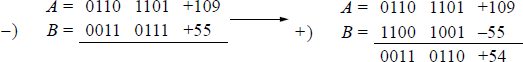
Binary subtraction The operands used for subtraction are the minuend and subtrahend. The rules for binary subtraction are not easily applicable to computer subtraction. The method used by most processors is to add the radix complement (2s complement) of the subtrahend to the minuend; that is, change the sign of the minuend then add the two operands, as shown below.
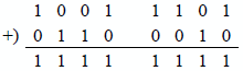
The diminished-radix complement is rarely used in arithmetic applications because of the dual interpretation of the number zero (0000 ... 0000 and 1111 ... 1111). The example shown below illustrates another disadvantage of the diminished-radix complement. Given the two radix 2 numbers shown below, in 1s complement representation, the difference will be obtained.
A ‒ B = A + B′ (1s complement of B)
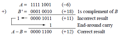
When performing a subtract operation using 1s complement operands, an end-around carry will result if at least one operand is negative. As can be seen above, the result will be incorrect (+ 11) if the carry is not added to the intermediate result. Although 1s complementation may seem easier than 2s complementation, the result that is obtained after an add operation is not always correct. In 1s complement notation, the final carry-out cn−1 cannot be ignored. If the carry-out is zero, then the result is correct. Thus, 1s complement subtraction may result in an extra add cycle to obtain the correct result.
Binary multiplication The multiplication of two n-bit operands results in a 2n-bit product, where and to yield . Multiplication of two binary numbers can be accomplished by a variety of methods. These methods include the sequential add-shift technique, the Booth algorithm, bit-pair recoding, a 2-dimension planar array, a table lookup technique, and a method using memory.
The different methods for multiplying two binary numbers are beyond the scope of this book; however, the sequential add-shift technique will be presented in this section as a representative method. Multiplication of two fixed-point binary numbers in 2s complement representation using the add-shift method is done by a process of successive add and shift operations. The process consists of multiplying the multiplicand by each multiplier bit as the multiplier is scanned right to left. If the multiplier bit is a 1, then the multiplicand is copied as a partial product; otherwise, 0s are inserted as a partial product. The partial products inserted into successive lines are shifted left one bit position from the previous partial product. The partial products are then added to form the product.
The sign of the product is determined by the signs of the operands. If the signs are the same, then the sign of the product is plus; if the signs are different, then the sign of the product is minus. In this sequential add-shift technique, however, the multiplier must be positive. When the multiplier is positive, the bits are treated the same as in the sign-magnitude representation. When the multiplier is negative, the low-order 0s and the first 1 are treated the same as a positive multiplier, but the remaining high-order 1s of a negative multiplier are treated as 1s corresponding to their bit position and not as sign bits. Therefore, the algorithm treats the multiplier as unsigned, or positive.
The problem is easily solved by forming the 2s complement of both the multiplier and the multiplicand. An alternative approach is to 2s complement the negative multiplier, leaving the multiplicand unchanged. Depending on the signs of the initial operands, it may be necessary to complement the product.
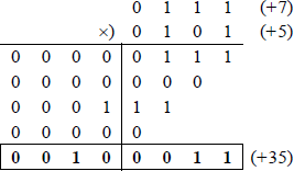
The example shown below in Figure 1.13 uses the add-shift method to multiply the positive operands of 01112 (+ 710) and 01012 (+ 510). Since both operands are positive, the product will be positive (+ 3510).
Binary division Division has two operands that produce two results, as shown below. Unlike multiplication, division is not commutative; that is, , except when .
Like multiplication, there are many ways to perform division on two fixed-point binary operands, all of which are also beyond the scope of this book. These methods include the sequential shift add/subtract technique for restoring and nonrestoring division, SRT division, multiplicative division, and division using a 2-dimension planar array. All operands for a division operation comply with the following equation:
The remainder has a smaller value than the divisor and has the same sign as the dividend. If the divisor B has n bits, then the dividend A has 2n bits and the quotient Q and remainder R both have n bits, as shown below.
The sign of the quotient is and is determined by the rules of algebra; that is,
Multiplication is a sequential add-shift operation, whereas division is a shift add/ subtract operation. The result of a shift add/subtract operation determines the next operation in the division sequence. If the partial remainder is negative, then the carry-out is 0 and becomes the low-order quotient bit q0. The partial remainder thus obtained is restored to the value of the previous partial remainder. This technique is referred to as restoring division. If the partial remainder is positive, then the carry-out is 1 and becomes the low-order quotient bit q0. In this case, the partial remainder is not restored.
An example of restoring division using a hardware algorithm is shown in Figure 1.14, where the dividend in register-pair A Q is 0000 01112 (+710) and the divisor in register B is 00112 (+310). The algorithm is implemented with a subtractor and a 2n-bit shift register.
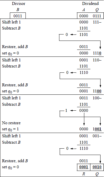
The first operation in Figure 1.14 is to shift the dividend left 1 bit position, then subtract the divisor, which is accomplished by adding the 2s complement of the divisor. Since the result of the subtraction is negative, the dividend is restored by adding back the divisor, and the low-order quotient bit q0 is set to 0. This sequence repeats for a total of four cycles — the number of bits in the divisor. If the result of the subtraction was positive, then the partial remainder is placed in register A, the high-order half of the dividend, and q0 is set to 1.
The division algorithm is slightly more complicated when one or both of the operands are negative. The operands can be preprocessed and/or the results can be postprocessed to achieve the desired results. The negative operands are converted to positive numbers by 2s complementation before the division process begins. The resulting quotient is then 2s complemented, if necessary.
Unlike multiplication, overflow can occur in division. This happens when the high-order half of the dividend is greater than or equal to the divisor. Also, division by zero must be avoided. Both of these problems can be detected before the division process begins by subtracting the divisor from the high-order half of the dividend. If the difference is positive, then an overflow or a divide by zero has been detected.
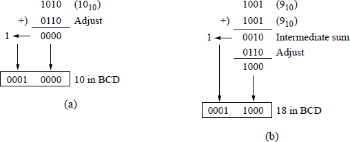
Binary-coded decimal addition When two binary-coded decimal (BCD) digits are added, the range is 0 to 18. If the carry-in cin = 1, then the range is 0 to 19. If the sum digit is ≥ 10 (10102), then it must be adjusted by adding 6 (01102). This excess-6 technique generates the correct BCD sum and a carry to the next higher-order digit, as shown below in Figure 1.15 (a). A carry-out of a BCD sum will also cause an adjustment to be made to the sum — called the intermediate sum — even though the intermediate sum is a valid BCD digit, as shown in Figure 1.15 (b).
There are three conditions that indicate when the intermediate sum of a BCD addition should be adjusted by adding six, as shown in Equation 1.22, where c8 is the carry-out of the high-order bit, b8 b4 = 11 or b8 b2 = 11.
The algorithms used for BCD arithmetic are basically the same as those used for fixed-point arithmetic for radix 2. The main difference is that BCD arithmetic treats each digit as four bits, whereas fixed-point arithmetic treats each digit as a bit. Shifting operations are also different — decimal shifting is performed on 4-bit increments.
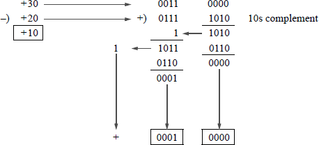
Binary-coded decimal subtraction Subtraction in BCD is essentially the same as in fixed-point binary: add the rs complement of the subtrahend to the minuend, which for BCD is the 10s complement. Example 1.7 shows a subtract operation using BCD numbers. Negative results can remain in 10s complement notation or be recom-plemented to sign-magnitude notation with a negative sign.
Example 1.7 The following decimal numbers will be subtracted using BCD arithmetic: minuend = + 30 and subtrahend = + 20 to yield a difference of +10, as shown in Figure 1.16. This can be considered as true subtraction, because the result is the difference of the two numbers, ignoring the signs. A carry-out of 1 from the high-order decade indicates a positive number. A carry-out of 0 from the high-order decade indicates a negative number in 10s complement notation. The number can be changed to an absolute value by recomplementing the number and changing the sign to indicate a negative value.
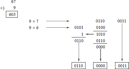
Binary-coded decimal multiplication The multiplication algorithms for decimal multiplication are similar to those for fixed-point binary multiplication except in the way that the partial products are formed. In binary multiplication, the multiplicand is added to the previous partial product if the multiplier bit is a 1. In BCD multiplication, the multiplicand is multiplied by each digit of the multiplier and these subpartial products are aligned and added to form a partial product. When adding digits to obtain a partial product, adjustment may be required to form a valid BCD digit. Example 1.8 illustrates BCD multiplication.
Multiplication of two BCD operands can also be accomplished by using highspeed read-only memory (ROM). The concatenated four bits of the multiplicand and the four bits of the multiplier constitute the memory address. The outputs from the memory are valid BCD digits — no correction is required. All corrections (or adjustments) are accomplished by the memory programming.
Decimal multiplication can also be facilitated by using a table lookup method. This is similar to the table lookup method for fixed-point multiplication. The multiplicand table resides in memory.
Example 1.8 The following decimal numbers will be multiplied using BCD arithmetic: multiplicand = + 67 and multiplier = + 9, resulting in a product of + 603, as shown in Figure 1.17.
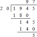
Binary-coded decimal division The method of decimal division presented here is analogous to the binary search method used in programming, which is a systematic way of searching an ordered database. The method begins by examining the middle of the database. For division, the method adds or subtracts multiples of the divisor or partial remainder. The arithmetic operation is always in the following order:
This method requires four cycles for each quotient digit. The first operation is – 8 × the divisor. If the result is less than zero, then 4 × the divisor is added to the partial remainder; if the result is greater than or equal to zero, then 8 is added to a quotient counter and 4 × the divisor is subtracted from the partial remainder. The process repeats for ± 4 × the divisor, ± 2 × the divisor, and ± 1 × the divisor. Whenever +8, +4, +2, or +1 is added to the quotient counter, the sum of the corresponding additions is the quotient digit. Whenever a partial remainder is negative, the next version of the divisor is added to the partial remainder; whenever a partial remainder is positive, the next version of the divisor is subtracted from the partial remainder. Example 1.9 illustrates this technique.
Example 1.9 Let the dividend = 1945 and the divisor = 20 to yield a quotient of 97 and a remainder of 5. Figure 1.18 shows the decimal version and Figure 1.19 shows the application of the BCD algorithm for the same decimal operands.
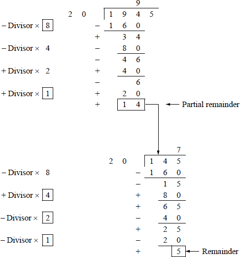
Example of BCD division using the BCD algorithm for the decimal operands shown in Figure 1.18.
Floating-point addition Floating-point numbers consist of the following three fields: a sign bit, s; an exponent, e; and a fraction, f. These parts represent a number that is obtained by multiplying the fraction, f , by a radix, r, raised to the power of the exponent, e, as shown in Equation 1.23 for the number A, where f and e are signed fixed-point numbers, and r is the radix (or base).
The exponent is also referred to as the characteristic; the fraction is also referred to as the significand or mantissa. Figure 1.20 shows the format for 32-bit single-precision and 64-bit double-precision floating-point numbers. The single-precision format consists of a sign bit that indicates the sign of the number, an 8-bit signed exponent, and a 24-bit fraction. The double-precision format consists of a sign bit, an 11-bit signed exponent, and a 52-bit fraction.
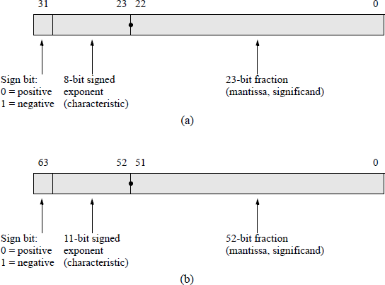
Floating-point formats for the IEEE Std 754-1985 (reaffirmed 1990): (a) 32-bit single precision and (b) 64-bit double precision.
Although the fraction can be represented in sign-magnitude, diminished-radix complement, or radix complement, the fraction is predominantly expressed in sign-magnitude representation, where the sign bit is bit 31 and the magnitude is bits 22 through 0 for the single-precision format.
When adding or subtracting floating-point numbers, the exponents are compared and made equal. This comparison results in a right shift of the fraction with the smaller exponent. If the exponents are eA and eB, then the shift amount is equal to the absolute value of ; that is, . The comparison is easier if the exponents are unsigned — a simple comparator can be used for the comparison. Therefore, as the exponents are being formed, a bias constant is added to the exponents such that all exponents are positive internally.
Fractions in the IEEE format are normalized; that is, the leftmost significant bit is a 1. Since there will always be a 1 to the immediate right of the radix point, the 1 bit is not explicitly shown — it is an implied 1.
Floating-point addition is defined as shown in Equation 1.24 for two numbers A and B, where and . The terms shown below are shifting factors to shift the fraction with the smaller exponent.
This is analogous to a divide operation, since is equivalent to the term , which is a right shift.
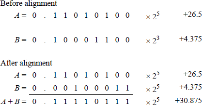
Figure 1.21 illustrates an example of floating-point addition. The fractions must be properly aligned before addition can take place; therefore, the fraction with the smaller exponent is shifted right and the exponent is adjusted by increasing the exponent by one for each bit position shifted.
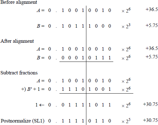
Floating-point subtraction The subtraction of two fractions is identical to the subtraction algorithm presented in fixed-point subtraction. If the signs of the operands are the same and the operation is subtraction, then this is referred to as true subtraction and the fractions are subtracted. If the signs of the operands are different and the operation is addition, then this is also specified as true subtraction.
All operands will consist of normalized fractions properly aligned with biased exponents. Floating-point subtraction is defined as shown in Equation 1.25 for two numbers A and B, where and . An example of floating-point subtraction is shown in Figure 1.22 for two operands, A = +36.5 and B = +5.75.
Floating-point multiplication Floating-point multiplication is slightly easier than addition or subtraction, because the exponents do not have to be compared and the fractions do not have to be aligned. For floating-point multiplication, the exponents are added and the fractions are multiplied. Both operations can be done in parallel. Any of the algorithms presented in binary fixed-point multiplication can be used to multiply the floating-point fractions.
Floating-point multiplication is defined as shown in Equation 1.26, which shows fraction multiplication and exponent addition performed simultaneously.
Multiplication using the single-precision format generates a double-precision 2n-bit product; therefore, the resulting fraction is 46 bits. However, the range of a single-precision fraction in conjunction with the exponent is sufficiently accurate so that a single-precision result is usually adequate. Therefore, the low-order half of the fraction can be truncated, which may require a rounding procedure to be performed. The rounding techniques of truncation rounding, adder-based rounding, and von Neumann rounding are covered in Chapter 2.
The sign of the product is determined by the signs of the floating-point numbers. If the signs are the same, then the sign of the product is positive; if the signs are different, then the sign of the product is negative. This can be determined by the exclusive-OR of the two signs, as shown in Equation 1.27.
The example shown in Figure 1.23 uses the sequential add-shift method with 8-bit operands. A multiplicand fraction is multiplied by a multiplier with partial product D = 0000 0000 to produce a product of . Register A contains the normalized multiplicand fraction, fract_a; register prod contains the high-order n bits of the partial product (initially set to all zeroes); and register B contains the normalized multiplier fraction, fract_b.
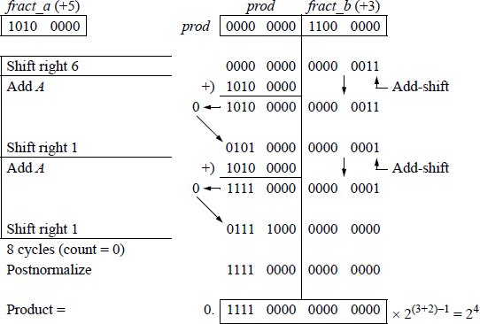
Example of floating-point multiplication using the sequential add-shift method for two 8-bit operands.
Since the multiplication involves two n-bit operands, a count-down sequence counter, count, is set to a value that represents the number of bits in one of the operands. The counter is decremented by one for each step of the add-shift sequence. When the counter reaches a value of zero, the operation is finished and the product is normalized, if necessary.
If the low-order bit of register fract_b is equal to zero, then zeroes are added to the partial product and the sum is loaded into register prod. In this case, it is not necessary to perform an add operation — a right shift can accomplish the same result. However, it may require less logic if the same add-shift sequence occurs for each cycle. The sequence counter is then decremented by one. If the low-order bit of register fract_b is equal to one, then the multiplicand is added to the partial product. The sum is loaded into register prod and the sequence counter is decremented.
Floating-point division Floating-point division performs two operations in parallel: fraction division and exponent subtraction. Fraction division can be accomplished using any of the methods for fixed-point division. The dividend is usually 2n bits and the divisor is n bits; that is, the dividend conforms to the double-precision format and the divisor conforms to the single-precision format.
Floating-point division is defined as shown in Equation 1.28, which shows fraction division and exponent subtraction performed simultaneously.
Figure 1.24 shows floating-point division using the sequential shift-subtract/add restoring division method for a dividend fraction and a divisor fraction to yield a quotient of and a remainder of .
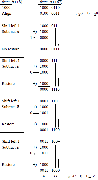
Example of floating-point division using the sequential shift-subtract/add restoring division method.
Since the high-order half of the dividend is greater than or equal to the divisor, the dividend is shifted right one bit position to prevent overflow. In the first cycle of this 4-cycle example, the dividend is shifted left one bit position and the divisor is subtracted from the high-order four bits of the dividend by adding the 2s complement of the divisor. The difference produces a 0 in the leftmost bit of the partial remainder, indicating that the divisor is less than the corresponding dividend bits. This results in a no-restore cycle in which the partial remainder (0000) is not restored. A 1 bit is placed in the next lower-order quotient bit and appended to the right of the low-order dividend bits.
Then the resulting dividend is shifted left one bit position and the divisor is subtracted from the high-order four bits of the dividend. The result is a partial remainder that is negative — the leftmost bit is 1. Therefore, the high-order four bits of the partial remainder are restored to their previous values by adding the divisor. Then a 0 is placed in the next lower-order bit position of the quotient and appended to the right of the low-order dividend bits.
This restore-shift-subtract cycle repeats for a total of four cycles, resulting in a 4bit quotient of 1000 and a 4-bit remainder of 0011.
1.3 Problems
1.1 Convert the following unsigned binary numbers to decimal:
(a) 1111 00002
(b) 1000 0001.1112
1.2 Convert the following unsigned binary numbers to decimal and hexadecimal:
(a) 0100 1101.10112
(b) 0100 1101.10112
1.3 Convert the unsigned binary number 0111 11012 to decimal.
1.4 Convert the signed binary number 1100 11002 to decimal.
1.5 Convert the octal number 173.258 to decimal.
1.6 Convert the binary-coded octal number 110 010 101BCO to decimal.
1.7 Convert the decimal number 487510 to hexadecimal.
1.8 Convert the hexadecimal number AF6C.B5616 to decimal.
1.9 Add the following binary numbers to yield a 12-bit sum:
1.10 Obtain the difference of the following binary numbers:
1.11 Convert the hexadecimal number 4A3CB16 to binary and octal.
1.12 Convert the following octal numbers to hexadecimal: 65368 and 634578.
1.13 Convert the binary number 0100 1101.10112 to decimal and hexadecimal notation.
1.14 Convert 76548 to radix 3.
1.15 Represent the decimal numbers +54, −28, +127, and −13 in sign magnitude, diminished-radix complement, and radix complement for radix 2 using eight bits.
1.16 Multiply the unsigned binary numbers 11112 and 00112.
1.17 Obtain the radix complement of F8B616.
1.18 Obtain the radix complement of 543206.
- 1.19 The numbers shown below are in sign-magnitude representation. Convert the numbers to 2s complement representation for radix 2 with the same numerical value using eight bits.
Sign magnitude |
2s complement |
|---|---|
1001 1001 |
|
0001 0000 |
|
1011 1111 |
1.20 Perform the following binary subtraction using the diminished-radix complement method:
1.21 Add the following BCD numbers:
1.22 Obtain the sum of the following radix 3 numbers:
1.23 Multiply the two binary numbers shown below, which are in radix complementation.
1.24 Let A and B be two binary numbers in 2s complement representation as shown below, where A′ and B′ are the 1s complement of A and B, respectively. Perform the operation listed below. The answer is to be an 8-bit number in 2s complement representation.
1.25 The operands shown below are to be added using decimal (BCD) addition.