Table of Contents for
Cryptography and Network Security
 Cryptography and Network Security
Published by
Pearson Education India, 2016
Cryptography and Network Security
Published by
Pearson Education India, 2016
- Cover
- Title Page
- Engineering Chemistry
- Contents
- Foreword - 1
- Foreword - 2
- Preface
- Acknowledgements
- CHAPTER 1 Cryptography
- CHAPTER 2 Mathematics of Modern Cryptography
- CHAPTER 3 Classical Encryption Techniques
- CHAPTER 4 Data Encryption Standard
- Chapter 5 Secure Block Cipher and Stream Cipher Technique
- Chapter 6 Advanced Encryption Standard (AES)187
- Chapter 7 Public Key Cryptosystem
- Chapter 8 Key Management and Key Distribution
- Chapter 9 Elliptic Curve Cryptography
- Chapter 10 Authentication Techniques
- Chapter 11 Digital Signature
- Chapter 12 Authentication Applications
- Chapter 13 Application Layer Security
- Chapter 14 Transport Layer Security
- Chapter 15 IP Security
- Chapter 16 System Security
- Appendix: Frequently Asked University Questions with Solutions
- Basic Mechanical Engineering
Chapter 8
Key Management and Key Distribution
8.1 Introduction to Key Management
Key management is the process of generating, distributing and maintaining the keys that are necessary for making a secure communication. There are many key management schemes that are available in the literature that are used for supporting multicast communication [4–5]. Since multicasting is an efficient and necessary communication mechanism for group-oriented applications such as interactive group games, video on demand, TV over Internet and e-learning, provision of security to such systems is an important and challenging issue. In order to provide secure multicasting, there are many multicast routing algorithms. Even though, the existing multicast routing algorithms provide effective means for communicating data, these algorithms are targeted by malicious users who modify them in such a way that the packets are multiplied and routed. This leads to congestion in the network and the confidential messages are easily accessed by illegitimate users. Moreover, the existing internet protocol (IP) multicast [7] saves the network bandwidth by sending the source data only to the members by routing them using a multicast tree that spans only the members of the group and covers all the members of the group. Multicast delivery over the Internet can be performed when all the devices that participate in the multicast communication have been enabled for multicast communication. In such a scenario, the multicast groups are identified by group addresses and hence any node of the network can freely join or leave a group at any time using the internet group management protocol (IGMP). Moreover, IP multicasting uses the datagram’s destination address to specify multicast delivery. IP multicasting uses class D addresses with the format shown in Figure 8.1.
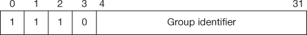
Figure 8.1 IP multicast address format
The first four digits contain 1110, which is used for the identification of multicast address. Bits 4 through 31 identify a particular multicast group. The group field does not contain a network address since there is no single network to which all the hosts belong like class A, B and C type of IP addresses. When expressed in dotted decimal notation, multicast addresses range from 224.0.0.0 to 239.255.255.255.
In a multicast communication, the multicast source sends the multicast data only to a specific multicast address. Since IGMP is running between both the subnet-routers and the attached hosts, each subnet-router periodically sends an IGMP-based query to the hosts on its subnet whether they are interested in the multicast communication. If any host is interested in the current contents of the multicast communication, such host sends an IGMP-Report to the subnet multicast router in order to indicate the willingness and also the address of the session. Upon receiving this join request, the subnet-router runs a multicast routing protocol that allows the new member to join the multicast group. Whenever a host wants to leave from the current multicast communication session, the corresponding multicast subnet-router deletes it from the multicast group directory. Therefore, information about the hosts in a multicast communication must be stored and maintained using a membership directory. Moreover, a member can join or leave a group at any time. In addition, a user can become a member of more than one multicast group. Hence, it is necessary to classify the nature of the groups based on the duration of the members of a multicast communication group.
Groups in multicast communication can be classified into static and dynamic groups. In static groups, membership of the group is predetermined and does not change during the communication. Therefore, the static approach distributes an unchanged group key (GK) to the members of the group when they join or leave from the multicast group. Moreover, they do not provide necessary solutions for changing the GK when the group membership changes which is not providing forward/backward secrecy. In dynamic groups, membership can change after participating in a few multicast communications. Therefore, in a dynamic group communication, members can either join or leave from the service at any time. Dynamic groups are merely appropriate for many multicast applications. Moreover, in this book, all explanations related to group communications focus only on dynamic groups. When a new member joins into the service, it is the responsibility of the group centre (GC) to prevent new members from having access to previous data. This provides backward secrecy in a secure multimedia communication. Similarly, when an existing group member leaves from any group, he/she should not have further access to the multicast communication which provides forward secrecy. The backward and forward secrecy can be achieved only through the use of effective key management schemes.
Generally, the key management schemes are divided into two types, namely centralized and distributed key management schemes. In both the schemes, the sender computes a common GK based on the users share that can be used for encrypting and decrypting the data. Hence, each key management scheme makes use of the combinations of two types of encryption method. First level is public key encryption in which users will be generating private and public key values. The second level is a secret key (SK)/symmetric encryption method in which a common GK is computed based on the each users private and public values. Using this GK, the multicast data can be encrypted and decrypted in the group. In the distributed key management scheme, members they themselves compute the GK. In contrast to this, the GK is computed by the GC and it is sent as a multicast message to the group users in a secure way in centralized key management scheme. This section discusses about centralized key management scheme.
Figure 8.2 illustrates the functional description of the centralized key management scheme. This model has a GC that handles three types of keys used in a centralized key management approach. In this scheme, when a new user sends a join request to the GC, it assigns a private key (PK) initially to each user in a secure way which is sent as a unicast message. The GC utilizes this public key to encrypt subgroup key (SGK), which is a public key for a set of users in the key updating/rekeying process. The key updating is the process of changing the key when the group membership changes in the multicast group. This encrypted SGK is sent as a multicast message to the users. Now, the users whose public keys are used in the key updating process can decrypt this message by using their own secret key or public key. The key updating is the process of changing the keys whenever group membership changes.
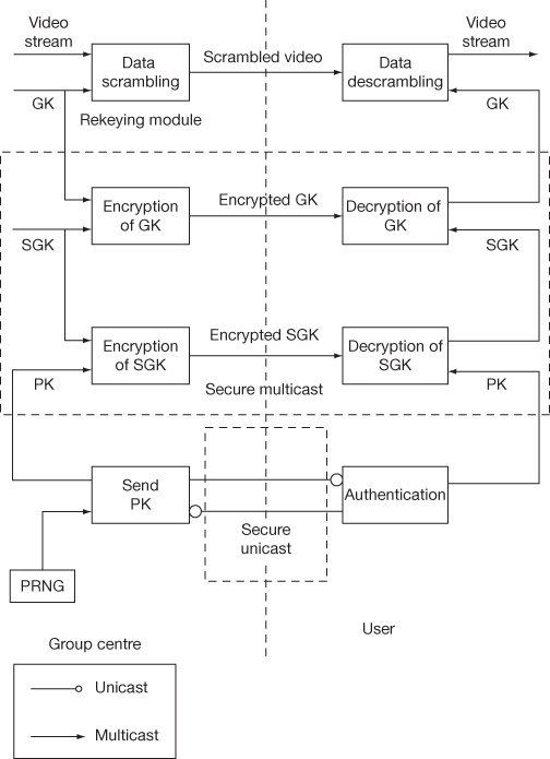
Figure 8.2 Functional description of centralized key management and distribution
In order to efficiently distribute the GK which is common to all the users of the group, SGK acts as a key to encrypt GK. The encrypted GK by using SGK forms another key updating or rekeying message. In the receiving end, the users can obtain GK by using their common SGK while receiving the rekeying message from the GC side. After that, as shown in Figure 8.2, the video data is scrambled by using a GK which is generated in a random manner. The receivers can use GK to descramble the video stream which is sent as a multicast communication from GC in a secure way. Usually, the GC updates SGK and GK in centralized key management scheme whenever the group membership changes in a group communication.
8.2 Centralized vs Distributed Key Management
As stated before, the key management schemes are divided into two types, namely, centralized and distributed key management schemes. In the centralized key management scheme, a trusted third party is used to control the activities of the members. These activities include member registration, key generation, key distribution and key updating in the case of group communication. Moreover, the trusted third party called GC/trusted authority is responsible interacting and controlling the group members in the centralized key management scheme. In contrast, the keys in a distributed key management scheme are computed and maintained with the coordination of the members. Distributed key management schemes are divided into two types, namely, fully contributed key management and partially contributed key management schemes. In a fully contributed distributed key management scheme, the users themselves contribute to form and distribute the key which helps to maintain the secrecy and group membership that provides security to the group communication. In a partial contributed key management scheme, both the users and the GC are responsible for generating and maintaining the keys and group membership. In such a scenario, the group members are getting some amount of information from the GC which is used by them to maintain the secrecy and group membership.
In centralized key management scheme, the handling of key generation and distribution is more complex when the messages are distributed to a group of users where number of users who join or leave the multicast group is more and dynamic. When a member joins, the new GK is encrypted with the member’s public key that is shared between the GC and member in a secure way and it is sent as a unicast message to the newly joined member. For the remaining group members, the GC encrypts the new GK with the previously used GK which is sent as a multicast message. Thus, changing the GK securely after a join is not a complex operation. However, after a member leaves the group, the previous GK should not be used for updating the GK. Hence, the GC must generate a new GK by encrypting it with the public keys of the remaining group members. Thus, changing the GK securely after a member leave operation takes more computation and communication cost.
Figure 8.3 shows an example of the centralized key management scheme. In this figure, there is a GC and  number of users. All the users are communicating with the GC for completing the registration and getting necessary keys. Finally, the users are also receiving the data from GC (if the server and GC are the same system) in a secure way. In contrast to this, in the distributed key management scheme, the users are generating the necessary keys and computing a common GK as shown in Figure 8.4. Each user will have three modules associated with them.
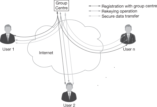
Figure 8.3 Centralized key management scheme
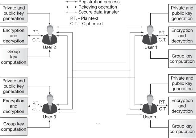
Figure 8.4 Distributed key management scheme
The three modules are private and public key generation, group key computation and encryption and decryption. Among the three modules, the first module private and public key generation is used for generating a private (secret) key and public key for each user based on some parameter. The second module, group key computation is used for computing a common GK for performing encryption and decryption. The third module encryption and decryption is used for providing secure group communication in the distributed key management scheme.
8.2.1 Key Generation
Key Generation process in secure multicast communication is responsible for generating the random keys to be assigned privately to the registered users. This process also computes GKs with respect to the public keys related under the same subgroup. An important issue in the maintenance of integrity is that generating the GK by the GC and making the members of the group to derive the GK without showing the secret key of individual members of the group. There are two types of techniques that are used for GK generation. In the first method, users are generating their own secret keys from which they compute a common GK which will be acting as a common shared secret key for a group of members. This method is called distributed key management scheme. In the second method, a trusted third party called GC generates the GK and distributes them to the group members in a secure way. This method is called centralized key management scheme. In both the schemes, several computations are necessary to compute the subgroup key and GKs. Moreover, both these schemes need storage for storing the public parameters and various key values used for computing the GK. According to Poovendran [4] and Mingyan Li [6], a key generation scheme should not suffer due to the computational complexities occurring because of integer factoring or the computation of discrete logarithms as present in the existing key generation schemes.
8.2.2 Key Distribution
Key distribution process in secure multicast communication is responsible for distributing the public keys and GKs to the registered users. Therefore, it is necessary to provide a registration facility using a special registration authority which can use the support of a GK distribution centre. This registration authority can send secret keys to all the members of the group when they complete the registration process. GKs can be distributed either by the GC to the participating members or the members themselves will be distributing the keys generated by them which are necessary for computing the GK. In a centralized key management scheme, the GK is distributed by the GC whereas in the distributed approach any one of the group members can provide support for distributing the GK.
8.2.3 Key Updating
Key updating is the process of changing the GK from time to time whenever a user join or leave the group. Key updating is also called key recovery. Key updating process in secure multicasting is used for group members to construct the original GK computed by a trusted third party called GC in the centralized key management scheme. On the other hand in distributed GK management, the key recovery process is used for group members to compute the GK which is based on the public values received from other group members. In both of these schemes, the members of the group should take minimum number of mathematical operations for recovering the newly generated or updated GK. Moreover, the key recovery process should take minimum number of parameters for recovering the common GK whenever there is a change in the group membership.
8.3 Diffie–Hellman Key Exchange
Diffie–Hellman key exchange is a key exchange algorithm applied to resolve the following dilemma. Alice and Bob desire to compute a shared secret key for encrypting a message using symmetric cipher method. In order to compute the shared secret key in an insecure channel, they need to exchange some public parameters from which, they are allowed to compute a common shared secret key. In such a scenario, the adversary Eve, may follow the public information that are exchanged between Alice and Bob from which Eve may try find the shared secret key. Therefore, Alice and Bob should compute the shared secret key without knowing it to Eve. Diffie and Hellman solved this problem by utilizing the difficulty of computing the discrete logarithms [8]. This algorithm was developed in 1977 and it was named as Diffie–Hellman key exchange algorithm. The following subsection gives an overall idea about Diffie–Hellman key exchange algorithm.
8.3.1 Diffie–Hellman Key Exchange Algorithm
Step 1: Initially, Alice and Bob select a large prime number p.
Step 2: Choose a primitive root of a prime number p. The primitive root of a prime number p is a number whose power generates distinct integers from 0 to  . For example, If k is a primitive root of a prime number p, then calculation of

generates distinct integers ranges from 0 to  The primitive root of a prime number is also called generator. The primitive root is used to generate the public keys of the users. The main reason behind the selection of primitive root is that no two users can create the same public key. Alice and Bob post the values such as a prime number p and a primitive root k of p to the public knowledge.
Step 3: In this process, Alice selects a secret integer A less than p and then computes a public key C using the prime number p and the primitive root k.

Step 4: Likewise, Bob selects a secret integer B less than p which is independent of A and then computes the public key D.

Step 5: Next, these computed public key values are exchanged between Alice and Bob in such a way that Alice transmits C to Bob and Bob transmits D to Alice. Note that the adversary Eve can also take the values of C and D, since they are transmitted over the insecure communication channel.
Step 6: Alice calculates the shared secret key one  using the secret integer A and public key of Bob as mentioned below:

Step 7: In a similar way, Bob calculates the shared secret key two  using the secret integer B and public key of Alice as mentioned below:

The two values  and computed by Alice and Bob are equal.
Theorem 8.1:
Show that the shared secret keys are identical.
Proof:


 (by the rules of modular arithmetic)

=
= 
From Theorem 8.1, it is evident that  and thus the shared secret key values are equal. The complete steps of Diffie–Hellman key exchange are represented in an illustrative manner as shown in Figure 8.5. In this figure, Alice wishes to establish a link with Bob and utilizes the shared secret key to encrypt the messages transmitted through that connection to make message communication confidentially. In order to do that, Alice and Bob choose distinct one-time secret integer (public keys) A, B and then calculate C and D, respectively. Alice sends C to Bob and Bob responds to send D to Alice. Both Alice and Bob can now calculate the shared secret key.
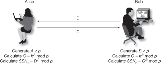
Figure 8.5 Diffie–Hellman key exchange
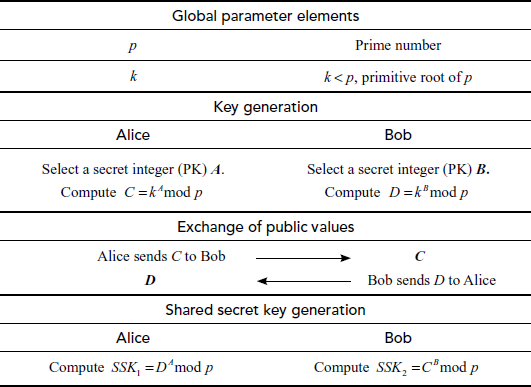
The summary of Diffie–Hellman key exchange algorithm is shown in Table 8.1. From the process indicated in Table 8.1, it is clear that Alice and Bob compute their own shared secret key by following the required steps. It is to be noted that the computed shared secret keys are identical.
Table 8.1 Summary of Diffie–Hellman key exchange algorithm
Example 8.1:
Alice and Bob use the Diffie–Hellman key exchange technique with a common prime number 11 and a primitive root of 2. If Alice and Bob choose distinct secret integers as 9 and 3, respectively, then compute the shared secret key.
Solution
Alice computes  = 6
= 6
Bob computes  = 8
= 8
After that, Alice and Bob exchange public keys (C and D), thereby each of them can individually compute the shared secret key:
A computes  = 7
= 7
B computes  = 7
= 7
8.3.2 Discrete Logarithms
Consider Equation (8.1) mentioned below.
 (8.1)
(8.1)
In this equation, assume that A, k and p are known values. With reference to this context, the process of finding the unknown value of n, when A, k and p values are known is called the discrete logarithm problem. Here, n is the discrete log of A which is indicated as shown in Equation (8.2).
 (8.2)
(8.2)
Since k is the primitive root of the prime number p, we can say n is the discrete log of A with respect to the primitive root k. If k is not a primitive root of A, then it is not feasible to find the discrete logarithm n for the values of A since we would not obtain distinct values. For the known values of A, k and p, it would be possible to find the value of n by brute-force attack only for small numbers. However, it is impractical to determine the value of n for larger number. In the next section, we discuss some methods for computing discrete log problem.
8.4 Computing Discrete Logarithms
There are various methods for computing the discrete log problem. Among the various methods, we have explained baby step, giant step and index calculus in this book.
8.4.1 Baby Step, Giant Step
Let us consider the prime number p and the primitive root  is a random secret integer less than p which is kept secret. Therefore

In order to find exponent , first compute
  as shown in Equation (8.3).
 (8.3)
(8.3)
Then, compute  for some
  . Then, compute the values as shown in Equation (8.4).

 (8.4)
(8.4)
From Equation (8.4), the computation of  and
and  values result in finding the value of
 (exponent), since
 .
.
Giant step: The process of computing the values of  and storing it in a table for
  = 0,
= 0,  values is called giant step.
Baby step: The process of computing the values of  for
for  =
=  and storing it in another table is called baby step.
Finally, by comparing both the tables, the value of  can be obtained.
Example 8.2:
Let  . Find the discrete log value A using baby step, giant step process.
Solution
 = 4
= 4
Compute the value  =
=  and
and  =
= 
Table 8.2 Computation of i, j values
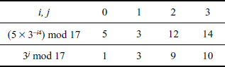
From Table 8.2, it is clear that when  , it results in same value (3) for baby step as well as for giant step. Hence, we can conclude that the value of
  and
and  . Using the above calculated values, the exponent
  can be easily computed as shown in Equation (8.5).
 = (1 × 4) + 1 = 5(8.5)
Therefore . The value of
  can be verified by substituting it in the given equation as follows:


Thus, the value of  obtained using baby step and giant step is acceptable.
8.4.2 Index Calculus
Index calculus is a process of computing values of the discrete log based on the index value.
- Let
 be the prime number and
  be the primitive root of
  .
. - For the given value of
 , it is feasible to determine a discrete log value
  of
of  using the index calculus method.
 - In order to do this, randomly select
 and then compute
  until the
  value is completely factored over prime numbers.
 - Hence,
 , where ai is prime powers and pi is prime numbers, 0 ≤ i ≤ n - 1.
 - Therefore, the discrete log value
 of
of  is simply obtained as shown in Equation (8.6).
 (8.6)
(8.6)
Example 8.3:
Let . Find the discrete log value of A using index calculus method.
- Randomly select the value of
 and then compute
  until the
  value is completely factored.
 - If
 then
then


For
 which is not factored completely with respect to prime numbers.
 - If
 then
then


For
 which is factored as prime numbers. Therefore, we can consider the value of
  is 2.
is 2. - Therefore, the discrete log value
 of
of  can be computed byx


8.5 Man-In-The-Middle Attack
The Diffie–Hellman exchange algorithm can be easily attacked using man-in-the-middle (MITM) attack. In order to do this, an attacker may begin two distinct key exchanges in this attack to Alice and Bob in such a way that they believe that it comes from reliable source (Alice/Bob). For doing this, initially the attacker intercepts the public key value sent by Alice to Bob and transmits the attackers public key value to Alice. Similarly, when Bob sends his public key value, the attacker replies with attackers public key value in such a way that the message comes from Alice. After sending the public key value of attacker to both Alice and Bob, they compute different shared secret key  and
and  . These two shared secret key values computed by Alice and Bob are not same and hence
  .
.
After computing SSK1, Alice encrypts the message using SSK1. This encrypted message is sent to Bob. Meanwhile, an attacker intercepts the encrypted message and decrypts it using the SSK1. The attacker can compute SSK1 using the public key received from Alice and secret integer (Z) of attacker SSK1 = kAZ mod p. After decrypting it, the attacker encrypts some other message using SSK2 = kBZ mod p, which can be decrypted by Bob. In this attack, the attacker reads the message sent by one party and modifies them with the suitable key and sends them to the other party. Note that the attacker must be present in the middle during the transmission of messages every time between Alice and Bob. If the attacker is sometimes absent, his earlier presence is then disclosed to Alice and Bob in such a way that they cannot decrypt the messages since  and hence they will recognize that all of their previous private communications had been intercepted, decrypted and modified by an attacker in the channel. The MITM attack is depicted in Figure 8.6.
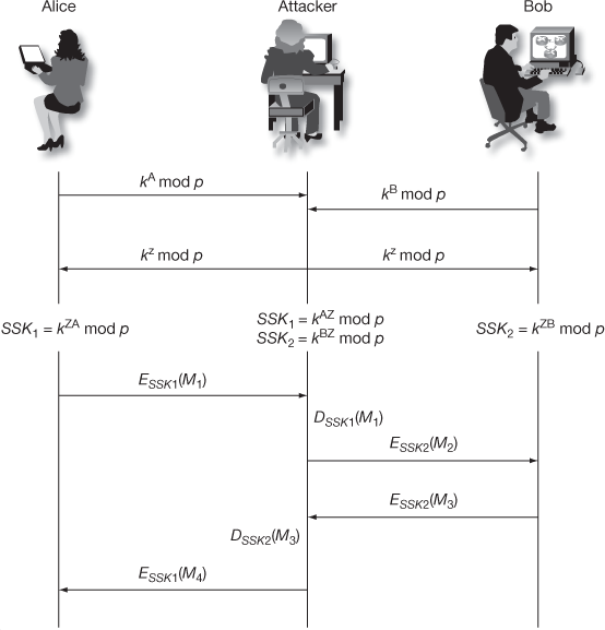
Figure 8.6 Man-in-the-middle attack
MITM Procedure
- An attacker chooses an exponent Z as secret key.
- Attacker intercepts
 and
and  which are sent by Alice and Bob.
 - Attacker transmitts
 to both Alice and Bob, from that transmission Alice thinks that Bob has received
  and Bob thinks that Alice has received
  .
. - Attacker computes
 and
and  . Similarly, Alice and Bob compute
  and
and  respectively. In this case, both Alice and Bob do not realize that the attacker is in the middle.
 - When Alice encrypts a message with
 and sends it to Bob, attacker intercepts the encrypted message in the middle, decrypts it and then re-encrypts it with
  and forwards it to Bob.
 - After receiving the message, Bob decrypts the message with
 and thinks that the message was sent by Alice and gives the reply to Alice. Here, Bob does not know that the communication was attacked and at the same time the attacker gets pleasure from reading Alice’s message.
8.6 JAVA Implementation of Diffie–Hellman Key Exchange Algorithm
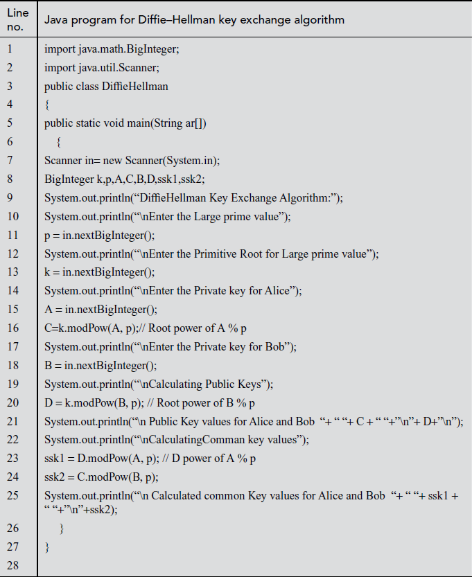
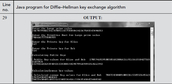
In the above program, there is a shared secret key computation module that can be used in Alice and Bob side. In line numbers 16 and 18, the public key of Alice and Bob is calculated. In line numbers 23–24, the common shared secret key of Alice and Bob is calculated.
8.7 Secure Multicast Communication Based on Diffie–Hellman Key Exchange
In this section, we discuss an efficient Diffie–Hellman key exchange-based GK computation protocol for providing secure data transmission among a group of users [1]. This GK computation protocol works in the distributed key management scheme that supports two major operations, namely, user joining and user leaving for managing group memberships.
8.7.1 Introduction
This key exchange works in three phases. The first phase is the group initialization, where the multiplicative group is created. In the second phase of member initial join, the members send the joining request to the existing group members and obtain all the necessary keys for participation. The final phase of rekeying deals with all the operations to be performed after a member leaves/joins the group (providing forward/backward secrecy).
8.7.1.1 Group Initialization
Initially, the group members select a large prime number p. This value, p helps in defining a multiplicative group zp* and a secure one-way hash function H(.). The defined function, H(.) is a hash function defined from  , where x and y are non-identity elements of zp*. Since, the function H(.) is a one-way hash function, x is computationally difficult to determine from the given function
 and y.
8.7.1.2 Member Initial Join
Whenever a new user  is authorized to join in a group for the first time, the user selects a secret key
  from the group zp*, which is known only to the user
  who computes the Euler’s totient function value of it. The result is represented as
  which is used as a component in secure one-way hash function. Next, it computes the public key by using the parameter p (group size) and a value y which is selected from the group zp* such that
  . New user i sends join request along with its public key to the entire remaining user’s and also gets all users public key for computing the GK.
8.7.1.3 Rekeying
Whenever some new members join or some old members leave the group, the existing group members need to compute the new GK in such a way that all the existing members should have the same GK. In such computational scenario, the new GK should be computed in minimal computation time. During the key computation process, one node will be designated as a support node, where this node will usually be located nearest to the member leave/join node. If the tree is unbalanced, the support node will be located in the shallowest right most area as shown in Figure 8.8. If the tree is a balanced one, any node can become a support node.
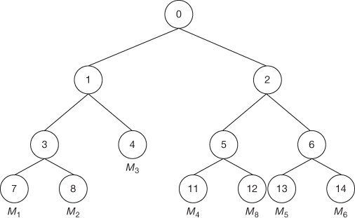
Figure 8.8 Binary tree key management scheme
8.7.2 Key Computation Protocol
In distributed key management environment, the GC is not responsible for computing GK and SGK. Each member is generating GK via each user’s and internal nodes public key. Each member Mi holds a pairs of keys called secret key and public key. The notations used to represent the secret and public key are  (the secret key of member Mi ) and
  (the public key of member Mi), which will remain valid from the time Mi joins until it leaves. With the help of each user’s public key, a GK is computed when a member join or leave from the service. GK can be used to encrypt and decrypt the data that is shared between the group members.
In this key management scheme, a binary key tree is formed in which each node v represents a secret (private) key  and a public key
  . Public key can be calculated by using the function
  where
where  and
and  are public parameters for that group. The function
  represents Euler’s totient value of the secret key
  . Every member holds the secret keys along the key path from his leaf node to the root node. For simplicity, we assume that each member knows the public keys of all other group members who are in the key tree. Initially, each member randomly selects the secret key of a leaf node. The secret key of a non-leaf node
  can be generated as shown in Figure 8.7
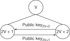
Figure 8.7 Calculation of a node value
Since the member 2v + 1 knows the public key of member 2v + 2, the member 2v + 1 can calculate the value of node  by,
by,
 (8.7)
(8.7)
Similarly member 2v + 2 knows the public key of 2v + 1, this member can compute the node value by,
 (8.8)
(8.8)
The computed values shown in Equations (8.7) and (8.8) should be equal. Each user generates GK via all others and intermediate nodes public key. For example, in Figure 8.8, the member M1 can generate GK via the following steps:
- Using K7 and public key8, the node key K3 is calculated.
- After computing K3, the public key public key4 and K3 are used to calculate the node key K1.
- Finally, using K1 and public key2, the root key K0 (GK) is calculated.
The same procedure is used by all other members of the group for computing the GK when there is a change in group membership.
8.7.2.1 Member Joins
Consider a binary tree depicted in Figure 8.9(a) that has 6 members {M1, M2…M6}. The new member M8 initiates the protocol by broadcasting a join request message that contains its own public key8. This message is distinct from any JOIN messages generated by the underlying communication system. Each current member receives this message and first determines the insertion point in the tree. When finding the insertion point, it should not increase the height of the key tree. Hence, the appropriate place for choosing the insertion point is to find a node which is located in a small depth. The member who is located in that insertion point becomes a support node. Otherwise, if the key tree is fully balanced, any of the leaf nodes can act as support node to insert the new member in the key tree structure.
The support node has to find the insertion point for the new member. After finding the insertion point, the support node creates a new intermediate node, a new member node, and promotes the new intermediate node to be the parent of both the insertion node and the new member node. The support node is responsible for updating all the internal node keys located in the path from leaf node to the root node. After the updating process, the support node broadcasts the public key of updated key nodes to essential group members. On reception of the public keys, all other members in the key tree update their GK. Only the required public keys for the computation of GK are sent to the group members, since all the other keys are already known to them and it might appear to increase the network traffic. Figures 8.9(a) and (b) illustrate the case of member join/member leave. Suppose if member M8 wants to join in this group, then the keys from the leaf node to the root node must be updated in order to provide backward secrecy. First, the new joining user broadcasts its public key12 on joining.
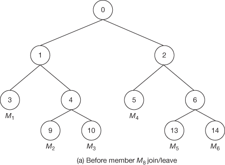
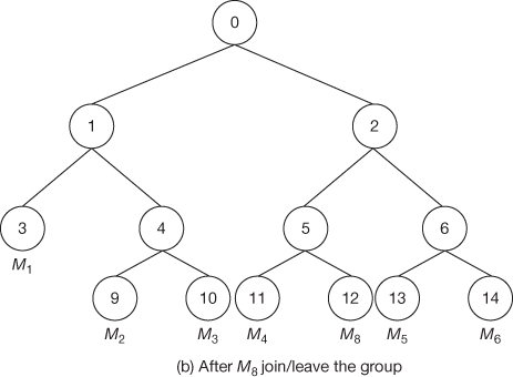
Figure 8.9 Member join/leave case
After joining, the support node becomes the responsible node to update the keys that are located in its path. It rekeys K5, K2, and K0 and then broadcasts the public keys PK5 and PK2. The members M1, M2 and M3 compute K0 from the given PK2. Members M5 and M6 compute K2, K0 from the given public key PK5.
8.7.2.2 Member Leaves
Assume that there are n members in the group currently where member Mn leaves the group. Now, the support node becomes a responsible node to update the GK and to broadcast all the required public keys in the key tree. When a member leaves from the tree, its immediate left or right node will be uplifted higher by one level to reduce the number of keys to be updated by the support node. During the member leave operation, all the keys from the leaf node to the root node must be updated in order to prevent the access of future data by the left members from the group. This provides forward secrecy. If member M8 wants to depart from the service, the internal node keys K5, K2 and K0 must be renewed as shown in Figures 8.9(b) and Figure 8.9(a). During the update phase, the support node M4 becomes a responsible node to rekey the secret keys K2 and K0 and broadcasts the public keys PK2 and PK5. The members M1, M2 and M3 compute K0 from the given PK2. Members M5 and M6 compute K2, K0 from the given public key PK5.
8.8 Computation-Efficient Secure Multicast Key Management Based on Greatest Common Divisor
In this work, a new GCD (greatest common divisor)-based key distribution protocol that focuses on two dimensions [2] is introduced. The first dimension deals with the reduction of computation complexity which is achieved in this protocol by performing less number of multiplication operations during the key updating process. The second dimension aims at reducing the amount of information stored in the GC and group members while performing the updating operation in the key content.
8.8.1 Introduction
This protocol works in three phases. The first phase is the GC initialization, where a multiplicative group is created at GC. In the second phase called member initial join phase, where the members send join requests to the GC and obtain all the necessary keys for participation through secure channel. The final phase of this protocol is known as ‘member leave’ that deals with all the operations to be performed after a member leaves from the group (providing forward secrecy). This work mainly concentrates on the third phase of ‘member leave’ phase because the computation time is extremely large in most of the existing systems for providing forward secrecy. This is extremely a great challenge in most of the multimedia multicast applications.
8.8.1.1 GC Initialization
Initially, the GC selects a large prime number  and
and  , where
  and
and  . The value,
  helps in defining a multiplicative group zp* and
  is used to fix a threshold value
  , where
 The value
  is a random element from the group zp* and hence when
  value increases, the value of
  also increases.
8.8.1.2 Member Initial Join
Whenever a new user i is authorized to join the multicast group for the first time, the GC sends (using a secure unicast) a secret key  which is known only to the user
  and GC.
  is a random element in zp* and the necessary condition is that all
  values are greater than
  . If this condition is not satisfied, then the value of
  must be adjusted so that it is possible to select
  >
> . Using this
  , the encrypted SGK
  and a GK
  are given for that user
  which will be kept in the user
  database. The following steps describe the key updating process used for member join operation at the GC.
- Initially, GC selects a random element
 from zp*.
 - GC now computes the GK
 .
. - The GC calculates

- The GC computes GCD value of
 by using extended Euclidian algorithm described in Ref. [3] from which it finds
  such that
- The GC multicasts
 to the group members.
Upon receiving all the above information  from the GC, an authorized user
  of the current group executes the following steps to obtain the new GK
 .
.
- Computes x1 using the relation x mod Ki = x1.
- Computes
 using x1−1 mod Ki = μ.
 - Performs the following operation to find the shared secret key.

The
 obtained in this way must be equal to the
  computed in Step 2 used in GC.
Security
Computing the newly updated  in the proposed scheme depends on the method used to calculate the members secret key
  in a particular time period. In this scheme, the GC distributes the elements
  to the group members through multicast communication. Hence, an attacker will try to capture all the distributed elements and by using these elements, the attacker can try to find the value of μ. This
  can be computed only by using the user’s secret key
  . If the attacker is not an active adversary (i.e. not a previous member of the multicast group), the attacker can use brute-force attack to learn about any one member’s secret key
  . If the size of
  is
is  bits, then the attacker has to use the total number of trial of
 . The time taken to derive
  can be increased by choosing the large
  for each user’s secret key. In this work, the size of
  must be 64 bits or 128 bits. If the time required to perform one attempt using brute-force attack is 1 us, then the total time required will be 263 us = 292471 years. Therefore, when large-size
  is used, it is not possible to find the value of
  and hence
  cannot be computed by an adversary.
8.8.1.3 Member Leave
Whenever some new members wish to join or some old members wish to leave the multicast group, the GC needs to distribute a new GK to all the current members in a secure way with minimal computation time. When a new member joins the service, it is easy to communicate the new GK with the help of the old GK. Since the old GK is not known to the new user, the newly joining user cannot view the past communications. This provides backward secrecy. Member leave operation is completely different from member join operation. In member leave operation, when a member leaves from the group, the GC must avoid the use of old GK/SGK to encrypt new GK/SGK. Since old member knows old GK/SGK, it is necessary to use each user’s secret key to perform rekeying operation when a member departs from the services. In the existing key management approaches [4–5], this process increases GC’s computation time, because the number of multiplications operations to be done in the key updation is more. In this key distribution scheme, the computation times are equalized for member join and leave operations. Therefore, this work aims at reducing the computation time by decreasing the number of multiplication operations to be carried out.
8.8.2 Clustered Tree-based Key Management Scheme
Scalability can be achieved in this key distribution approach by applying this scheme in a clustered tree-based key management scheme to update the GK and SGK. Figure 8.10 shows a cluster tree in which, the root is the GK, leaf nodes are individual keys, and the intermediate level is SGK. The tree shown in Figure 8.10 consists of only three levels. The lowest level (0th level) is the GK. The next higher level (1st level) contains the shared secret keys,  where i = 1, 2, …, n. The last level (2nd level) is the users level, where M number of users are grouped into
  clusters,
  . Each cluster is attached to the upper level (1st level) node and in turn with the GK node. When the number of joining users exceeds the cluster size, a new node is created from the root to form the second cluster. The number of clusters formed is based on the cluster size
  which is fixed by GC and the number of joining users. If the cluster tree-based key management consists of
  number of users
  ,
, …
… and each cluster size is of size M, then there will be
  clusters. In this cluster tree-based key management scheme, updating is necessary for each rekeying operation used for member leave and member join operations. For example, if a member M10 in cluster 2 from the Figure 8.10 leaves from the group, then the keys on the path from his leaf node to the tree’s root node must be changed. Hence, only the keys
  will become invalid. Therefore, these two keys must be updated.
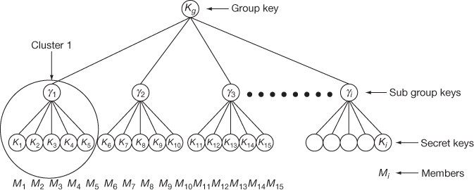
Figure 8.10 Clustered tree-based key management with cluster size M = 5 and number of users = N
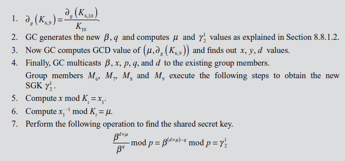
After updating the above SGK successfully, GC has to use the second approach in order to update the GK  using a different procedure as explained below. The new GK
  is used to encrypt the data. For updating the GK, GC generates a new GK from
 , with a condition that the new GK
  <
<  . If this condition is not satisfied, then append a value 1 in front of
  in order to make
  is a greater value than
  as used in Ref. [4]. Every time when a new cluster is created, its corresponding SGK is multiplied with all others SGK and the result is stored in to a temporary variable X. Therefore, whenever a new cluster is created, only the new
  of the newly created cluster is multiplied with the value X which is stored in GC. Hence, only one multiplication is needed for updating the GK. Similarly, when an existing cluster is completely deleted, X is divided by the corresponding
  value and hence only one division is necessary for updating the GK. In order to understand the key updation when a single member leaves a group, consider an example using Figure 8.10 where let only one member
  leaves from the cluster (cluster 2). In this case,
  must be updated and let the updated
  be represented as
  . In order to update
  , the GC must divide X by
  first and then the result must be multiplied with the newly computed
  and the final result is stored in to the variable X. This X is added with the newly generated GK
  to obtain
  and the rekeying message is formed by using the equation
 . In this way, member leave operations are handled effectively by reducing the number of multiplication/divisions.
The resultant value  is broadcast to the remaining members of the group. The members of the group can recover the updated GK with the help of
  using the relation,

The key strength of this algorithm is that the scalability increases sufficiently. The number of keys to be used by the GC and group members is reduced. Each user has to store three keys, since the tree described in the proposed algorithm has three levels. If the number of clusters is  and each cluster consists of
  users, then the storage complexity of GC is
  , where
  is used to denote the total number of
  and
and  used for every cluster that are stored in GC. The computation complexity of the GC and group members is 3, which means that they will perform only three mathematical operations such as multiplication, multiplicative inverse and GCD.
8.9 JAVA Implementation of Secure Multicast Key Management Based on GCD
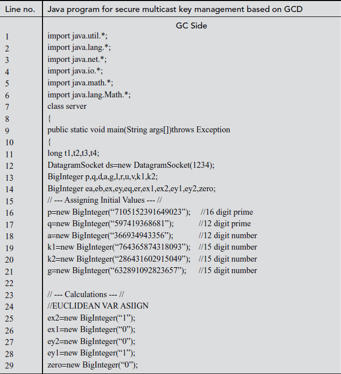


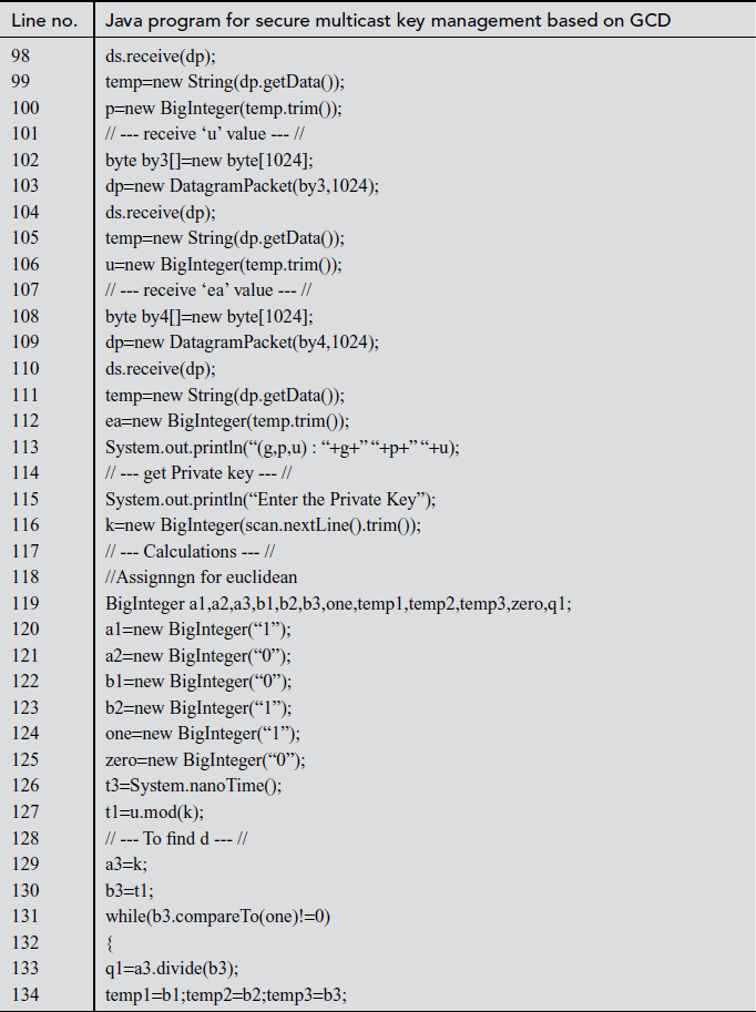
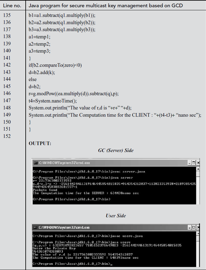
In the above program in line numbers between 16 to 21, necessary variables for the program are assigned with values in the GC side. Line numbers between 36 and 49 represent the extended Euclidian operation (encryption) that is essential for this approach. After this, the essential parameters are sent to the client for the computation of GK using datagram packet which are represented in line numbers between 53 and 61. In the user’s side, q, g, p, u and ea are received by the client that represented in line numbers between 86 and 110. Line numbers between 131 and 145 represent the extended Euclidian operation performed by the client. Line numbers between 145 and 146 represent the decryption operation performed by the client.
Key Terms
Baby step
Backward secrecy
Binary key tree
Centralized key management
Clustered tree approach
Cluster size
Computation complexity
Diffie–Hellman key exchange
Discrete logarithms
Distinct integers
Distinct key exchanges
Distributed key management
Dynamic groups
Euler’s totient value
Extended Euclidian algorithm
Forward secrecy
Generator
Giant step
Greatest common divisor
Group centre
Group initialization
Group key
IGMP
Index calculus
Key computation protocol
Key distribution
Key generation
Key management
Key recovery
Key updating
Man-in-the-middle attack
Member join or leave
Multicast communication
One-way hash function
Primitive root
Private key
Public key values
Scalability
Secret integer
Secure multicast communication
Shallowest rightmost node
Shared secret key
Static groups
Subgroup key
Support node
Summary
- Multicast communication is a type of communication in which one sender is sending a common message to a group of receivers.
- In static group communication, membership of the group is predetermined and does not change during the communication.
- In a dynamic group communication, members can either join or leave from the service at any time.
- Preventing new members from having access to previous data is called backward secrecy.
- Preventing existing members who do not have further access to the multicast communication during member leave is called forward secrecy.
- The backward and forward secrecy can be achieved only through the use of effective key management schemes.
- The process of generating, distributing and managing keying materials to secure the group communication is called key management.
- Key managements schemes are classified into centralized and distributed schemes.
- Key generation process in secure multicast communication is responsible for generating the random keys to be assigned privately to the registered users.
- Key distribution process in secure multicast communication is responsible for distributing the public keys and GKs to the registered users.
- Key recovery process in secure multicasting is used for group members to construct the original GK computed by a trusted third party called GC in the centralized key management scheme.
- Diffie–Hellman key exchange is a key exchange algorithm in which shared secret key is securely communicated by utilizing the difficulty of computing the discrete logarithms.
- A shared secret key is a key used for encrypting a message using symmetric cipher methods.
- The primitive root of a prime number
 is a number whose power generates distinct integers from 0 to
  .
. - In Diffie–Hellman key exchange, the computed shared secret keys are identical.
- The process of finding the unknown value from the known values using logarithms is called the discrete logarithm problem.
- The process of computing the values of
 and storing it in a table for
  =
=  values is called giant step.
 - The process of computing the values of
 for
for  =
=  and storing it in another table is called baby step.
 - Index calculus is a process of computing values of the discrete log based on the index value.
- The Diffie–Hellman exchange algorithm can be easily attacked using MITM attack.
- In MITM attack, an attacker may begin with two distinct key exchanges in such a way that Alice and Bob believe that it comes from a reliable source.
- In MITM attack, an attacker must be present in the middle during the transmission of messages every time between Alice and Bob else the earlier presence of an attacker is then disclosed to Alice and Bob.
- Diffie–Hellman key exchange-based GK computation protocol works in a distributed key management scheme where the two major operations are member joining and leaving.
- Diffie–Hellman key exchange-based GK computation protocol has three phases, namely group initialization, member initial join and rekeying.
- In the distributed key management environment, the GC is not responsible for computing GK and SGK. Each member generates GK via each user’s and internal nodes public key.
- In Diffie–Hellman key exchange-based GK computation protocol, keys are derived from bottom (leaf) of the tree to the top (root) of the tree.
- GCD-based key distribution protocol deals with the reduction of computation complexity and the amount of information stored in the GC and group members.
- In GCD-based key distribution protocol, GC uses extended Euclidian algorithm for computing GCD value.
- In GCD-based key distribution protocol, scalability can be achieved by applying clustered tree-based key management scheme.
- In clustered tree-based key management scheme, root node is the GK and leaf nodes are individual keys.
- Clustered tree-based key management scheme can have a maximum of three levels starting from 0th level to 2nd level.
- The key strength of GCD-based key distribution protocol is that the scalability increases sufficiently and each user has to store only three keys since clustered tree has three levels.
Review Questions
- Differentiate centralized and distributed key management schemes.
- Draw the architecture of centralized key management and explain it in detail.
- Explain about Diffie–Hellman algorithm with a suitable example.
- Prove that 2 is a primitive root of the prime number 11.
- Find whether 3 is a primitive root of the prime number 11.
- Compute the common shared secret key for the prime number p = 181 and primitive root k = 127. Consider the secret integer chosen by Alice is 48 and the secret integer chosen by Bob is 58.
- Find the value of Alice’s secret integer A from her PK value C = 6511 using the baby step, giant step method, if p = 12347 and primitive root k = 8833.
- Find the value of Alice’s secret integer A from her public key value C = 6989 using the index calculus method, if p = 12347 and primitive root k = 11920.
- Consider a Diffie–Hellman scheme with a common prime number p = 13, and a primitive root k = 7.
(a) Show that 7 is a primitive root of 13.
(b) If Alice has a public key C = 5, what is Alice’s private key A?
(c) If Bob has a public key D = 12, what is Bob’s private key B?
- Explain about group Diffie–Hellman key management scheme in detail.
- Explain in detail about computation-efficient secure multicast key management which is based on GCD.
- Explain about user leave operation performed on a clustered tree-based key management scheme.
References
- P. Vijayakumar, S. Bose and A. Kannan (2011), ‘Error Detection and Correction for Distributed Group Key Agreement Protocol’, International Journal of Network Security & Its Applications, 3(5): 257–270.
- P. Vijayakumar, S. Bose and A. Kannan (2013), ‘Centralized Key Distribution Protocol using the Greatest Common Divisor Method’, Computers & Mathematics with Applications, Elsevier, 65(9): 1360–1368.
- Wade Trappe and Lawrence C. Washington (2007), Introduction to Cryptography with Coding Theory (India: Pearson Education, Second Edition), pp. 66–70.
- Wade Trappe, Jie Song, Radha Poovendran and Ray Liu K J (2003), ‘Key Management and Distribution for Secure Multimedia Multicast’, IEEE Transactions on Multimedia, 5(4): 544–557.
- Lihao Xu and Cheng Huang (2008), ‘Computation-efficient multicast key distribution’, IEEE Transactions on Parallel and Distributed Systems, 19(5): 1–10.
- Mingyan Li, Iordanis Koutsopoulos and Radha Poovendran (2010), ‘Optimal Jamming Attack Strategies and Network Defense Policies in Wireless Sensor Networks’, IEEE Transactions on Mobile Computing, 9(8): 1119–1133.
- Kevin Hastings, Nick Nechita and Aliant (2000), ‘Challenges and Opportunities of Delivering IP-Based Residential Television Services’, IEEE Communications Magazine, 38(11): 86–92.
- http://www.nku.edu/~christensen/092mat483%20DH%20key%20exchange.pdf