Table of Contents for
Cryptography and Network Security
 Cryptography and Network Security
Published by
Pearson Education India, 2016
Cryptography and Network Security
Published by
Pearson Education India, 2016
- Cover
- Title Page
- Engineering Chemistry
- Contents
- Foreword - 1
- Foreword - 2
- Preface
- Acknowledgements
- CHAPTER 1 Cryptography
- CHAPTER 2 Mathematics of Modern Cryptography
- CHAPTER 3 Classical Encryption Techniques
- CHAPTER 4 Data Encryption Standard
- Chapter 5 Secure Block Cipher and Stream Cipher Technique
- Chapter 6 Advanced Encryption Standard (AES)187
- Chapter 7 Public Key Cryptosystem
- Chapter 8 Key Management and Key Distribution
- Chapter 9 Elliptic Curve Cryptography
- Chapter 10 Authentication Techniques
- Chapter 11 Digital Signature
- Chapter 12 Authentication Applications
- Chapter 13 Application Layer Security
- Chapter 14 Transport Layer Security
- Chapter 15 IP Security
- Chapter 16 System Security
- Appendix: Frequently Asked University Questions with Solutions
- Basic Mechanical Engineering
5.1 Need for Double DES and Triple DES
As per DES algorithm, the key size is constrained to only 56-bit thereby brute-force attack can be easily performed in a simple manner. Moreover, linear and differential cryptanalysis illustrates that DES is not an efficient algorithm in terms of providing security to the given plaintext. Therefore, an efficient algorithm was required in compensation with DES algorithm at that point of time to serve many secure Internet protocols. To handle this type of scenario, double DES was introduced by the national institute of standards and technology (NIST). In double DES, two symmetric keys were used for encryption and decryption, however double DES also had some limitations. With regard to this context, triple DES was introduced in the year 1999 by a team led by Walter Tuchman who was working at IBM. Triple DES resolved all the limitations of double DES by using three symmetric keys as well as two symmetric keys. Moreover, triple DES is extensively used in many of the Internet protocols in today’s environment. A brief explanation of double DES and triple DES is given below.
5.2 Double DES
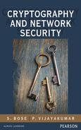
Using DES twice in a row is called double DES. During encryption, double DES takes 64-bit plaintext and 112-bit key as inputs to produce 64-bit ciphertext as output. During decryption, DES encryption operation is performed in inverse by taking 64-bit ciphertext and 112-bit key as input to produce 64-bit plaintext as output. The encryption and decryption of double DES can be expressed as shown in Equations (5.1) and (5.2).
 (5.1)
(5.1)
 (5.2)
(5.2)
where,
 and
and  denote DES encryption using k1 (56-bit) and k2 (56-bit) keys.
 and
and  denote DES decryption using k1 (56-bit) and k2 (56-bit) keys.
The encryption process of double can also be expressed diagrammatically as shown in Figure 5.1. From Figure 5.1, it is clear that an attacker must know 112-bit key for breaking double DES and thus double DES prevents brute-force attack to a greater extent. However, double DES can be easily attacked using meet-in-the-middle attack [1]. The attacking scenario of double DES using meet-in-the-middle attack is briefly explained below.
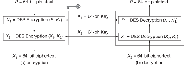
Figure 5.1 Double DES
5.2.1 Meet-in-the-Middle Attack
This type of attack requires some known plaintext and ciphertext pairs. Therefore, plaintext  and the corresponding ciphertext
  (obtained using double DES) are assumed in this type of attack. The objective of this attack is that, when pairs
  and
and  are known, then the respective keys k1 and k2 for encryption and decryption process can be found. Meet-in-the-middle attack finds the exact key values k1 and k2 and thus double DES becomes a weak algorithm.
5.2.2 Attacking Scenario
By considering Equations (5.1) and (5.2), initially  and
and  are assumed. Now plaintext
  is encrypted with all
  possible keys k1 and the results of encryption are stored in a storage area (table). Then, decrypt
  using all
  possible keys k2 and the results of decryption are stored in a storage area. After this process, for each result, check for a match as shown in Equation (5.3).
 (5.3)
(5.3)
If there is match as shown in Equation (5.3), then try for another pair . Continue the same process as mentioned above. Finally, if there is also match for the new pair
 , then it can be concluded that k1 and k2 are the actual keys that are used for double DES. The entire attacking scenario is clear in Table 5.1.
Table 5.1 Meet-in-the-middle attack
Example 5.1:
Assume the plaintext  = 3, k1 = 7 and k2 = 9. Initially, perform encryption and decryption using multiplication and division operations. Finally, perform meet-in-the-middle attack for the plaintext, ciphertext pair.
Encryption:
 = 3 × 7 = 21
 = 21 × 9 = 189
Decryption:
 = 189/9 = 21
 = 21/7 = 3
Now let us assume that the intruder knows plaintext, ciphertext pair = (3,189)
From Table 5.1, it is clear that the intermediate value gets matched for some k1 and k2 values with respect to the chosen plaintext, ciphertext pairs. Therefore, in this way, meet-in-the-middle attack can be performed for one pair of plaintext and ciphertext. In some cases, there will be a need for using two pairs of plaintext and ciphertext pairs also. Hence, 112-bit key (double DES) also provides same security as that of 56-bit key (DES).
5.3 Triple DES
The limitation of double DES is resolved using triple DES. The triple DES is an ANSI X9.17 and ISO 8732 standard [2] that uses three symmetric keys as well as two symmetric keys. During encryption, the triple DES takes 64-bit plaintext and 112/168-bit key as inputs to produce 64-bit ciphertext as output. During decryption, inverse DES operation is performed by taking 64-bit ciphertext and 112/168-bit key as input to produce 64-bit plaintext as output. The triple DES encryption and decryption using three symmetric keys are shown in Equations (5.4) and (5.5).
 (5.4)
(5.4)
 (5.5)
(5.5)
When three keys are used, the key size becomes 168 bits and therefore  combinations are required for brute-force attack, which is an unfeasible process. Triple DES encryption and decryption with two symmetric keys are shown in Equations (5.6) and (5.7).
 (5.6)
(5.6)
 (5.7)
(5.7)
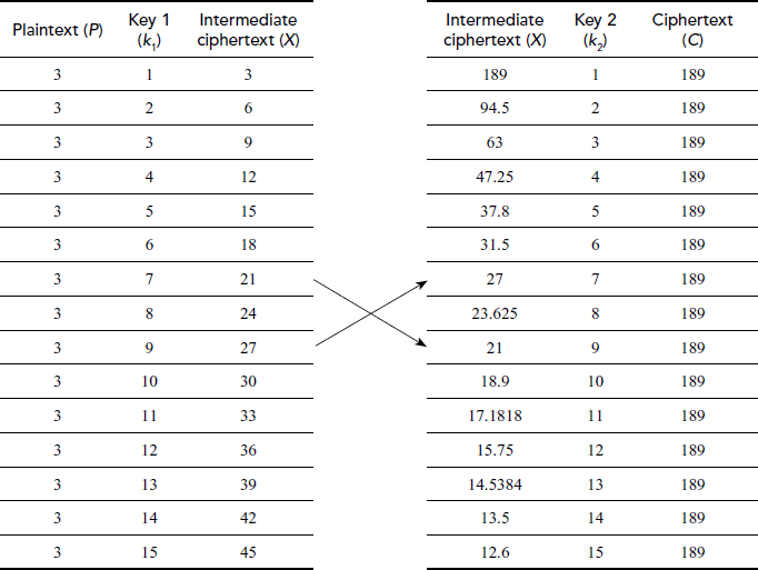
The entire structure of triple DES with three keys is shown in Figure 5.2. From Figure 5.2, it is evident that triple DES with three keys avoids man-in-the-middle attack even though known plaintext and ciphertext pairs are chosen. The reason is that three encryption/decryption processes are involved and hence intermediate value calculation becomes a tedious process and hence man-in-the-middle attack is not possible. The triple DES with two keys is shown in Figure 5.3. The triple DES is preserved from any of the practically known attacks [3]. Exclusively triple DES with three keys (168 bits) is used in some Internet applications such as PGP and S/MIME that provides greater security.
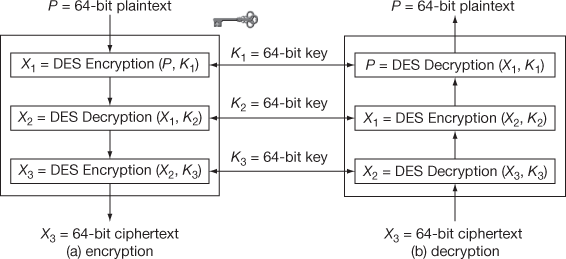
Figure 5.2 Triple DES with three keys
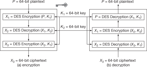
Figure 5.3 Triple DES with two keys
5.4 Pseudo Random Number Generator
A pseudo random number generator (PRNG) is a function which is used to generate sequence random numbers using mathematical equation [4]. A PRNG is also known as a deterministic random bit generator (DRBG). A random number is a number which is generated based on some given input, whose outcome is impulsive, and it cannot be constantly reproduced. This random number is used as a key value in many cryptographic algorithms (RC-4, RSA, Diffie–Hellman, SSL, etc.) to perform encryption operation. The main purpose of generating the random numbers as the key value to perform encryption in cryptography is to increase the security. Moreover, the random numbers are generated in key distribution and authentication schemes. In addition to above, the random numbers help in computing private and public keys in many public key cryptosystem such as RSA and Diffie–Hellman. Various PRNGs are linear feedback shift registers, linear congruential generators, and blum blum shub (BSS) generator. Among the various PRNGs, linear feedback shift registers start from an arbitrary starting state using a seed value as explained in Chapter 3. From that starting state, many random numbers are generated subsequently without repetition up to some value. After that, the numbers are repeated. If the period of repetition is long, then it will provide more security. For example, in linear feedback shift register, if  then the maximum required number of states without repeating the random number is 24 – 1 = 15. The following explains linear congruential generators and BSS generator [5].
5.4.1 Linear Congruential Generator
In this scheme, the sequence of random numbers is generated using the following equation:

where,
 is the modulus
 is the multiplier
 is a constant
 is the initial seed value
In this equation, we have to give more importance in choosing the right values of n, a and  in order to make the random numbers not to repeat for a long period. For example, if
  and
and  , then it will generate only the two values {7, 1}. Hence, the period of repetition is 2. If
  and
and  , then all the 14 values are continuously generated from 2 to 14. So, we have to generate the right values of
  and
and  for creating a good random generator. One of the important limitations of this approach is that, it is easily breakable. If the attacker knows that the sender has used the linear congruential generator and any one of the random numbers is found, then all its subsequent random numbers can be easily found. Even if the parameters n, a and c are not known to the intruder, the attacker can guess the information about some random number to compute the future random numbers. Therefore, linear congruential generator is rarely used in cryptography applications.
5.4.2 Blum Blum Shub Generator
In this scheme, the encryption algorithm generates the random number as explained below:
- 1. Generate two prime numbers p and q. These two prime numbers are congruent to 3 mod 4.
- Next, compute
 .
. - Choose a random integer z which in relatively prime to n.
- After that, set the initial seed key value
 .
. - Then, for each random bit, it computes
 .
. - 6. The BSS generates a sequence of random bits r1, r2…, where
 is the least significant bit of
The PRNG is different from true random number generator (TRNG). The Vernam one-time pad uses TRNG, whereas RC-4 uses PRNG. The difference between the PRNG and TRNG is that the PRNG generates a random number as output that many eventually repeat. But, the period of repetition is long in TRNG. In TRNG, equal number of 1’s and 0’s will be available in the output random value. This many not be possible in the PRNG. Figure 5.4 shows the differences between PRNG, pseudo random function (PRF) and TRNG.
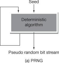
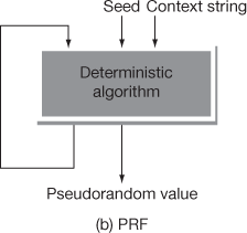
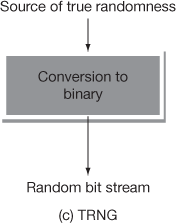
Figure 5.4 PRNG, PRF and TRNG
In PRNG, the truly generated random value is completely determined by a relatively small set of initial values. This is referred as PRNG’s seed. In contrast to PRNG, a random string is given along with the seed value in PRF. In PRF, all the generated outputs appear as random values, regardless of how the input seed value is chosen.
5.5 RC4
RC4 is a stream cipher which was invented by Ron Rivest in the year 1987. RC4 means ‘Rivest Cipher 4’ and it is also known as ‘Ron’s Code 4’ [6]. The RC4 cipher is the most widely used stream cipher. It is used in various applications that encrypts and decrypts a bit or byte of data at a time. For example, if 10 bytes of a file is to be transmitted, then RC4 has to generate 10 key streams for encrypting the plaintext bytes. Moreover, it is used by important protocols such as SSL, TSL, WPA and WEP, etc. because of its simplicity and efficiency. The RC4 is an efficient algorithm because it is 5 times faster than DES, 15 times faster than triple DES and 50 times faster than RC2.
5.5.1 Principle of RC4
The RC4 algorithm generates a pseudo random number which will be used as a key to encrypt the plaintext and to generate the corresponding ciphertext. The encryption and decryption are performed using an XOR operation in RC4. The major differences between the pseudo random number and true random number are discussed in Section 5.4. The pseudo random number is generated from a variable length key after performing the two algorithms, namely key scheduling algorithm (KSA) and pseudo random generation algorithm (PRGA). Among the two algorithms, KSA is used to generate the permutation array. PRGA is used to generate a pseudo random number which will be used as a key stream. To implement these two algorithms, initially a 256-byte array S is declared that contains a permutation of these 256 bytes. Next, two indexes i and j are used to point the elements in the S array.
5.5.2 The Key-scheduling Algorithm
In this algorithm, the S array is initialized. After that, the index values of S array are filled into S array. This process is shown in Figure 5.5.
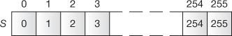
Figure 5.5 Array initialization
After filling the values, the values in the S array are permuted. In order to permute the values, the following steps are executed in the KSA.
- Compute

- Swap S[i] and S[ j]
- Increment i
These steps are executed until the i value reaches 256. Algorithm 5.1 explains about the KSA.
Figure 5.6 shows the permutation process performed in the KSA.
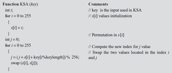
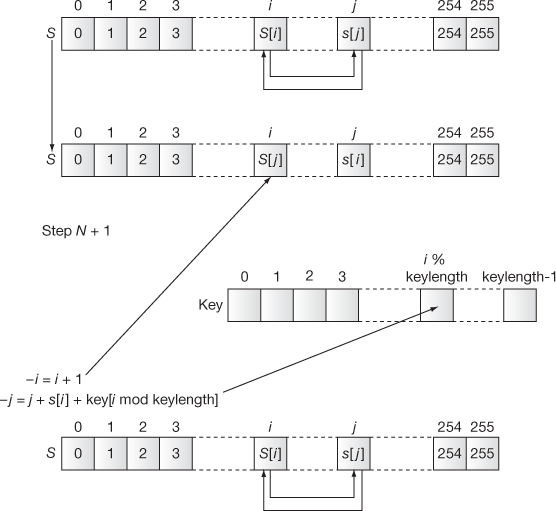
Figure 5.6 Permutation process
5.5.3 The Pseudo Random Generation Algorithm
In this algorithm, the actual key stream is generated which could be used for performing encryption operation in the sender side. Algorithm 5.2 explains about the PRGA.
Figure 5.7 shows the key stream selection process used in the PRGA.
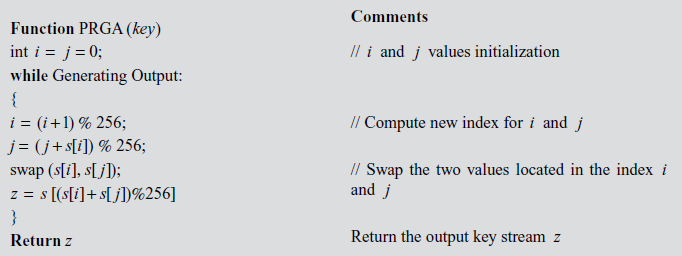
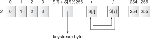
Figure 5.7 Key stream selection process
5.5.4 Encryption and Decryption
Once the keystream has been generated successfully, the encryption of the plaintext can be performed by XORing the key stream and plaintext. Figure 5.8 shows the RC4 encryption operation performed using an XOR operation. Figure 5.9 shows the RC4 decryption operation performed using an XOR operation. The basic steps that are performed in the RC4 encryption are given below:
- Choose a secret key.
- Run the KSA to generate the initial permuted array.
- Run the PRGA to generate a key stream.
- Now the amount of key stream generated is equal to the amount of bytes for doing encryption operation.
- XOR with key stream with the plaintext data to generate the encrypted stream.
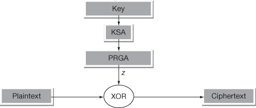
Figure 5.8 RC4 encryption operation
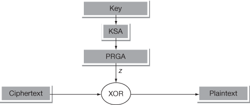
Figure 5.9 RC4 decryption operation
The basic steps that are performed in the RC4 decryption are given below:
- Use the same key that was used in the encryption operation.
- Generate a key stream by running the KSA and PRGA algorithms.
- XOR is the key stream with the ciphertext to generate the plaintext.
Example 5.2:
Generate a key stream using RC4 for a simple 4-byte example where  = {0, 1, 2, 3},
  = {1, 3, 5, 7} and
  .
.
Solution:
KSA Algorithm
First iteration ( = 0,
= 0,  = 0,
= 0,  = {0, 1, 2, 3}):
 =
=  = (0 + 0 + 1) = 1
Swap  with
with  :
:  = {1, 0, 2, 3}
Second iteration ( = 1,
= 1,  = 1,
= 1,  = {1, 0, 2, 3}):
 =
=  = (1 + 0 + 3) = 0 (mod 4)
Swap  with
with  :
:  = {0, 1, 2, 3}
Third iteration ( = 2,
= 2,  = 0,
= 0,  = {0, 1, 2, 3}):
 = (0 + 2 + 5) = 7 mod 4 = 3
Swap  with
with  :
:  = {0, 1, 3, 2}
Fourth iteration ( = 3,
= 3,  = 3,
= 3,  = {0, 1, 3, 2}):
 = (3 + 2 + 7) = 0 (mod 4)
Swap  with
with  :
:  = {2, 1, 3, 0}
PRGA Algorithm
Reset  , Recall
  = {2, 1, 3, 0}
 + 1 = 1
 = 0 + 1 = 1
Swap  and
and  :
:  = {2, 1, 3, 0}
Output  =
=  = [2] = 3
5.6 RC5
RC5 was designed by Ronald Rivest in the year 1994. In RC5, RC stands for ‘Rivest Cipher’. RC5 is a fast symmetric block cipher that uses the same key for performing encryption and decryption operations [7]. RC5 is a fast symmetric block cipher because it uses computationally efficient operations which can be found in typical microprocessors. Therefore, RC5 is suitable for hardware and software implementations. RC5 cipher takes less memory and hence it may be easily implemented on smart cards or other devices that has a small amount of storage space. RC5 is easy to implement. In addition to this, RC5 focuses on data-dependent rotations in which one word of intermediate results is cyclically rotated by an amount decided by the low-order bits of another intermediate result. The major strength of RC5 cipher relies on this data-dependent rotation. Finally, RC5 uses a variable length cryptographic key and hence it provides high security.
5.6.1 Principles of RC5
RC5 is a word-oriented cipher in which a  -bit word is given as input and a
  -bit word is produced as output. RC5 is a block cipher where two-word input is given as plaintext block and two word ciphertext is produced as output block. The word should be greater than zero (
 ). But, the actual choice for
  is 32 bits. Therefore, 64 bits is given as a plaintext block (because two words = 2 × 32 = 64 bits) and 64 bits is produced as ciphertext block. The number of rounds
  used in the RC5 is larger than DES and hence it provides a high level of security. The RC5 uses an expanded key table
  which is derived from the secret key. The size
  of table
  also depends on the number of rounds
  . The table size
  can be computed by
  , which means that the table can store 34 words if
  value is 16. In addition to this, the RC5 has a variable length secret key
  specified by parameter
  , where
  defines the number of bytes in the secret key K. Here, b can take the values from 1 to 255. Based on these parameters, there are various types of RC5 algorithms. For example, RC5-32/16/10 has 32-bit words, 16 rounds, 10 byte secret key (80 bits) and an expanded key table that consists of 34 words (
 = 2 × 17 = 34).
Suppose, if the key size is changed in the above example and if it is RC5-32/16/17, then this will work like DES. Because, the input size, number of rounds and key size are same. Hence, the main purpose of replacing the DES algorithm by RC5 is that the input size, number of rounds and key size are dynamic which can be changed depending on the applications. For example, some applications may need high speed. For those applications, small r value can be selected. In some other applications such as key management, security is a major concern and speed is unimportant. In such kind of key management applications, r value can be increased. Hence, r = 32 might be a good choice for key management application. Similarly, key size and word size can also be increased in key management applications.
RC5 cipher consists of three phases, namely key expansion, RC5 encryption and RC5 decryption algorithm. The key expansion phase is mainly used to expand the users secret key K and fill the expanded key array S. RC5 encryption algorithm encrypts the message using the expanded key array S and RC5 decryption algorithm decrypts the ciphertext using the array S.
5.6.2 RC5 Key Expansion
The key expansion phase uses two magic constants to expand the users secret key K. It consists of three steps that are given below:
- Converting the secret key
- Initializing the array

- Mixing the secret key
These three steps are executed based on the magic constants defined for RC5. The two magic constants are defined using the following equations for a random word  .
.
 = Odd
= Odd 
 )
)
 = Odd
= Odd 
 )
)
where e = 2.718281828459… (base of natural logarithms) and  = 1.618033988749… (golden ratio). In the above equations, odd(x) gives the odd integer nearest to x. For example, if w = 16, then
  = b7e1 and
  = 9e37. Similarly, for various sizes of word
  , different
  and
and  values can be computed.
Converting the Secret Key
The first step in the key expansion phase is to copy the secret key  to
to  into another array
  to
to . In this array
  , the value
  represents the maximum number of words which can be computed by
  , where
 is the number of bytes/words
  . If anything is unfilled, then that byte positions are filled as zero in the array
  . If
. If  , then the value of
  is filled with 1 and
  = 0. Algorithm 5.3 summarizes this process.
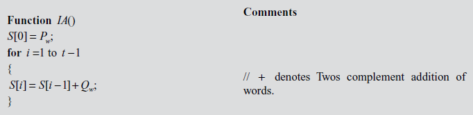
Initializing the Array S
The second step in the key expansion process is to initialize the array  to a fixed pseudo random bit pattern using an arithmetic progression. This arithmetic progression is determined by two magic constants
  and
and  . This arithmetic progression will have a period up to
  , since
  is an odd integer. Algorithm 5.4 is used to implement array initialization.
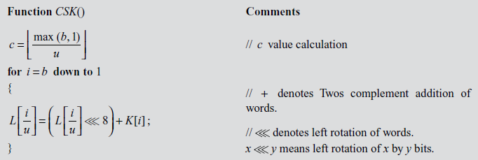
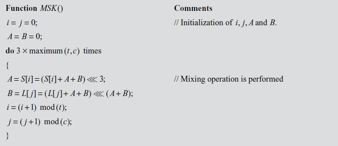
Mixing the Secret Key
The third step in the key expansion phase is to mix the user’s secret key using the three steps defined in Algorithm 5.5 above the arrays S and L. This process is clearly explained in Algorithm 5.5.
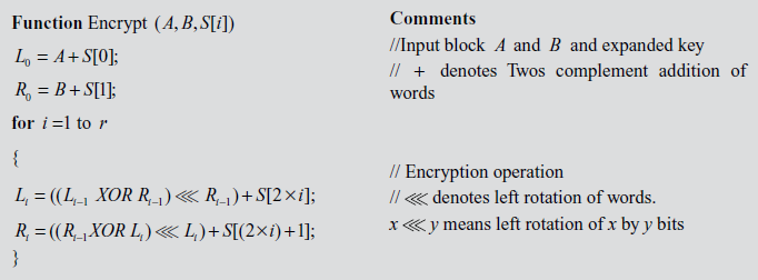
5.6.3 RC5 Encryption
RC5 encryption algorithm accepts two  bit registers
  and
and  as input plaintext block and the expanded key array
  to
to  . Using the input block A and B and the expanded key array, RC5 encryption algorithm performs the encryption operation. Algorithm 5.6 explains about RC5 encryption algorithm.
5.6.4 RC5 Decryption
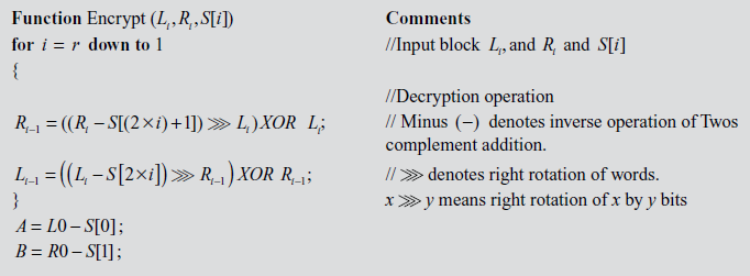
RC5 decryption algorithm uses two w-bit registers Li, and Ri as input ciphertext block and the expanded key array  . Using the input block Li, and Ri and the expanded key array, RC5 decryption algorithm performs the decryption operation. Algorithm 5.7 explains about RC5 decryption algorithm.
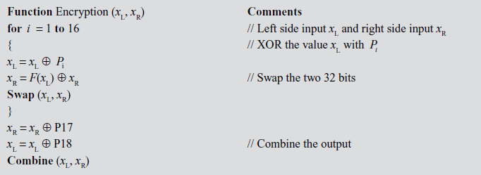
5.7 International Data Encryption Algorithm
International data encryption algorithm, often abbreviated as IDEA, is a secure block encryption algorithm which was designed successfully by Xuejia Lai and James L. Massey [8] of ETH-Zurich for the first time in the year 1991. The success of this algorithm is attributed to the use of simple algebraic structures. The original algorithm as described by the authors had few modifications and finally it was called IDEA. This algorithm permits the effective protection of the transmitted data from unauthorized access by the intruders probably. The main difference between DES and IDEA is that IDEA uses different keys for encryption and decryption operation. However, the keys are related in a complex manner.
5.7.1 Principles of IDEA
The algorithm works on 64-bit plaintext and ciphertext block. During the encryption, the 64-bit plaintext is divided into four sub-blocks with each sub-block size of 16 bits. The four sub-blocks are represented as P1, P2, P3 and P4, each of which consists of 16 bits. Each of the sub-block iterates through 8 rounds and a single output transformation phase. The eight rounds perform arithmetic and logical operations for necessary transformations. Moreover, the same sequences of arithmetic operations are repeated inside each sub-block. The initial step in the encryption process is to divide the 64-bit plaintext into four equally sized blocks and it will be given for round 1 input processing. The output of round 1 shall serve as the input of round 2. Similarly, the output of round 2 serves as the input of round 3, and so on. Finally, the output of round 8 is the input for the output transformation, in which the output is the result of 64-bit ciphertext. The basic structure of IDEA is shown in Figure 5.10. In this figure, each round is further divided into two parts, namely, IDEA odd round process and IDEA even round process. Therefore, the entire 8 rounds of operations are represented as 16 rounds (2 × 8 = 16) plus one output transformation round. Since IDEA is a symmetric key algorithm, the algorithm uses the same key for encryption and decryption operations. The size of the key used in this algorithm is 128 bits. During the entire encryption operation, a total of 52 keys (round 1 to round 8 and output transformation phase) are used which is actually generated from a 128-bit key. In each round (round 1 to round 8), six subkeys are used wherein each subkey consists of 16 bits. However, the output transformation uses only 4 subkeys which are comparatively lesser than the input phase.
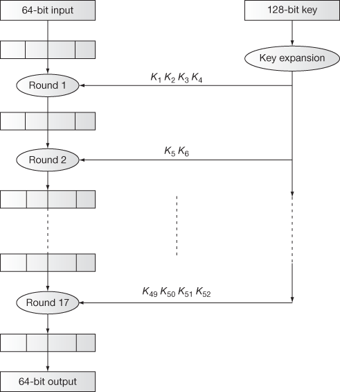
Figure 5.10 Basic Structure of IDEA
IDEA primitive operations
The basic operations in the input and output phase needed in the entire process are given in this section. Operations needed in the first 8 rounds are given as follows:
- Multiplication modulo

- Addition modulo

- Bitwise XOR.
The operations needed in the output transformation phase are given as follows:
- Multiplication module

- Addition modulo
 .
.
All the above-mentioned operations are performed on 16-bit sub-blocks. For simplicity, the multiplication modulo  is represented by ⊗ symbol, the addition modulo
  is represented by + symbol and bitwise XOR will be represented by the traditional symbol
  .
.
5.7.2 Key Expansion
Now, let us examine the key expansion for the encryption process. During the key expansion, first 8 subkeys are generated from the 128-bit key value. For generating the remaining subkeys to be used in different rounds, a simple circular left shift operation is performed in the original key with respect to 25 bits. For example, subkey K1 uses the first 16 bits of the original key, subkey K2 uses the next 16 bits, and so on till subkey K8. Hence, first eight subkeys (K1 to K8) are taken from the original key value and its size is 128 bits (16 × 8). This process is shown in Figure 5.11.
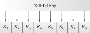
Figure 5.11 Generation of subkeys (K1 to K8)
For generating the remaining subkeys, start from the 25th bit, wrap up around the first 25 bits at the end, and take the 16-bit chunks. This process is repeated up to generating K52. This process is shown in Figure 5.12.

Figure 5.12 Generation of remaining subkeys
5.7.3 IDEA Encryption and Decryption
IDEA encryption consists of two types of process, namely IDEA odd round process and IDEA even round process. The IDEA odd round process accepts four data blocks (P1, P2, P3 and P4) and four subkeys (K1, K2, K3 and K4) as input and produces four data blocks (P1, P2, P3 and P4) as partial output which will be used as the input to the next round. These four values are produced by performing multiplication modulo  and addition modulo
  operations. Figure 5.13 shows the way of processing the input in the IDEA odd round process. Figure 5.14 shows the way of processing the input in IDEA even round process. The IDEA even round process accepts four data blocks (P1, P2, P3 and P4) and two subkeys (K5, K6) as input. Among the four data blocks, the first two data blocks (P1, P2) are XOR-ed together and the output is stored in Q1. Similarly, the next two data blocks (P3, P4) are XOR-ed together and the output is stored in Q2. These two values (Q1, Q2) and the two subkeys (K5, K6) are given as input to Mangler function. The Mangler function produces two outputs (Q3, Q4) from (Q1, Q2) and (K5, K6). The output produced by the Mangler function is defined as follows:
Q3 = ((K5 ⊗ Q1) + Q2) ⊗ K6
Q4 = (K5 ⊗ Q1) + Q3
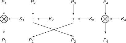
Figure 5.13 IDEA odd round process
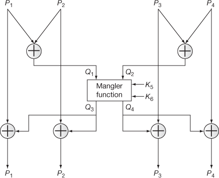
Figure 5.14 IDEA even round process
The decryption operation is the same as the encryption process except that the subkeys are derived using a different algorithm. The main strength of IDEA algorithm is that IDEA uses a key whose size is two times greater than the key used in the DES. Thus,  trials are needed to find the key using brute-force attack.
5.8 Blowfish Encryption
Blowfish was designed in the year 1993 by Bruce Schneier [9]. This technique was initiated to find an alternative for the existing algorithms like DES, AES and triple-DES by increasing the speed of encryption and decryption operations. The speed of the Blowfish cipher is increased by performing simple addition and XOR operations. The Blowfish is a fast and efficient symmetric block cipher, because it encrypts the plaintext data on large 32-bit microprocessors at a rate of 26 clock cycles per byte. The Blowfish cipher takes less memory, because it takes less than 5 K of memory for running encryption and decryption algorithms.
5.8.1 Principles of Blowfish
The Blowfish is a Feistel network block cipher that encrypts a 64-bit block of plaintext using a variable length key size of 448 bits. Since, the key length is of variable length, it can be in the range of 32 to 448 bits. But, the default key size is 28 bits. The Blowfish cipher is very much suitable for the applications where keys are not changed frequently like password management and web applications. The Blowfish cipher consists of three phases, namely key expansion, Blowfish encryption phase and Blowfish decryption phase. During the key expansion phase, the user’s secret key is expanded into several subkey arrays to produce 4168 bytes. The Blowfish encryption algorithm encrypts the message using the subkeys and the Blowfish decryption algorithm decrypts the ciphertext using the same subkeys.
5.8.2 Key Expansion
During the key expansion phase, the original key is broken into a set of subkeys, and thereby two arrays are used. They are P-array and S-box array. The P-array consists of 18 subkeys, where each subkey size is 32 bits. The S-box array contains 256 entries. In the S-box array, each S-box accepts 8 bits as input and produces 32 bits as output. In each round, one entry of the P-array is used. Subsequent to the final round, an XOR operation is performed with each half of the data block. To generate the subkeys, initialize the P-array and S-boxes with a fixed string. After the string initialization, first 32 bits of the P-array values are XORed with the key bits. For example, XOR the first 32 bits of key with P1 and XOR the second 32 bits of key with P2. This output is denoted as P1 and P2. After that, encrypt the new P1 and P2 with the modified subkeys and output is denoted as P3 and P4. Repeat this process for 521 times in order to calculate the new subkeys for the P-array and the four S-boxes. If large number of subkeys need to be generated in the Blowfish cipher, these subkeys are computed before starting the encryption and decryption operations.
5.8.3 Encryption and Decryption
During the data encryption, a simple function is iterated for 16 times where each round performs a key-dependent permutation and a data-dependent substitution. All addition operations are performed as an XOR operation on 32-bit words. The Blowfish encryption splits the given input into two 32-bit halves. Each 32-bit input is further divided into four 8 bits, and uses them as input to the S-boxes. The outputs are XOR-ed and added using arithmetic modulo  to produce the final 32-bit output. The basic structure of Blowfish encryption operation is shown in Figure 5.15. The basic structure of Blowfish function F is shown in Figure 5.16. Algorithm 5.8 explains about the Blowfish encryption algorithm. Blowfish decryption operation is exactly same as that of encryption operation except that P1, P2 … P18 are used in the reverse order.
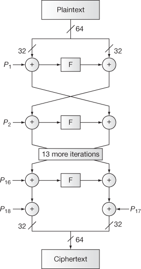
Figure 5.15 Blowfish encryption
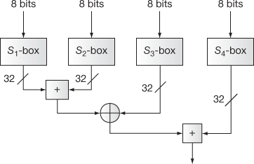
Figure 5.16 F function of Blowfish
The Blowfish function can be written as given as follows:

5.9 CAST-128
CAST-128 is a symmetric block cipher algorithm that was developed by carlisle adams and stafford tavares (CAST) in the year 1996 [10]. This algorithm is based on the CAST design procedure. The algorithm works on Feistel Network structure which has similar encryption and decryption operations and such network construction follows an iterative procedure. The input plaintext is 64-bit block in size and the key size varies from 40 to 128 bits depending on the target application. This algorithm uses 12 rounds for key sizes up to 80 bits (i.e. 40, 48, 56, 64, 72 and 80 bits) and uses full 16 rounds for key sizes greater than 80 bits. Padding is necessary for the key sizes that are less than 128 bits. It uses eight substitution boxes (S-boxes) each with 256 entries in which S1 to S4 boxes are used for encryption and decryption process and S5 to S8 boxes are used for key scheduling.
5.9.1 CAST-128 Algorithm
In CAST-128, the overall operation is similar to the data encryption standard (DES). The full encryption algorithm is described in Figure 5.17 and explained in the following four steps.
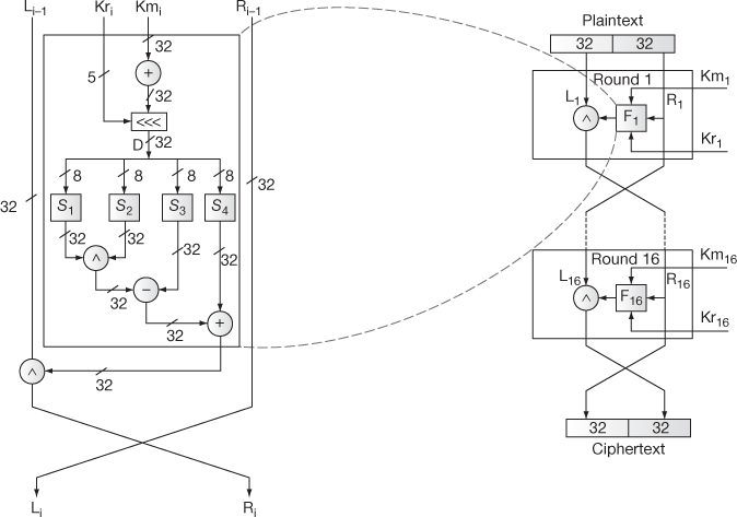
Figure 5.17 CAST-128 encryption algorithm
In order to discuss the encryption algorithm of CAST-128, consider a 64-bit plaintext m1 … m64 and a 128-bit key K = k1 … k128. To encrypt the 64-bit plaintext using 128-bit key, four steps are used. The four steps are key schedule, processing the plaintext, structure of round function and swapping. All the four steps are explained as follows:
1. Key schedule
It is the process used to compute 16 pairs of subkeys { ,
,  } from the 128-bit key. Each subkey size is 32 bits. In this process, totally 32 keys are computed. Among the 32 keys, 16
  key values and 16
  key values are available. The first 16 keys (
 –
– ) are used for ‘masking’ and are called masking keys. This set is denoted as Km (m for ‘masking’). The remaining 16 keys (
 –
– ) are used for ‘rotation’ and are called rotation keys. In the rotation subkeys, the least significant 5 bits are used for the left circular shift operations and the remaining bits are useless bits. This set is denoted as Kr (r for ‘rotation’).
CAST-128 has eight substitution boxes (S-boxes) [S1 – S8] in which the S-boxes S1, S2, S3, and S4 are called round function S-boxes. These four S-boxes are used for encryption and decryption. The remaining four S-boxes (S5, S6, S7, and S8) are used for key schedule S-boxes to generate the subkeys. Each S-box is represented as a 256
  32 array matrix. Each S-box receives 8 bits as input and produces 32 bits as output. The 8-bit input is used to choose a particular row from the S-Box and the 32-bit value available in that row is produced as an output [11]. For instance, consider 128-bit key:
 a0a1a2a3a4a5a6a7a8a9aAaBaCaDaEaF, where a0 and aF stands for the least significant byte and the most significant byte, respectively. Let us assume that t0 … tF be the intermediate (temporary) bytes. Let Si[] represents ith S-box and let ‘^’ represents XOR operation. From the given 128-bit key, the subkeys are formed as follows:
t0t1t2t3 = a0a1a2a3 ^ S5[aD] ^ S6[aF] ^ S7[aC] ^ S8[aE] ^ S7[a8]
t4t5t6t7 = a8a9aAaB ^ S5[t0] ^ S6[t2] ^ S7[t1] ^ S8[t3] ^ S8[aA]
t8t9tAtB = aCaDaEaF ^ S5[t7] ^ S6[t6] ^ S7[t5] ^ S8[t4] ^ S5[a9]
tCtDtEtF = a4a5a6a7 ^ S5[tA] ^ S6[t9] ^ S7[tB] ^ S8[t8] ^ S6[aB]
 = S5[t8] ^ S6[t9] ^ S7[t7] ^ S8[t6] ^ S5[t2]
 = S5[tA] ^ S6[tB] ^ S7[t5] ^ S8[t4] ^ S6[t6]
 = S5[tC] ^ S6[tD] ^ S7[t3] ^ S8[t2] ^ S7[t9]
 = S5[tE] ^ S6[tF] ^ S7[t1] ^ S8[t0] ^ S8[tC]
a0a1a2a3 = t8t9tAtB ^ S5[t5] ^ S6[t7] ^ S7[t4] ^ S8[t6] ^ S7[t0]
a4a5a6a7 = t0t1t2t3 ^ S5[a0] ^ S6[a2] ^ S7[a1] ^ S8[a3] ^ S8[t2]
a8a9aAaB = t4t5t6t7 ^ S5[a7] ^ S6[a6] ^ S7[a5] ^ S8[a4] ^ S5[t1]
aCaDaEaF = tCtDtEtF ^ S5[aA] ^ S6[a9] ^ S7[aB] ^ S8[a8] ^ S6[t3]
 = S5[a3] ^ S6[a2] ^ S7[aC] ^ S8[aD] ^ S5[a8]
 = S5[a1] ^ S6[a0] ^ S7[aE] ^ S8[aF] ^ S6[aD]
 = S5[a7] ^ S6[a6] ^ S7[a8] ^ S8[a9] ^ S7[a3]
 = S5[a5] ^ S6[a4] ^ S7[aA] ^ S8[aB] ^ S8[a7]
t0t1t2t3 = a0a1a2a3 ^ S5[aD] ^ S6[aF] ^ S7[aC] ^ S8[aE] ^ S7[a8]
t4t5t6t7 = a8a9aAaB ^ S5[t0] ^ S6[t2] ^ S7[t1] ^ S8[t3] ^ S8[aA]
t8t9tAtB = aCaDaEaF ^ S5[t7] ^ S6[t6] ^ S7[t5] ^ S8[t4] ^ S5[a9]
tCtDtEtF = a4a5a6a7 ^ S5[tA] ^ S6[t9] ^ S7[tB] ^ S8[t8] ^ S6[aB]
 = S5[t3] ^ S6[t2] ^ S7[tC] ^ S8[tD] ^ S5[t9]
 = S5[t1] ^ S6[t0] ^ S7[tE] ^ S8[tF] ^ S6[tC]
 = S5[t7] ^ S6[t6] ^ S7[t8] ^ S8[t9] ^ S7[t2]
 = S5[t5] ^ S6[t4] ^ S7[tA] ^ S8[tB] ^ S8[t6]
a0a1a2a3 = t8t9tAtB ^ S5[t5] ^ S6[t7] ^ S7[t4] ^ S8[t6] ^ S7[t0]
a4a5a6a7 = t0t1t2t3 ^ S5[a0] ^ S6[a2] ^ S7[a1] ^ S8[a3] ^ S8[t2]
a8a9aAaB = t4t5t6t7 ^ S5[a7] ^ S6[a6] ^ S7[a5] ^ S8[a4] ^ S5[t1]
aCaDaEaF = tCtDtEtF ^ S5[aA] ^ S6[a9] ^ S7[aB] ^ S8[a8] ^ S6[t3]
 = S5[a8] ^ S6[a9] ^ S7[a7] ^ S8[a6] ^ S5[a3]
 = S5[aA] ^ S6[aB] ^ S7[a5] ^ S8[a4] ^ S6[a7]
 = S5[aC] ^ S6[aD] ^ S7[a3] ^ S8[a2] ^ S7[a8]
 = S5[aE] ^ S6[aF] ^ S7[a1] ^ S8[a0] ^ S8[aD]
The remaining –
– half is computed in the same way similar to the procedure explained above for the same 128-bit key ‘a0a1a2a3a4a5a6a7a8a9aAaBaCaDaEaF’.
2. After generating the necessary subkeys, the plaintext is split into two 32-bit halves L1 = m1 … m32 and R1 = m33 … m64.
3. There are 16 rounds in the encryption algorithm that ranges from 1 to 16. Decryption also uses the same number of rounds, but the keys are used in reverse order. In each round, Li and Ri values are calculated as given as follows:
Li = R(i–1)
Ri = L(i–1) ^ f(R(i–1),  ,
,  ), where f is defined as a round function.
There are three types of round functions that are defined for CAST-128. They are represented as Function Type 1, Function Type 2 and Function Type 3. These three types of round functions are used for different rounds, which are identified by the value of i. For example, Function type 1 is used for six rounds (i = 1, i = 4, i = 7, i = 10, i = 13, and i = 16). Here, i denotes the round number. Function type 1 is shown in Figure 5.18. Function type 1 is defined as follows:

Figure 5.18 Function type 1
Function Type 1: D = (( + Data<<<
 ))
))
f = ((S1[D1] ^ S2[D2]) − S3[D3]) + S4[D4])
where,
Data is the input data,
D1 to D4 are the most significant bytes from the least significant byte of D, respectively,
S1, S2, S3, S4 are S-Box 1, 2, 3 and 4, respectively,
‘ ’ and ‘
 ’ are modulo addition and subtraction, respectively,
‘ ’ is bitwise exclusive OR,
‘ ’ is a circular left shift operation.
Function type 2 is shown in Figure 5.19. Function type 2 is used for the rounds 2, 5, 8, 11 and 14. The operations performed in Function type 2 are summarized as follows:

Figure 5.19 Function type 2
Function Type 2: I = (( ^ Data <<<
 ))
))
f = ((S1[D1] − S2[D2]) + S3[D3]) ^S4[D4])
Function type 3 is shown in Figure 5.20. Function type 3 is used for rounds 3, 6, 9, 12, and 15. The operations performed in Function type 3 are summarized as follows:
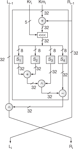
Figure 5.20 Function type 3
Function Type 3: I = (( − Data <<<
  ))
))
f = ((S1[D1] + S2[D2]) ^S3[D3]) − S4[D4])
4. The final blocks L16, R16 are exchanged to get the ciphertext.
5.9.2 Strength of CAST
CAST-128 is a Feistel cipher that has 12 to 16 rounds of operation based on the key size. The rotation keys are used to give intrinsic immunity to this algorithm to protect from linear and differential attacks. This algorithm also uses a mixture of four primitive operations, namely modulo addition, modulo subtraction, bitwise exclusive-OR and left circular shift operations in the round functions. The main purpose of using the XOR operation in this algorithm is that it has the property of self-invertible. Hence, separate XOR operations are not used for encryption and decryption operations. At last, the eight S-boxes used in the round function have a minimum non-linearity to provide confusion. This algorithm has a cryptographic strength in proportion to its key size and also has very fine encryption or decryption routine.
5.10 RC2
In cryptography, RC2 (Ron’s Code or Rivest Cipher) is a block cipher algorithm designed by Ron Rivest in the year 1987. At first, this algorithm is not accepted by the national security agency (NSA), and then the NSA proposed a couple of changes in RC2, which Rivest included. After additional negotiations, this algorithm was approved in 1989. In RC2, the length of the given plaintext and the ciphertext is 64 bits and the key length varies from 8 to 1024 bits (1 to 128 bytes). The property of effective key size is the important feature of RC2 in terms of flexibility offered to the user. There are two distinct sections to be used in RC2. First process is the key expansion process and the second process is the encryption and decryption process.
5.10.1 Key Expansion Process
In the case of the key expansion process, two operations are applied that are byte operations and 16-bit word operations. For both operations, an array of  is used to store the sixty-four 16-bit round keys. Then a 64-bit plaintext is encrypted using the array
  . For 16-bit word operations, the locations of the buffer will be denoted as
  , where each
  is a 16-bit word. For byte operations, the array of locations of the buffer will be denoted as
  , where each
  is an eight-bit byte. In this case,
  .
.
Suppose a user selects  bytes of key such that
  Hence, the key expansion procedure locates the
  byte key in the buffer locations from
  However, based on the value of
  , the algorithm chooses a maximum effective key length in bits, denoted by U1. Based on the effective key length U1 in bits, the key expansion algorithm then derives the effective key length in bytes U8 and a mask UM using the following equations.
 and
and

For example, let us consider the key size  bits, hence the effective key length is U1
  = 128. Therefore,
 and
and


= 
=  =
=
=  (binary format)
= 
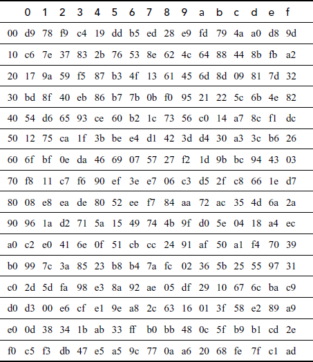
Both the key expansion process and the encryption process rely on the usage of a substitution table called PITABLE (P[0], … , P[255]) was deduced from the expansion of π = 3.14159…. It is an array having the random permutation values range from 0, to 255. Table 5.2 shows the PITABLE in hexadecimal notation [12]:
Table 5.2 PITABLE
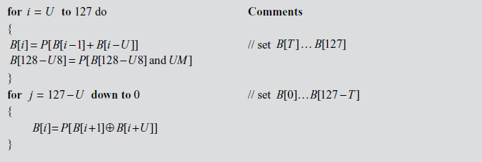
Key Expansion Algorithm
Algorithm 5.9 summarizes this process [12].
5.10.2 Encryption Algorithm
In the encryption process, there are rounds are used. One is named as a MIXING round and the other is named as a MASHING round. In the encryption process, 18 rounds of mixing and mashing operations are performed. The following primitive operations are used in the encryption algorithm.
- Sixteen-bit word addition which is performed modulo 232: +
- Bitwise exclusive-OR:

- Bitwise complementation: ~
- Bitwise logical AND: &
- Left circular rotation: x
 y
y
An input array of four 16-bit words W[0], W[1], W[2], W[3] is used to store the initial plaintext.
Mixing Round
The mix operation is defined as follows. A mixing round consists of Mix  Mix
Mix  Mix
Mix  and Mix


where s[0] =1, s[1] = 2, s[2] = 3 and s[3] = 5.
Example:


Mashing Round
The primitive ‘Mash  operation is defined as follows. A mixing round consists of Mix W[0], Mix W[1], Mix W[2], Mix W[3].

Example:


The whole encryption operation is explained as follows.
- Initialize words
 to have the 64-bit plaintext value.
 - Expand the key so that words
 become defined.
 - Initialize the value of j to zero.
- Execute five mixing rounds

- Execute one mashing round.
- Execute six mixing rounds

- Execute one mashing round.
- Execute five mixing rounds

Note that in RC2, each mixing round uses four key words [1], in such a way that each key word is used exactly once in the mixing round.
5.10.3 Decryption Operation
The decryption operation also uses the same primitive operations that are used in the encryption operation. The decryption process is the reverse of encryption process. The ‘mix’ and ‘mash’ operations of the encryption algorithm are reversed and are named as ‘r-mixing’ and ‘r-mashing’, respectively.
r-mixing round
The r-mix function is defined as follows:

j = j – 1
r-mashing round
The r-mash function is defined as follows:

The whole decryption operation is explained as follows.
- Initialize words
 to have the 64-bit ciphertext value.
 - Expand the key so that words
 become defined.
 - Initialize the value of j to 63.
- Execute five mixing rounds

- Execute one mashing round.
- Execute six mixing rounds

- Execute one mashing round.
- Execute five mixing rounds

Take down that each mixing round uses four key words, so that each key word is practised precisely once in a mixing round. RC2 is most vulnerable to a related-key attack by using 234 chosen plaintexts. In cryptography, a related-key attack is a kind of cryptanalysis in which the attacker can monitor the function of a cipher by using numerous different keys whose values are initially unknown, but however some mathematical relationships connecting these different keys are known to the attacker.
Key Terms
8 Subkeys
Addition modulo
Algebraic structures
Array initialization
Bitwise Xor
Blowfish
Blowfish decryption
Blowfish encryption
Blum Blum Shub Generator
Brute-force attack
Data-dependent rotations
Decryption
DES
Deterministic random bit generator (DRBG)
Double DES
Encryption
Even round process
Fast symmetric block cipher
Feistel network
Function type
IDEA
Inverse DES
Key expansion
Key expansion process
Key schedule
Key scheduling algorithm (KSA)
Left shift operation
Linear Congruential Generators
Magic constants
Mangler function
Masking keys
Meet-in-the-middle attack
Multiplication modulo
Odd round process
P-Array
PITABLE
Plaintext, ciphertext pair
Practically known attacks
PRNG’s seed
Pseudo random bit pattern
Pseudo random function (PRF)
Pseudo random generation algorithm (PRGA)
Pseudo random number generator (PRNG)
Random word
RC4
RC5
Related-key attack
Rotation keys
Round functions
S-array
S-Box array
Single output transformation
Subkeys
Triple DES
Variable length key
W-Bit registers
Word-oriented cipher
XOR Operation
Summary
- In double DES, two symmetric keys were used for encryption and decryption.
- During encryption, double DES takes 64-bit plaintext and 112-bit key as inputs to produce 64-bit ciphertext as output.
- During decryption, DES encryption operation is performed in inverse by taking 64-bit ciphertext and 112-bit key as input to produce 64-bit plaintext as output.
- Meet-in-the-middle attack can be applied to double DES.
- During encryption, the triple DES takes 64-bit plaintext and 112/168-bit key as inputs to produce 64-bit ciphertext as output.
- During decryption, inverse DES operation is performed by taking 64-bit ciphertext and 112/168-bit key as input to produce 64-bit plaintext as output.
- A pseudo random number generator (PRNG) is a function which is used to generate sequence random numbers using mathematical equation.
- A PRNG is also known as a deterministic random bit generator (DRBG).
- Three types of PRNGs are linear feedback shift registers, linear congruential generators and Blum Blum Shub generator.
- The Vernam one-time pad uses TRNG whereas RC-4 uses PRNG.
- The difference between the PRNG and TRNG is that the PRNG generates a random number as output that many eventually repeat.
- RC4 is a stream cipher which was invented by Ron Rivest in the year 1987.
- RC4 is used by important protocols such as SSL, TSL, WPA and WEP, etc.
- RC4 algorithm generates a pseudo random number which will be used as a key to encrypt the plaintext and to generate the corresponding ciphertext.
- In RC4, the pseudo random number is generated from a variable length key after performing the two algorithms, namely KSA and PRGA.
- Among the two algorithms, the KSA is used to generate the permutation array. The PRGA is used to generate a pseudo random number which will be used as a key stream.
- Once the keystream has been generated successfully, the encryption of the plaintext can be performed by XORing the key stream and plaintext.
- In RC4 decryption, use the same key that was used in the encryption operation.
- RC5 is a fast symmetric block cipher that uses the same key for performing encryption and decryption operations.
- RC5 is a word-oriented cipher in which a w-bit word is given as input and a w bit is produced as output.
- RC5 is suitable for hardware and software implementations and it takes less memory to implement on smart cards.
- RC5 uses a variable length cryptographic key and hence it provides high security.
- RC5 cipher consists of three phases, namely key expansion, RC5 encryption and RC5 decryption.
- The key expansion phase is mainly used to expand the users secret key K and fill the expanded key array S.
- The key expansion phase uses two magic constants to expand the users secret key K.
- RC5 encryption algorithm encrypts the message using the expanded key array S and RC5 decryption algorithm decrypts the ciphertext using the array S.
- RC5 encryption algorithm accepts two w-bit registers A and B as input plaintext block and the expanded key array
 to
to  .
. - RC5 decryption algorithm uses two w-bit registers
 and Ri as input ciphertext block and the expanded key array
  .
. - IDEA permits the effective protection of the transmitted data from unauthorized access by the intruders probably.
- The main difference between DES and IDEA is that IDEA uses different keys for encryption and decryption operation.
- During the encryption, the 64-bit plaintext is divided into four sub-blocks with each sub-block size is 16 bits.
- In IDEA, each of the sub-block iterates through 8 rounds and a single output transformation phase. The eight rounds perform arithmetic and logical operations for necessary transformations.
- Operations needed in the first 8 rounds are multiplication modulo, addition modulo and bitwise XOR.
- IDEA encryption consists of two types of process, namely IDEA odd round process and IDEA even round process.
- Mangler function produces two outputs.
- In the decryption of IDEA, the subkeys are derived using a different algorithm. Remaining operations are same similar to encryption.
- Main strength of IDEA algorithm is that IDEA uses a key whose size is two times greater than the key used in the DES.
- In IDEA,
 trials are needed to find the key using brute-force attack.
 - Blowfish was initiated to find an alternative for the existing algorithms like DES, AES and triple-DES by increasing the speed of encryption and decryption operations.
- The Blowfish is a fast and efficient symmetric block cipher, because it encrypts the plaintext data on large 32-bit microprocessors at a rate of 26 clock cycles per byte.
- The Blowfish cipher takes less memory, because it takes less than 5 K of memory for running encryption and decryption algorithms.
- Blowfish is a Feistel network block cipher that encrypts a 64-bit block of plaintext using a variable length key size of 448 bits.
- Blowfish cipher is very much suitable for the applications where keys are not changed frequently like password management and web applications.
- Blowfish cipher consists of three phases, namely key expansion, Blowfish encryption phase and Blowfish decryption phase.
- During the key expansion phase, the original key is broken into a set of subkeys and thereby two arrays are used.
- During the data encryption, a simple function is iterated for 16 times where each round performs a key-dependent permutation and a data-dependent substitution.
- Blowfish decryption operation is exactly same as that of encryption operation except that P1, P2, …, P18 are used in the reverse order.
- The Feistel network structure has similar encryption and decryption operations and such network construction follows an iterative procedure.
- The key schedule is the process used to compute 16 pairs of subkeys {
 ,
,  } from the 128-bit key. Each subkey size is 32-bits. In this process, totally 32 keys are computed. Among the 32 keys, 16
  key values and 16
  key values are available.
 - In key schedule, the first 16 keys (
 –
– ) are used for ‘masking’ and are called masking keys. This set is denoted as Km (m for ‘masking’). The remaining 16 keys (
 –
– ) are used for ‘rotation’ and are called rotation keys. In the rotation subkeys, the least significant 5 bits are used for the left circular shift operations and the remaining bits are useless bits. This set is denoted as Kr (r for ‘rotation’).
 - There are three types of round functions that are defined for CAST-128. They are represented as Function Type 1, Function Type 2 and Function Type 3. These three types of round functions are used for different rounds, which are identified by the value of i.
- Key expansion process and the encryption process rely on the usage of a substitution table called PITABLE (P[0], … , P[255]) was deduced from the expansion of π = 3.14159…. It is an array, having the random permutation values range from 0 to 255.
- In the case of the key expansion process, both byte operations and 16-bit word operations are applied. For both operations, an array of
 is used to store the sixty-four 16-bit round keys. Then a 64-bit plaintext is encrypted using the array
  .
. - In cryptography, a related-key attack is a kind of cryptanalysis in which the attacker can monitor the function of a cipher by using numerous different keys whose values are initially unknown, but however some mathematical relationships connecting these different keys are known to the attacker.
Review Questions
- Explain about double DES encryption and decryption algorithm.
- Explain about triple DES encryption and decryption algorithm.
- What is meet-in-the-middle attack? Explain it with a suitable example.
- Differentiate DES and double DES.
- What is PRNG?
- Write short notes on linear congruential generator.
- Write Blum Blum Shub (BSS) generator algorithm. Give an example.
- Explain about RC4 key scheduling, encryption and decryption algorithms in detail.
- Generate a key stream using RC4 for a simple 4-byte example, where 8 = {0, 1, 2, 3},
 = {11, 13, 15, 17} and
  .
. - Given short notes on RC5 key expansion process.
- Explain about RC5 encryption and decryption operation in detail.
- What are the advantages of RC5?
- What is IDEA? Explain in detail about IDEA encryption and decryption operations.
- Explain in detail about Blowfish encryption and decryption operations.
- Give a brief explanation about CAST-128 encryption algorithm.
- What are the different function types used in CAST-128 and give a brief explanation with suitable diagrams?
- Explain the key scheduling process in CAST-128.
- Give brief notes about the strength of CAST-128.
- Draw and explain the pictorial representation of the CAST-128 encryption algorithm.
- What is the use of masking and rotation keys in the CAST-128 algorithm?
- Define PITABLE.
- Explain the key expansion process of RC2 in detail.
- Explain the encryption and decryption operations in a detailed manner.
- List out the steps involved in both encryption and decryption operations.
- What is related-key attack?
References
- homes.cerias.purdue.edu/~crisn/courses/cs555/cs555_lect5.pdf
- cacr.uwaterloo.ca/hac/about/chap15.pdf
- http://www.vocal.com/wp-content/uploads/2012/05/tdes.pdf
- http://www.random.org/randomness/
- http://www.win.tue.nl/~berry/papers/ima05bbs.pdf
- http://www.cs.rit.edu/~ark/winter2011/482/team/u4/report.pdf
- http://people.csail.mit.edu/rivest/Rivest-rc5rev.pdf
- ftp://180.211.120.110/04%20IT%20Department/RNK/SE/International%20Data%20Encryption%20Algorithm.pdf
- http://www.cs.rit.edu/~ark/spring2012/482/team/u2/report.pdf
- http://people.chu.edu.tw/~chlee/Crypto/Crypto4_1p.pdf
- https://tools.ietf.org/html/rfc2144
- https://www.ietf.org/rfc/rfc2268.txt
- http://people.csail.mit.edu/rivest/pubs/KRRR98.pdf