Table of Contents for
Cryptography and Network Security
 Cryptography and Network Security
Published by
Pearson Education India, 2016
Cryptography and Network Security
Published by
Pearson Education India, 2016
- Cover
- Title Page
- Engineering Chemistry
- Contents
- Foreword - 1
- Foreword - 2
- Preface
- Acknowledgements
- CHAPTER 1 Cryptography
- CHAPTER 2 Mathematics of Modern Cryptography
- CHAPTER 3 Classical Encryption Techniques
- CHAPTER 4 Data Encryption Standard
- Chapter 5 Secure Block Cipher and Stream Cipher Technique
- Chapter 6 Advanced Encryption Standard (AES)187
- Chapter 7 Public Key Cryptosystem
- Chapter 8 Key Management and Key Distribution
- Chapter 9 Elliptic Curve Cryptography
- Chapter 10 Authentication Techniques
- Chapter 11 Digital Signature
- Chapter 12 Authentication Applications
- Chapter 13 Application Layer Security
- Chapter 14 Transport Layer Security
- Chapter 15 IP Security
- Chapter 16 System Security
- Appendix: Frequently Asked University Questions with Solutions
- Basic Mechanical Engineering
Chapter 4
Data Encryption Standard
4.1 Simplified Data Encryption Standard
Simplified-data encryption standard (S-DES) was developed by Edward Schaefer as a teaching tool to understand data encryption standard (DES). S-DES is much similar to DES [1,2] in terms of operations performed and operators used in the encryption and decryption process. Moreover, S-DES uses simple operations and hence this algorithm is not used for real-time applications when compared to DES algorithm. In general, S-DES algorithm uses two basic operations for encryption as well as for decryption: substitution and permutation. In substitution technique, each element of the plaintext is substituted by another element. In permutation technique, the plaintext elements are rearranged/permuted in some order. The S-DES supports two rounds of encryption and decryption processes. Figure 4.1 shows the overall architecture of S-DES algorithm.
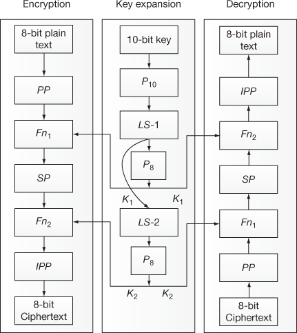
Figure 4.1 Overall architecture of S-DES
The overall architecture of S-DES algorithm consists of three processes. The left-hand side process shows encryption process, the middle one shows the key expansion process and the right-hand side shows decryption process. In encryption process, the S-DES algorithm takes an 8-bit block of plaintext and encrypts it using a 10-bit key to produce an 8-bit block of ciphertext as output. In the key expansion process, two sub-keys are produced for two different rounds of operation from a 10-bit key value. In the decryption process, an 8-bit block of ciphertext and the same 10-bit key are used to produce the original 8-bit block of plaintext.
4.1.1 S-DES Encryption
The encryption process of S-DES works in five phases as shown below:
- Primary permutation (PP);
- Primary function (Fn1);
- Secondary permutation (SP)– swapping;
- Secondary function (Fn2); and
- Inverse primary permutation (IPP).
Primary Permutation
In PP, an 8-bit block of plaintext is taken as an input and then the input bits are permuted using a PP function. At the end of this operation, all 8-bit of the plaintext are preserved by rearranging them in some order. In general, PP can be expressed as shown in Equation (4.1). Figure 4.2 gives an example for P10 table.
P = PP (Plaintext)(4.1)
where P is the permuted output.
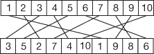
Figure 4.2 P10 Table
Primary Function
This is the first round function and is one of the important functions used in S-DES algorithm. Figure 4.4 shows the details of primary and secondary functions. The operations performed in the Fn1 are explained as follows:
- In the beginning, right-hand side (R1) of the permuted plaintext (4 bits) is given as an input to expansion and permutation (EP1) function, thereby 4 bits are expanded to 8 bits. The EP1 operation can be expressed as shown in Equation (4.2). Figure 4.3 gives an example for EP1.
EO = EP1(R1)(4.2)
where
EO – Expanded output
R1 – Right-hand side 4-bits
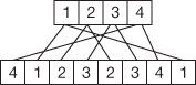
Figure 4.3 Expansion and permutation (EP1)
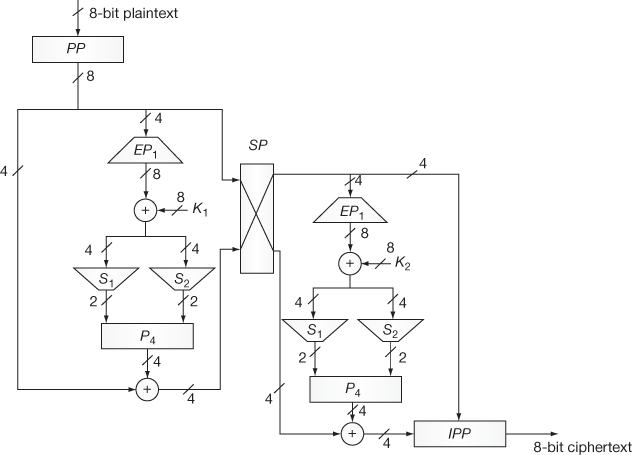
Figure 4.4 Detail structure of S-DES encryption
- In the second stage of this function, an XOR operation is performed between EO value and the first sub-key K1 as shown in Equation (4.3).
 (4.3)
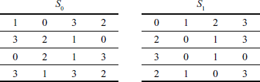
(4.3) - After that, 8 bits obtained in this way are separated into two 4-bits and these separated bits are given as input to two S-boxes S1 and S2 respectively. S1 box will produce 2 bits and S2 box will produce 2 bits as outputs. Table 4.1 shows the two S-boxes used in the S-DES algorithm.
Table 4.1 S-boxes used in the S-DES
- The outputs of S1 box (OS1) and S2 box (OS2) are concatenated and are given as input to permutation table (P4) as shown in Equation (4.4).
 (4.4)
(4.4) - Finally, an XOR operation is performed between PO value and left hand side (L1) of the permuted plaintext (4 bits) value to produce SW1 as output. This operation is shown in Equation (4.5).
 (4.5)
(4.5) - Finally the output of Fn1 is shown in Equation (4.6).
Fn1 = L1 ⊕ (P4 (S-Box (K1 ⊕EP1 (R1))))(4.6)
Secondary Permutation – Swapping
In the SP, 4-bit value of SW1 and right hand side 4-bit value of the permuted plaintext (R1) are swapped with each other to produce the swap output (SWO) of 8 bits as shown in Equation (4.7).
 (4.7)
(4.7)
Secondary Function
This is the second round function and is also an important function used in S-DES algorithm. The operations performed in this function are very similar to first round function. One of the differences between this function and the first round function is that a new sub-key K2 is passed as an input to this function. Remaining stages are same as shown in Figure 4.4. The entire process of the second round function can be written as shown in Equation (4.8).
 (4.8)
(4.8)
Inverse Primary Permutation
In the IPP phase, 4 bits of Fn2 output and 4 bits of the right hand side input (R2) are concatenated and it is taken as an input to IPP. These input bits (8 bits) are permuted using the inverse (reverse) of PP function to produce the ciphertext. At the end of this operation all 8 bits are preserved by rearranging them in some order. In general, the IPP can be expressed as shown in Equation (4.9).
Ciphertext (CT) = IPP (Fn2 || R2)(4.9)
The overall process of encryption can be summarized as shown in Equation (4.10).
Ciphertext = IPP(Fn2 (SP(Fn1 (PP(Plaintext)))))(4.10)
4.1.2 Key Expansion Process
In S-DES algorithm, a 10-bit key is securely communicated between the sender and the receiver for encrypting and decrypting the messages. The encryption/decryption key expansion phase generates two 8-bit sub-keys from the 10-bit key value that are used in Fn1 and Fn2. Figure 4.5 shows the key expansion process. The process of encryption key generation is shown below:
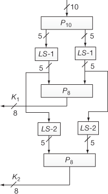
Figure 4.5 Key expansion process of S-DES
- At first, the 10-bit input key is permuted to some order which is expressed as P10.
- After the permutation process, the 10-bit key separates into two 5-bit keys for which 1-bit left circular shift operations (LS1) are performed individually.
- In this stage, the result of individual left circular shift (1-bit) operations is concatenated and it is given as input to permutation table (P8) which eliminates first two bits and permutes the remaining bits. Figure 4.6 shows the P8 table used for key expansion process.
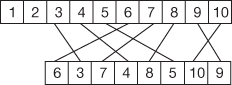
Figure 4.6 P8 used for key expansion
- Therefore, the 8 bits obtained as output from permutation table (P8) is called primary sub-key (K1). In general, primary key expansion can be expressed as shown in Equation (4.11).
 (4.11)
 - In addition to this, the key expansion phase also generates another 8-bit key. For generating this key, the output of LS1 is taken as the input and it is given to 2 bits left circular shift operations (LS2) where left shift operations are performed individually for each 5 bits.
- The result of individual left circular shift (2-bits) operations are concatenated and it is given as the input to permutation table (P8), which eliminates first two bits and permutes the remaining bits.
- Finally, the 8-bit obtained as output from the permutation table (P8) is called secondary sub-key (K2). In general, secondary sub-key generation can be expressed as shown in Equation (4.12).
 (4.12)
4.1.3 S-DES Decryption
The third process shown in Figure 4.1 is decryption process. The decryption process of the S-DES also works through all the five phases used for the encryption process. However, in the decryption process, an 8-bit ciphertext is given as input to produce an 8-bit plaintext using the same 10-bit key value. One of the important differences between S-DES encryption and S-DES decryption is that the keys are used in reverse order. Therefore, the secondary key (K2) is given as a sub-key for the first round operation and primary key (K1) is given as a sub-key for the second round. The overall process of decryption can be summarized as shown in Equation (4.13).
Plaintext = IPP(Fn2(SP(Fn1(PP(Ciphertext)))))(4.13)
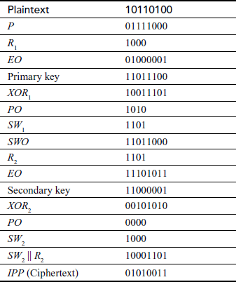
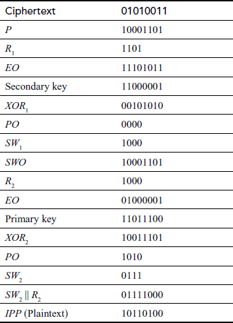
Example 4.1:
Encrypt and decrypt the plaintext B4 (10110100) using S-DES for the key value 2CC (1011001100).
Solution
Encryption process:
Key generation process:
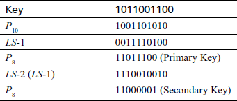
Decryption process:
4.2 Data Encryption Standard
In the year 1974, IBM designers submitted an algorithm to the national bureau of standards (NBS). Afterwards it was renamed by national institute of standards and technology (NIST) internally under the name LUCIFER to protect data during transmission and storage. The NBS evaluated this algorithm with the assistant of the national security agency (NSA). Based on the evaluation, they changed the LUCIFER algorithm and built a new algorithm as the DES on July 15, 1977 [3].
4.2.1 DES Encryption and Decryption
The DES is a symmetric block cipher that makes use of only one key for both encryption and decryption operations. The term ‘symmetric’ is used since the same key is used for both encryption and decryption operations. The DES is a block cipher that encrypts a 64-bit block of plaintext using a 56-bit key to produce a 64-bit block of ciphertext. The key is presented as a 64-bit block from which an effective 56-bit key is generated for encryption and decryption operations. In the 64-bit key value, every bits are parity bits used for parity checking which are discarded and contain no effect on DES’s security. Figure 4.7 shows the DES encryption algorithm that consists of three processes. The right-hand side process shows the key expansion process and middle one shows the way in which plaintext is processed. Finally, the left-hand side process shows the structure of a single round operation. The plaintext processing starts with a 64-bit plaintext that consists of four stages that are given below:
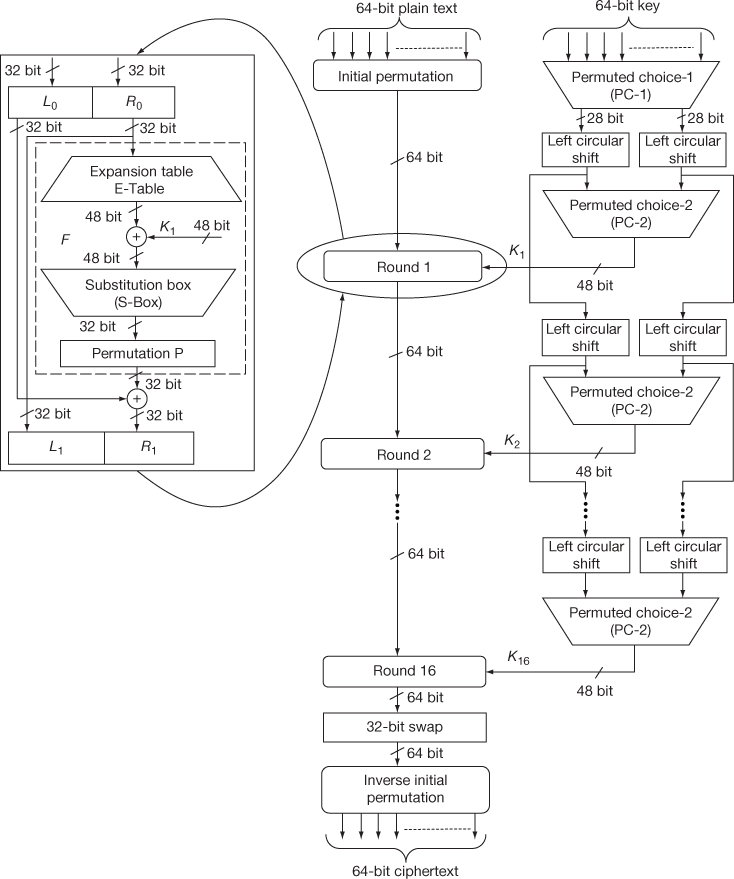
Figure 4.7 The DES algorithm for encryption operation
- Initial permutation (IP)
- 16 rounds of operation
- 32-bit swap
- Inverse initial permutation
These four stages are applied to the plaintext for converting (tranforming) the plaintext into ciphertext. These four stages are also used in the DES decryption operation in which the keys are in reverse order. The first stage IP is used to rearrange the plaintext bits into some confused format. The second stage consists of 16 rounds of operation in which simple substitution and permutation operations are performed. The third stage is a 32-bit swap where the left-hand and right-hand side 32 bits are swapped. Finally, inverse initial permutation is used to perform the permutation operation which is the inverse of IP.
In the key generation process, a 64-bit key is given as the input to permuted choice-1 that removes any 8 bits from the given key value. This result is passed to permuted choice-2 through left circular shift from which a sub-key Ki is generated for each round. Totally, 16 sub-keys are generated for 16 rounds of operations.
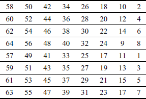
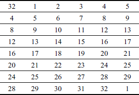
Initial Permutation
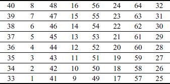
At first, an IP is performed on the entire 64-bit block of plaintext data based on the IP table shown in Table 4.2. During the IP, the bits are rearranged to form the ‘permuted input’. The permuted table output is then split into two 32 bits sub-blocks, L0 and R0, which are then given as the input to first round among 16 rounds. In general, the input of each round is represented as Li–1 and Ri–1 where the subscript i denotes the current round of operation.
Table 4.2 Initial permutation (IP)
16-Rounds of Operation
Each round is identical to all the 16 rounds and it mainly performs substitution and transposition operations. To perform this, each round accepts an input which is represented as two 32-bit value Li–1 and Ri–1. Using these two 32-bit values, each round performs four transformations as given below:
- Expansion
- • XOR operation with the corresponding round sub-key
- Substitution
- Permutation
Initially, the right-hand side 32 bits (R0) of the permuted 64 bits is expanded into 48 bits using the expansion table (E-table). The E-table is shown in Table 4.3.
Table 4.3 Expansion table (E-table)
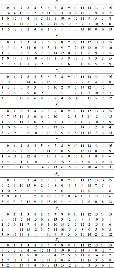
The expanded 48 bits are XOR-ed with a 48-bit sub-key value generated by the key generation process. The output produced by the XOR operation is given as input to S-box [4] as shown in Figure 4.8. The S-box consists of eight S-boxes and each S-box is represented as a 4 × 16 array matrix. Each S-box receives 6 bits as input and produces 4 bits as output. The outer two bits of the 6-bit chunk are used to indicate the row index (0 to 3) of the S-box array and the inner four bits of the 6-bit chunk are used to indicate the column index (0 to 15) of the S-box array. For example, if an input to S2 (second S-Box) is ‘111011’, and then the input has outer bits ‘11’ and inner bits ‘1101’. In this input, the outer bits are used to locate the third row, and inner bits are used to select 13th column. The corresponding output produced by S2 would be ‘0101’ (95). So, the output of S-box is a 4-bit chunk pointed by the row and column indices [5]. Table 4.4 shows the values of the all S-boxes.
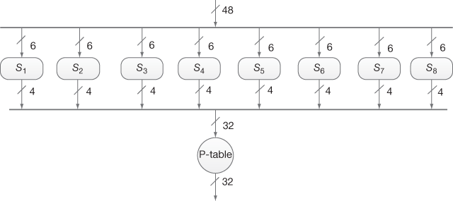
Figure 4.8 S-box substitutions
Table 4.4 S-boxes
Eight S-boxes produce a total of 32 bits which are given as the input to permutation table P to perform permutation operation to avoid a number of potential attacks [6]. Table 4.5 shows the P table. Therefore, in each round Fi (i = 1, 2, …, 16), Li and Ri values are computed. In general, this can be represented as shown below:
Li = Ri – 1
Ri = Li– 1 ⊕ F(Ri – 1, Ki)
where F is the round function and Ki is the sub-key.
Table 4.5 Permutation (P)
32-bit Swapping
At the end of the 16th round, the 32-bit Li and Ri output values are swapped to create the 64-bit pre-output.
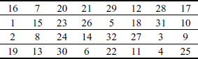
Inverse Initial Permutation
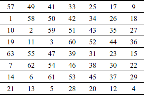
Finally, the pre-output is given as the input to inverse initial permutation IP−1 as defined in Table 4.6, which is the inverse of the IP. The output of IP−1 table is the 64-bit ciphertext.
Table 4.6 Inverse initial permutation (IP−1)
4.2.2 DES Key Expansion
In the key expansion process, the 64-bit key is first given as the input to the permuted choice-1 (PC-1) table which is used to remove eight bits from the given key and generates a 56-bit key. Table 4.7 shows the PC-1 table.
Table 4.7 Permuted choice-1 (PC-1)
The 56-bit key is subdivided into two blocks of 28-bit keys. Every 28-bit block is given as the input to two left circular shift boxes which performs left circular shift operation according to the schedule of left circular shift defined in Table 4.8 for each round. The left circular shift operation is performed to produce a new key for each round. Because, a small change in the plaintext or the key should affect many bits in the ciphertext. This effect is called Avalanche effect.
Table 4.8 Schedule of left shift

After performing left circular shift operation, the two 28-bit blocks are given as the input to the permuted choice-2 (PC-2) table to generate a 48-bit round sub-key for each round represented as Ki (different for each round), where ‘i’ in Ki denotes the current round of operation. Table 4.9 shows the PC-2 table which is used to remove eight bits from the 56-bit key to generate the 48-bit key after performing left circular shift operation. This 48-bit key value is used to perform XOR with the corresponding right-hand side input Ri.
Table 4.9 Permuted choice one (PC-2)
4.2.3 DES Decryption
In DES decryption, all the four stages that are used in the encryption operation are used. The main difference between the DES encryption and the DES decryption is that the sub-keys are supplied in reverse order. For example, the sub-key K16 is used as a key value to Round 1 to perform decryption, K15 is used in Round 2 and so on.
Example 4.2:
Encrypt the plaintext ‘0123456789ABCDFA’ for the key value ‘0123456789ABCDFA’ using the DES algorithm. During the encryption operation, toggle a single-bit position in the plaintext according to a given student roll number. Consider, for example, the roll number is seven and hence toggle the seventh bit of the plaintext and calculate the ciphertext for a single round of operation.
Solution
Let us consider the given plaintext 0123456789ABCDFA. This plaintext contains 16 hexadecimal digits and 64 bits in the binary form. Therefore, the plaintext can be written as 0000000100100011010001010110011110001001101010111100110111111010 in binary.
Let us consider the given roll number as seven. Hence, toggle the seventh bit position of the plaintext from 0 to 1. The new plaintext (M) can be written as
M= 0000001100100011010001010110011110001001101010111100110111111010. At first, an IP is performed on the entire 64-bit block of plaintext data based on the IP table shown in Table 4.2. After IP, plaintext (M1) can be written as
M1= 1100110010000000010011000111111111110000101010101111000010101011.
The permuted table output is then split into two 32-bit sub-blocks, L0 and R0 which are then given as the input to first round among 16 rounds.
L0= 11001100100000000100110001111111.
R0= 11110000101010101111000010101011.
The right-hand side 32 bits (R0) is expanded into 48 bits (E) using the E-table as shown in Table 4.3.
E= 111110100001010101010101111101000001010101010111.
Let the given key = 0123456789ABCDFA. This key is also in a hexadecimal form, so the 64-bit binary form of the key (K) can be written as
K = 0000000100100011010001010110011110001001101010111100110111111010.
This 64-bit key is first given as the input to the permuted choice-1 (PC-1) table shown in Table 4.7, which is used to remove eight bits from the given key and generates a 56-bit key. Hence, the 56-bit key (K1) is
K1= 11110000110011001010101010001010101001001100111100000000.
The resulting 56-bit key is then treated as two 28-bit quantities which are labelled as C0 and D0. These values are sent to left circular shift operation with respect to 1 or 2 bits governed by Table 4.8.
C0= 1111000011001100101010101000.
D0= 1010101001001100111100000000.
After performing 1-bit left circular shift on two 28-bit quantities, the output is labelled as C1 and D1.
C1= 1110000110011001010101010001.
D1= 0101010010011001111000000001.
Therefore,
C1D1= 11100001100110010101010100010101010010011001111000000001.
After performing left circular shift operation, the two 28-bit blocks are given as the input to PC-2 table as shown in Table 4.9 to generate a 48-bit round key (K2).
K2= 000110110000001001100111100110110100100110100001.
This 48-bit key value is used to perform XOR operation with the corresponding right-hand side input E.
X=E ⊕ K2 = 111000010001010100110010011011110101110011110110.
The output produced by the XOR operation is given as input to S-box as shown in Figure 4.8. The S-box consists of eight S-boxes. Each S-box receives 6 bits as input and produces 4 bits as output. Table 4.4 shows the values of the all S-boxes. The output of XOR is divided into eight 6-bit quantities and is served as inputs to each S-box. The 32-bit output (S) from eight S-boxes can be written as
S= 00111100110000011001000101011101.
The 32-bit output from eight S-boxes is given as the input to permutation table P as shown in Table 4.5 to perform permutation operation to avoid a number of potential attacks. The permuted output (PER)can be written as
PER= 10101011000110010010101100110010.
After computing PER, calculate the input to round 2 as shown below:
R1 = L0 ⊕ PER
L0 =R0
Hence,
 =
=  = 01100111100110010110011101001101
Therefore, the 64-bit output is denoted as  .
.
 = 1111000010101010111100001010101101100111100110010110011101001101
Hence, the output or ciphertext in hexadecimal form after round 1 can be written as

4.3 Strength of DES
This section discusses about the security strength of the DES algorithm by considering the various attacks that can be performed on it.
4.3.1 Brute-force Attack
DES has a weakness due to its shorter key length of 56 bits and thereby brute-force attack is easily performed. In order to do that, an intruder has to connect many power machines in parallel and he/she has to perform a distributive exhaustive key search to find the key value. Using this key search, the intruder can find 50 million keys per second and hence the key can be found within 5 to 10 days. Nevertheless, by increasing the key lengths of DES to 112 bits in double DES and triple DES, brute-force attack has turned into more unfeasible. Thus, brute-force attack has become the most challenging task on double DES and triple DES. Apart from brute-force attack, the DES is vulnerable to two more attacks, namely differential cryptanalysis and linear cryptanalysis. In this part, we offer a short summary of the two attacks such as differential cryptanalysis and linear cryptanalysis.
4.3.2 Differential Cryptanalysis
Differential cryptanalysis is a kind of cryptanalysis which is mainly applied to block ciphers. In addition to that, this cryptanalysis is also applicable to cryptographic hash functions and stream ciphers. Eli Biham and Adi Shamir have demonstrated differential cryptanalysis against a number of hash functions and encryption algorithm, including the DES around 1990s. Eli Biham and Shamir noted that differential cryptanalysis is very complex and difficult for DES but little alterations to the algorithm would produce it much more vulnerable [7]. The DES can be effectively broken using differential cryptanalysis in 247 trials by choosing 247 chosen plaintexts. Differential cryptanalysis is the first attack that can break DES in less than 257 trials. Differential cryptanalysis is concentrated a huge role in the design of the permutation P and the S-boxes.
Differential Cryptanalysis Attack
The main idea behind differential cryptanalysis attack is to evaluate the differences in the ciphertext for properly selecting the pair of plaintext and hence obtain the information about the key. Hence, this attack is also known as chosen plaintext attack. Here, the XOR function is used to find the difference between two blocks of bits since sub-key Ki of each round is XORed with Ri – 1 after passing Ri – 1 through E-table. The differential cryptanalysis uses XOR operation to remove some randomness introduced by the key. The differential cryptanalysis is possible when the chosen plaintext pairs are very large.
Let us consider a pair of plaintexts P and P1. The XOR between these two values denotes a specific value P1, i.e. P′ = P ⊕ P1. The plaintexts P and P1 are subdivided into two halves PLi, PRi and P1Li, P1Ri, respectively. To illustrate differential cryptanalysis, we have considered only three rounds of operation up to PL4 and PR4 ciphertext. Initially, the DES encryption algorithm starts with the plaintext PL1 and PR1. The DES encryption function is applied to PL1, PR1 and P1L1, P1R1 to generate PL4, PR4 and P1L4, P1R4 as shown in Figure 4.9. From the figure, it is clear to understand the following things:
 and
and 


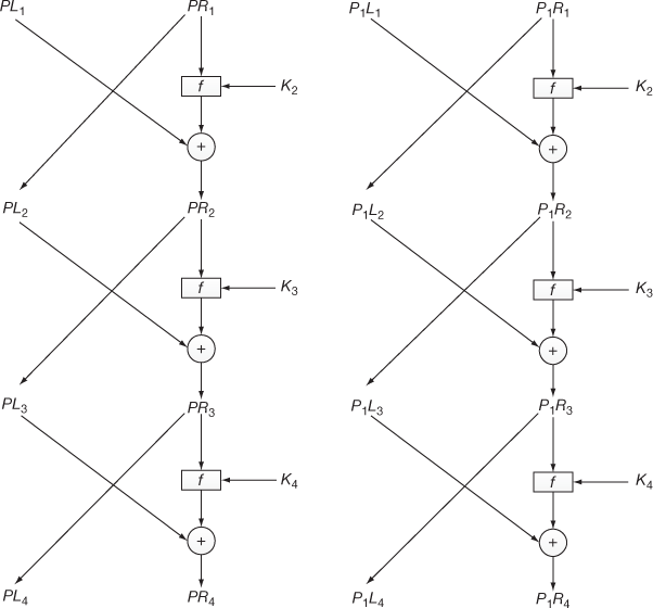
Figure 4.9 Three rounds of operation
Let us assume that

 and
and
Therefore,
 and
and

This can be rewritten as

Since  ,
,

To calculate the key value, expand E(PL4) and E(P1L4) using the expansion table as shown below.
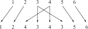
The S-box has four inputs where the first bit is used to represent the rows and the last three bits are used to represent the columns. The output of the S-box has three bits. For instance, let us consider an input 1100 where the first bit 1 represents the second row of the S-box and the last three bits 100 represent the fourth column of the S-box.
The first and last three bits of E(L′4) are given as the input to two S-boxes, respectively. Here, E(L′4 ) is considered as the input of the S-boxes and the first and last three bits of PR′4 ⊕ PL′1 represents the output of the S1 and S2 boxes, respectively. List out the pairs that generate the output (K4) of S1 and S2 boxes. S1 produces the left K4 bits and S2 produces the right K4 bits. Then calculate the pair E(PL4) ⊕ K4, E(P1L4) ⊕ K4. Finally, work out all the possibilities of K4 until finding one possibility of K4.
Example 4.3:
The following is an exercise for differential cryptanalysis.
Solution
Let us consider the plaintext and the corresponding ciphertext after round 4. The plaintext is subdivided into two parts PL1 and PR1.
 9000111011011
 9000011100101
Consider another one message with 
 101110011011
 = 100100011000
Using the expansion table, find
 = 00000011
 = 10101000


 101001
 111101
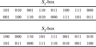
Then, find the S-boxes output 
= 111101 ⊕ 101001 = 010100
Hence, the output of S1 box is 010 and from S2 box is 100. S1 generates the output 010 for the pairs (1001, 0011), (0011, 1001). The first four bits of K4 can be calculated by E(PL4) ⊕ K4 90000 ⊕ K4. Therefore, the first four bits of K4 are in (1001, 0011). The output of S2 box is 100. S2 generates the output 100 for the pairs (1100, 0111), (0111, 1100). The last four bits of K4 can be calculated by E(PL4) ⊕ K4 = 0011 ⊕ K4. Therefore, the last four bits of K4 are in (1111, 0100).
Similarly, repeat the steps for another plaintext.
 9010111011011
 101110011011
Similar analysis can be performed to find that the first four bits of K4 are in (1000, 0011) and the last four bits of K4 are in (1011, 0100). By combining the previous and current information, it is concluded that the first four bits of K4 are 0011 and the last four bits of K4 are 0100. Hence, K9= 00*001101 because K4 starts with fourth bit of K. To find the third bit of K,9first use 0 and encrypt the plaintext PL1 || PR1. If it did not produce the correct ciphertext, then the key will be 001001101 or else the key is 000001101.
4.3.3 Linear Cryptanalysis
In cryptography, there are two most widely used attacks on block ciphers: one is differential cryptanalysis and the other is linear cryptanalysis. Linear cryptanalysis was invented by Mitsuru Matsui [8], which is a common form of cryptanalytic attack based on finding linear approximations to the action of a block cipher. In this attack, the key bits can be guessed by means of some collected plaintexts and corresponding ciphertexts. For example, some of the plaintext bits are XORed together and some of the ciphertext bits are XORed. In this case, the XOR value of plaintext bits and ciphertext bits, produces the single bit, which is equal to the XOR of some key bits.

This is a linear equation which holds for some probability p. In an ideal cipher p = 1/2 if p ≠ 1/2, then this bias can be utilized. This cryptanalytic attack for constructing linear approximations is mainly concentrated in the S-boxes. In DES, S-boxes have six input bits and four output bits. There are 63 (26 – 1) useful ways through which the input bits can be combined together using XOR and there are 16 (24 – 1) useful ways through which the output bits can be combined together using XOR. For each S-box, the probability is evaluated for a randomly chosen input. Moreover, an input XOR combination equals some output XOR combination, if there is a linear relation with high enough bias between an inputs XOR combination and outputs XOR combination, and then linear approximations can be constructed. Linear approximations for the S-boxes must be combined together with the other operations such as key mixing and permutation in order to find the linear equations. From the linear equations, for each set of values of the key bits, count the number of times the approximation holds true over all the known plaintext–ciphertext pairs. It is accepted because the correct partial key will make the approximation to hold with a high bias.
4.4 Modes of operation
In DES algorithm, the key size is only 64 bits and hence it can encrypt only 64-bit plaintext at a time. To encrypt a plaintext message larger than 64 bits, it is necessary to divide the given message into 64-bit block of data. Each 64-bit message can be encrypted using the same 64-bit key value using DES encryption operation. If bit size of the last block is smaller than the capacity of the current block size, then the last block of the bits must be padded so that all the bits are equal to the actual block size. To provide the facility of encrypting large amount of data using the DES algorithm in various applications, NIST developed five modes of operation for the DES algorithm in the year 1981. In these five modes of operation, a single block/stream operation is repeatedly applied to securely transform a large amount of data (e.g. 1024 bits) sent from Alice to Bob. Based on that, these five modes of operation are classified into block ciphers and stream ciphers. In block cipher modes of operation, the input message is divided into n-number of blocks each consists of 64-bit data. All the n-number of blocks are encrypted using the same key value. In contrast to block cipher modes of operation, only one byte or bit is encrypted using the same key value in stream cipher modes of operation. In stream cipher modes of operation, padding is not required since they efficiently use the stream size. The modes of operation are categorized into five types as follows:
- Electronic code book (ECB) mode
- Cipher block chaining (CBC) mode
- Cipher feedback (CFB) mode
- Output feedback (OFB) mode
- Counter (CTR) mode.
Among these five types, ECB and CBC modes are used for block ciphers. CFB and OFB modes are used for stream ciphers. CTR mode is used for both block ciphers and stream ciphers.
4.4.1 Electronic Code Book Mode
In this method, the plaintext is divided into n blocks based on the size of the plaintext. The n blocks are represented into a set P as shown in Equation (4.14). Each block of the plaintext is independently encrypted with a common key (K) to produce different ciphertext for each plaintext as shown in Equation (4.15). Similarly, each block of the ciphertext can independently be decrypted with a common key (K) to produce original plaintext for each ciphertext value as shown in Equation (4.16).
 (4.14)
 (4.15)
 (4.16)
In this section, we use E to represent encryption operation and D to represent the decryption operation. Figure 4.10 shows the encryption and decryption operations performed in ECB mode. Here, independent encryption of plaintext and independent decryption of ciphertext are performed.
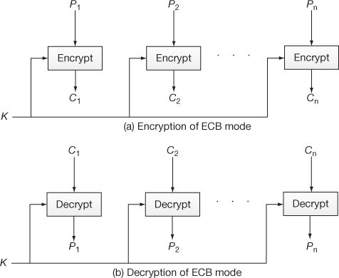
Figure 4.10 Encryption and decryption process of ECB mode
Algorithm 4.1 gives the procedure to perform encryption operation in ECB mode.
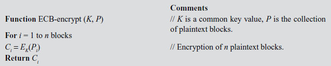
The advantages and disadvantages of ECB are listed as follows:
Advantages
- ECB is simple in implementation.
- Bit errors occurred by noisy channels only affect the respective block and they do not affect the other blocks.
- In ECB mode, all blocks can be operated in parallel.
Disadvantages
- In ECB mode, two identical plaintext blocks occur at some distance will produce the same ciphertext value thereby known plaintext attack is possible.
- Security services are being compromised by the intruder using the known plaintext attack.
Application
The ECB mode is used for communicating small messages from sender to receiver. For example, it can be used for communicating the DES key value from Alice side to Bob side.
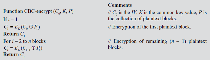
4.4.2 Cipher Block Chaining Mode
In this method, the plaintext is divided based on ECB method as shown in Equation (4.14). In the beginning, an initialization vector (IV) denoted as C0 and first plaintext (P1) are XORed and then the resultant value is encrypted using a common key (K) to produce the first ciphertext (C1) as shown in Equation (4.17).
 (4.17)
For the next time, first ciphertext (C1) and second plaintext (P2) are XORed and then the resultant value is encrypted using a common key (K) to produce the second ciphertext (C2)9 In general, the encryption operation excluding the first block can be expressed as shown in Equation (4.18).
 (4.18)
In the decryption operation of CBC mode, first (Ci) is decrypted in following ways as shown below:


Finally, the result of the decryption process is shown in Equation (4.19).
 (4.19)
Figure 4.11 shows the encryption and decryption process performed in CBC mode. From the figure, it is very clear to understand that output of one block is supplied as one of the inputs to next block.
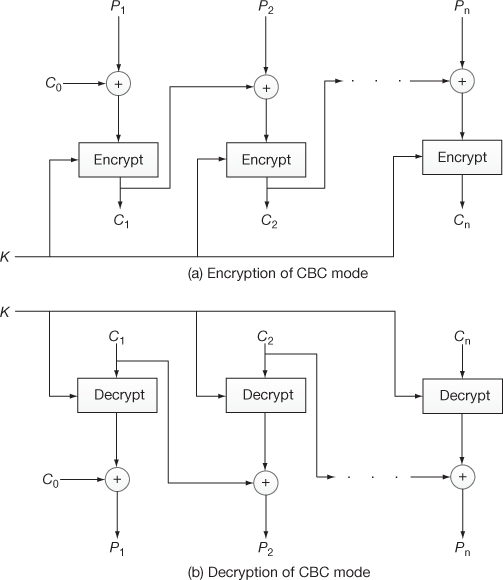
Figure 4.11 Encryption and decryption process of CBC mode
Algorithm 4.2 gives the procedure to perform encryption operations in CBC mode.
4.4.3 Cipher Feedback Mode
The CFB is a stream cipher where s bits (8 bits) are encrypted at a time. In CFB, an IV (C0) is stored in a shift register where shift part has (b – s)-bits and register part has only s bits. In DES, the size of a block b is 64 bits. From these 64 bits, the first 8 bits (SS) are XORed with plaintext (P1) to produce the ciphertext (C1). In general, the encryption and decryption operation for the first block of CFB can be expressed as shown in Equations (4.20) and (4.21). In these equations S denote selection function and s denotes stream size.
 (4.20)
 (4.21)
The encryption and decryption operation for the rest of the blocks of CFB can be expressed as shown in Equations (4.22) and (4.23).
 (4.22)
 (4.23)
Algorithm 4.3 gives the procedure to perform encryption operations in CBC mode.
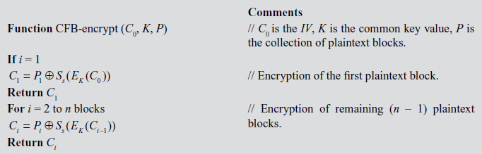
Figure 4.12 shows the encryption and decryption process performed in CFB mode. In this figure, the output of one block is fed as the input to the shift register of next block.
4.4.4 Output Feedback Mode
Output feedback mode (OFB) operates in the same way as that of CFB mode. The main difference between OFB mode and CFB mode is that the selected 8 bits (SS) is supplied as input to the next round in OFB mode. Because, if any bit error occurs in a particular ciphertext, it will be propagated to all the remaining blocks in CFB. To avoid this problem, only the selected s bits of the output produced by the encryption of the previous round will be given as input to the next round in OFB. The encryption and decryption operation for the first round of OFB mode can be expressed as shown in Equations (4.20) and (4.21). The encryption and decryption operation for OFB mode, excluding the first round, can be expressed as shown in Equations (4.24) and (4.25).
 (4.24)
 (4.25)
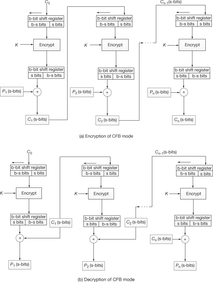
Figure 4.12 Encryption and decryption process of CFB mode
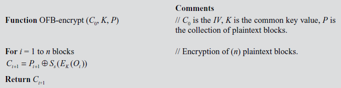
Figure 4.13 shows the encryption and decryption process performed in OFB mode. Here, the output of selected 8 bits is fed as the input to the shift register of the next block. Algorithm 4.4 gives the procedure to perform encryption operations in CBC mode.
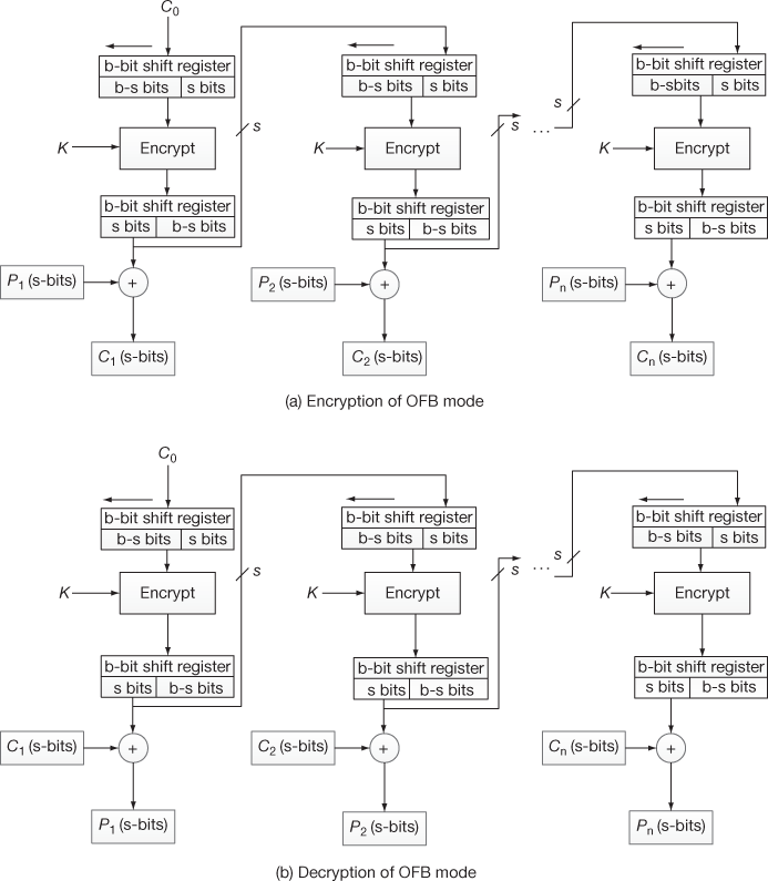
Figure 4.13 Encryption and decryption process of OFB mode
4.4.5 Counter Mode
In this mode, plaintext is divided into n blocks based on the size of the plaintext as shown in Equation (4.14). This method uses the same key value and different counter values for each block of the plaintext. Initially, each counter value is encrypted using the key value K and the resulting value is XORed with the corresponding plaintext to produce the ciphertext value. The encryption and decryption of CTR mode can be expressed as shown in Equations (4.26) and (4.27).
 (4.26)
 (4.27)
where 
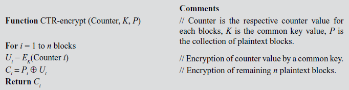
Figure 4.14 shows the encryption and decryption process performed in CTR mode. Here, for each block, individual counters and a common key are used. Algorithm 4.5 gives the procedure to perform encryption operations in CTR mode.
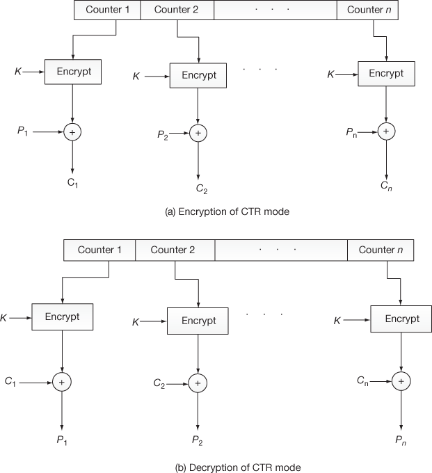
Figure 4.14 Encryption and decryption process of CTR mode
Key Terms
Avalanche effect
Block cipher
Brute-force attack
Chunk
Cipher block chaining (CBC) mode
Cipher feedback (CFB) mode
Common key
Counter (CTR) mode
Counter values
Cryptanalytic attack
Data encryption standard (DES)
Differential cryptanalysis
Electronic code book (ECB) mode
Encryption key generation
Expansion table
Initialization vector (IV)
Inverse permutation
Key expansion
Key generation process
Left circular shift
Linear approximations
Linear cryptanalysis
Output feedback (OFB) mode
Parity checking
Permutation
Primary function
Round operation
S-DES
s bits
Secondary function
Shift register
Stream ciphers
Sub-key
Substitution
Substitution boxes
Swapping
Symmetric block cipher
Summary
- The S-DES algorithm that takes an 8-bit block of plaintext and encrypts is using a 10-bit key to produce an 8-bit block of the ciphertext as output.
- The encryption/decryption of S-DES key expansion phase generates two 8-bit sub-keys from the 10-bit key value that are used in primary and secondary functions.
- In cryptography, a symmetric block cipher is a symmetric key-based deterministic algorithm operating on fixed-length groups of bits, called blocks.
- Block ciphers are important basic components in the design of many cryptographic protocols, and are broadly used to execute the encryption of bulk data.
- For encryption operation, substitution and permutation are the two main techniques used in most secret key algorithms. These techniques are used for a number of times in iterations called rounds.
- There are two inputs to each round one is Li, Ri pair and the other is a 48-bit sub-key which is a shifted and constricted version of the original 56-bit key.
- In the key expansion process, the given 32-bit input is expanded into 48 bits using the expansion table (E-table).
- The data encryption standard (DES) is considered as a predominant symmetric-key algorithm for the encryption of electronic data in previous years. Due to its too small 56-bit key size, DES is now considered to be unsecure for many applications. Even though there are theoretical attacks, the algorithm is assumed to be practically secure in the form of triple DES.
- In cryptography, the word chunk is used to represent a set of data.
- The act of swapping two variables means that mutually exchanging the values of the variables. In DES, at the end of the 16th round, the 32 bits Li and Ri output values are swapped to create the 64-bit pre-output.
- In the key generation process, a 64-bit key is given as the input to permuted choice-1 that removes any 8 bits from the given key value.
- The left circular shift is the operation in which the entries in a tuple are rearranged such that moving the first entry to the final position.
- A small change in the plaintext or the key should affect many bits in the ciphertext and is called Avalanche effect.
- In cryptography, potential attack is any effort to demolish, disclose, modify, prevent and gain unauthorized access against intended information and users.
- In cryptography, a brute-force attack is used against any encrypted data. In this attack, the attackers systematically check all possible key values until the correct one is found.
- In cryptography, differential cryptanalysis is performed based on the chosen plaintexts meaning that the invader should be able to find ciphertexts from a set of chosen plaintexts.
- • Linear cryptanalysis is also a general form of cryptanalytic attack based on finding linear approximations to the action of block ciphers. Due to the public knowledge of differential and linear cryptanalysis, the new designs are expected to be developing the algorithm which is resistant to these attacks, and many, including the advanced encryption standard which has been provided secure against the attack.
- A stream cipher is a symmetric key cipher in which a cryptographic key is applied to each binary digit in a plaintext data stream to produce a ciphertext, one bit at a time.
- For encryption operation, permutation is one of the main techniques used in most secret key algorithms. Permutation is a process of reordering of the bit positions into some confused format.
- In cryptography, cryptanalytic attack is a kind of attack in which the cryptanalyst tries to decrypt new pieces of ciphertext without any additional information. The main aim for a cryptanalyst is to find out the secret key.
- In mathematics, a linear approximation is a general function which is an approximation of a linear function.
- To provide the facility of encrypting large amount of data using the DES algorithm in various applications, NIST developed five modes of operation for the DES algorithm in the year 1981.
- Electronic code book (ECB) and cipher block chaining (CBC) modes are used for block ciphers.
- Cipher feedback (CFB) and output feedback (OFB) modes are used for stream ciphers.
- Counter (CTR) mode is used for both block ciphers and stream ciphers.
- In ECB mode, each block of the plaintext is independently encrypted with a common key (K) to produce different ciphertext for each plaintext.
- In CBC mode, first ciphertext (C1) and second plaintext (P2) are XORed and then the resultant value is encrypted using a common key (K) to produce the second ciphertext (C2).
- The CFB mode is a stream cipher where s bits (8 bits) are encrypted at a time.
- In OFB mode, only the selected s bits of the output produced by the encryption of the previous round will be given as input to the next round.
- In CTR mode, the same key value and different counter values are used for encrypting each block of the plaintext.
Review Questions
- Write short notes on S-DES key generation process.
- Explain about S-DES encryption and decryption process in detail.
- What is the difference between a block cipher and a stream cipher?
- What is the purpose of the S-boxes in DES?
- Consider a cipher composed of 16 rounds with an input bit block length of 64 bits and a key length of 64 bits. Input bits: 10101010 10101010 10101010 10101010 10101010 10101010 10101010 10101010; Key bits: 00111011 00111000 10011000 00110111 00010101 00100000 11110111 01011110. From the input bits and keys, find out the first eight round sub-keys.
- What is the total number of exclusive-or operations used in DES?
- What is the purpose of the permutation in DES?
- Explain about single round operation of DES in detail.
- How triple DES enhances performance compared to the original DES?
- Differentiate S-DES and DES.
- What is the difference between differential and linear cryptanalysis?
- What is meant by cryptanalytic attack?
- Explain about five modes of operations in detail.
- Differentiate CFB and OFB modes.
References
- http://www.cs.uri.edu/cryptography/dessimplified.htm
- 2. http://mercury.webster.edu/aleshunas/COSC9205130/G-SDES.pdf
- Data encryption standard (DES). National institute of standards and technology (NIST).
- William E. Burr, ‘Data Encryption Standard’, in NIST’s anthology ‘A Century of Excellence in Measurements, Standards, and Technology: A Chronicle of Selected NBS/NIST Publications, 1901–2000.
- Kaisa Nyberg (1991). ‘Perfect nonlinear S-boxes’. Advances in Cryptology - EUROCRYPT ‘91: 378–386.
- Coppersmith, Don. (1994). The data encryption standard (DES) and its strength against attacks at the Wayback Machine (archived June 15, 2007). IBM Journal of Research and Development, 38(3), 243–250.
- Biham and Shamir, 1993, pp. 8–9.
- Matsui, M. and Yamagishi, A. ‘A new method for known plaintext attack of FEAL cipher’. Advances in Cryptology – EUROCRYPT 1992.
- www.utdallas.edu/~muratk/courses/crypto09s_files/modes.pdf