Table of Contents for
NoSQL and SQL Data Modeling: Bringing Together Data, Semantics, and Software
 NoSQL and SQL Data Modeling: Bringing Together Data, Semantics, and Software
Published by
Technics Publications, 2016
NoSQL and SQL Data Modeling: Bringing Together Data, Semantics, and Software
Published by
Technics Publications, 2016
- cover
- NoSQL and SQL Data Modeling
- FrontMatter
- FrontMatter-1
- FrontMatter-2
- FrontMatter-3
- Acknowledgements
- Introduction
- Part I Real Words in the Real World
- Chapter 1 It’s All about the Words
- Chapter 2 Things: Entities, Objects, and Concepts
- Chapter 3 Containment and Composition
- Chapter 4 Types and Classes in the Real World
- Part II The Tyranny of Confusion
- Chapter 5 Entity-Relationship Modeling
- Chapter 6 The Unified Modeling Language
- Chapter 7 Fact-Based Modeling Notations
- Chapter 8 Semantic Notations
- Chapter 9 Object-Oriented Programming Languages
- Part III Freedom in Meaning
- Chapter 10 Objects and Classes
- Chapter 11 Types in Data and Software
- Chapter 12 Composite Types
- Chapter 13 Subtypes and Subclasses
- Chapter 14 Data and Information
- Chapter 15 Relationships and Roles
- Chapter 16 The Relational Theory of Data
- Chapter 17 NoSQL and SQL Physical Design
- Part IV Case Study
- Chapter 18 The Common Coffee Shop
- APPENDIX COMN Quick Reference
- Glossary
- Photo and Illustration Credits
- Index
|
|

“The Unified Modeling Language (UML) is a general-purpose visual modeling language that is used to specify, visualize, construct, and document the artifacts of a software system.” [Rumbaugh 1999, p. 3] Although the UML’s first purpose was for the modeling of software, the UML’s class diagrams (just one of about nine kinds of diagrams in the UML) have been used to model data and databases. The UML Database Modeling Workbook[Blaha 2013] describes how to use UML along with E-R modeling to design databases.
Class Diagrams
A UML class diagram uses simple rectangles, divided into three sections, to represent classes of objects. See Figure 6-1 below. (For an E-R equivalent, see Figure 5-1 in chapter 5.) The top section of the rectangle gives the name of the class. The middle section lists the attributes of the class. The bottom section, which in Figure 6-1 is empty in all three classes, lists the operations of the class. Not shown on a UML class diagram are the methods of the class, which are the software routines that implement a class’s operations.
In an object-oriented software system, the methods of a class are ordinarily the only routines that have direct access to the attributes of objects of that class. This kind of restriction is called encapsulation, and represents one of the most valuable contributions that object-oriented software design has made to the reliability of software. By limiting the routines that can operate on attributes, it is much easier to ensure that the totality of the routines in any software is operating correctly.
However, data in a database is not (or should not be) encapsulated, at least not while it resides in a database management system. The reasons for this are covered in chapter 12. The UML provides a notation to indicate whether a class attribute is encapsulated. If an attribute’s name is preceded by a minus sign, then the attribute is encapsulated and can only be accessed by the class’s methods. If the name is preceded by a plus sign, then any routine can access the attribute. All of the attribute names of the classes in Figure 6-1 are shown with + signs preceding them, indicating that these attributes are not encapsulated.
Each object of a class has a “slot” to hold the value of each attribute of its class. The term “slot” is used by the UML but never defined. Reading between the lines, we conclude that a “slot” is a part of a computer’s memory that is allocated to an object.
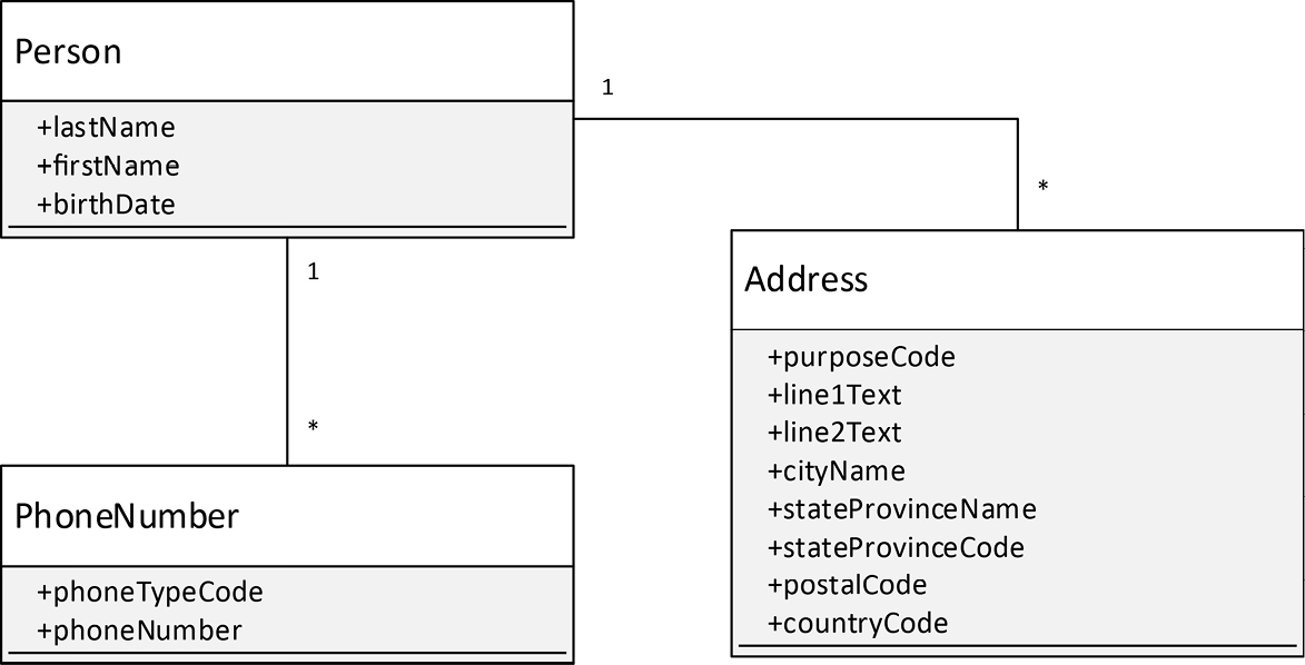
Figure 6-1. A UML Model of Data
The lines between the class rectangles in Figure 6-1 express what the UML calls associations. They indicate that objects of the classes will have “connections” to each other. Just as objects are instances of classes, links are instances of associations. Just as an object has a slot to hold the value of each class attribute, a link has a slot to hold a reference to each object at the ends of the association. For example, a link that is an instance of the association between a Person object and one or more Address objects would have exactly one reference to the Person object and one or more references to Address objects.
Stereotyping
A stereotype is “a new kind of model element defined within the model based on an existing kind of model element.” A stereotype appears on a model as a name enclosed in guillemets ( « » ). Stereotyping is the UML’s main mechanism for extending the language beyond what is already built in.
Limitations of the UML
In the original conception of the UML as a language for specifying software, associations were conceived to be implemented as references between objects in a computer’s memory. Those references are generally implemented as pointers. However, pointers do not translate well to databases. Early database management systems used pointers to represent data relationships, but they were difficult to maintain and did not perform well, and were eventually retired in favor of the now-dominant SQL database management systems, which use foreign keys to represent data relationships.
The UML does not have a notation for identifying key attributes, and therefore cannot represent foreign keys. This means that the UML cannot fully specify a database design. There are workarounds for this deficiency. Michael Blaha in the UML Database Modeling Workbook[Blaha 2013] lays out an approach where diagrams in the UML are used for higher-level database design, and then database-specific details, including keys, are specified using the Information Engineering (IE) variant of entity-relationship (E-R) data model notation.
Thus, as a graphical notation for database design, the UML cannot stand on its own.
Middling Level of Abstraction
The UML is aimed at just about the same level of abstraction as an object-oriented program. The classes of the UML and of a program are both analogous to similarly named real-world entity types (concepts and real-world objects).
One can use the UML to denote real-world classes and real-world objects, provided that one makes it clear in notes on a diagram as to which classes and objects should be interpreted as existing in the real-world and not in a computer’s memory.
The UML depends on the notion of a “slot” which it does not define. The UML also does not enable the depiction of a “slot” in any of its graphical symbols. This is a pretty clear indication that the UML considers lower-level physical implementation details to be taken care of by things that should not be diagrammed. This approach makes it difficult to use the UML to express implementation details with the rigor and completeness necessary for model-driven development. It also requires the assistance of other notations, such as E-R, for complete specification of a database design.
Lack of Concept
The UML defines an object as “a discrete entity with a well-defined boundary and identity that encapsulates state and behavior; an instance of a class” [Rumbaugh 1999, p. 360]. It defines a class as “the descriptor for a set of objects.” [ibid., p. 185]
This is all well and good, but the UML lacks any ability to describe entities that do not have state or behavior; that is, concepts. Concepts are expressible in the UML, but only implicitly and only in connection with classes, objects, or other things that the UML can express.
Concepts appear frequently in requirements, and an inability to model them directly means that a model can only represent things related to a concept. For example, an order is a concept. A model often focuses on the record of an order, which can be represented in the UML, but the order itself is just the idea that a customer has made a request of a supplier, and the order might not even be recorded—it might merely be spoken. Another important concept to represent is that of a role played by an actor. In the examples given in writings about the UML, a role is a structural piece of some object, rather than a concept independent of any object. Actors, such as humans, can take on and shed many roles, and the inability to model this apart from an object seems rather limiting.
If one needs to represent a concept and how it, and not a record of it, relates to other concepts in the problem space, one will need to use stereotyping. It seems that something as basic as “concept” ought to have a direct representation in a modeling notation.
Subclassing versus Subtyping
In The Unified Modeling Language Reference Manual [Rumbaugh 1999], the term “supertype” is explicitly called out as a synonym for “superclass”. Strangely, the term “subtype” is not similarly called out as a synonym for “subclass”. Perhaps this is merely an omission in the documentation.
As we will see in chapter 13, subtypes and subclasses are very different, and therefore so too are supertypes and superclasses.
Terminology
One of the chief challenges I find when trying to apply the UML is that several key UML terms have repurposed ordinary English words in ways that seem strange, given their ordinary meanings.
Relationship, Composition and Aggregation
The UML defines a relationship as “a reified semantic connection among model elements. Kinds of relationships include association, generalization, metarelationship, flow, and several kinds grouped under dependency” [Rumbaugh 1999, p. 411]. Thus, the UML term “relationship” is an over-arching category of various types of connections between model elements.
In contrast, a relationship in COMN is simply an assertion that is true or false (that is, a proposition) about two or more entities. The entities involved in the relationship are “semantically connected” by virtue of being referenced by the same proposition. Chapter 15 examines relationships in depth. Relationships are foundational to semantics.
Although the UML has a concept called “aggregation”, it is explicitly ill-defined, and called a “modeling placebo” [Rumbaugh 1999, p. 148], intended to pacify those who claim that it is important. Apparently there is no consensus among those who think it is important as to what it means.
In contrast, in ordinary English the term “aggregate” refers to a composite material, such as concrete, where the components of the aggregate retain their integrity, but there is little chance that they can be separated again. This is exactly how COMN uses the term.
Despite aggregation being ill-defined, composition is defined in terms of aggregation as “a form of aggregation association with strong ownership and coincident lifetime of parts by the whole” [Rumbaugh 1999, p. 226]. Once again reading between the lines, one gets the impression that several objects related by composition are joined in the sense of an assembly, where the objects may be joined or removed, with the additional proviso that, if one of the assembled objects is destroyed, all of the objects in the assembly are destroyed.
Type and Implementation Class
In the UML, a type is a stereotype of a class, meaning that it is a class used in a restricted way, merely to specify a subset of objects. An implementation class is another stereotype of a class, and effectively restricts the class to correspond to a programming language class.
COMN has type, which is a fundamental classifier and specifies a set of anything, be it a set of concepts or a set of objects. It corresponds approximately to a UML type stereotype, but can specify more than just sets of objects. COMN has class, which is effectively an implementation class.
UML Terms Mapped to COMN Terms
A mapping from UML terms to the corresponding COMN terms is given in the table below. Where two COMN terms are given for a single UML term, it indicates that the UML term is ambiguous.
|
UML Term |
COMN Term |
|
class |
class or type |
|
implementation class |
class |
|
attribute |
component of a type or class; possibly a data attribute |
|
type stereotype of class |
type |
|
data type |
type where the members of the type are simple concepts |
|
“slot” |
object component of a class |
|
relationship |
no direct equivalent; see the various kinds of UML relationships listed below |
|
association |
relationship |
|
no UML equivalent |
composition, which is the over-arching term for the formation of composite things from component things |
|
composition |
assembly with the additional constraint that destruction of one component leads directly to destruction of all components |
|
aggregation |
ill-defined in the UML, so no COMN equivalent |
|
no UML equivalent |
aggregation, which is the form of composition of the components (UML attributes) of a type or class |
|
Key Points
|
References
[Rumbaugh 1999] Rumbaugh, James, Ivar Jacobson, and Grady Booch. The Unified Modeling Language Reference Manual. Reading, Massachusetts: Addison-Wesley, 1999.
[Blaha 2013] Blaha, Michael. UML Database Modeling Workbook. Westfield, New Jersey: Technics Publications, LLC, 2013.