Table of Contents for
NoSQL and SQL Data Modeling: Bringing Together Data, Semantics, and Software
 NoSQL and SQL Data Modeling: Bringing Together Data, Semantics, and Software
Published by
Technics Publications, 2016
NoSQL and SQL Data Modeling: Bringing Together Data, Semantics, and Software
Published by
Technics Publications, 2016
- cover
- NoSQL and SQL Data Modeling
- FrontMatter
- FrontMatter-1
- FrontMatter-2
- FrontMatter-3
- Acknowledgements
- Introduction
- Part I Real Words in the Real World
- Chapter 1 It’s All about the Words
- Chapter 2 Things: Entities, Objects, and Concepts
- Chapter 3 Containment and Composition
- Chapter 4 Types and Classes in the Real World
- Part II The Tyranny of Confusion
- Chapter 5 Entity-Relationship Modeling
- Chapter 6 The Unified Modeling Language
- Chapter 7 Fact-Based Modeling Notations
- Chapter 8 Semantic Notations
- Chapter 9 Object-Oriented Programming Languages
- Part III Freedom in Meaning
- Chapter 10 Objects and Classes
- Chapter 11 Types in Data and Software
- Chapter 12 Composite Types
- Chapter 13 Subtypes and Subclasses
- Chapter 14 Data and Information
- Chapter 15 Relationships and Roles
- Chapter 16 The Relational Theory of Data
- Chapter 17 NoSQL and SQL Physical Design
- Part IV Case Study
- Chapter 18 The Common Coffee Shop
- APPENDIX COMN Quick Reference
- Glossary
- Photo and Illustration Credits
- Index
|
|

Entity-relationship (E-R) modeling was formally proposed by Peter Chen in 1975 [Chen 1976], and is almost certainly the dominant form of data modeling in use today. The notation of E-R modeling has evolved significantly since Chen’s paper, and has forked into several variants, including Integration DEFinition for Information Modeling (IDEF1X), Barker-Ellis, Information Engineering (IE), and other variants. IE notation is common but not standardized, and exists in several variants. For the purposes of this chapter, we will use the variant of IE notation implemented in a Microsoft Visio drawing tool stencil.
E-R modeling defines three stages of data modeling: conceptual, logical, and physical. We will start our review of E-R modeling with logical data models, where the focus is on the design of data structures to hold data relevant to the problem to be solved.
Logical E-R Data Models
A logical E-R data model starts with simple rectangles representing data that is to be stored about various things, and lines between rectangles representing relationships expressed in data. See Figure 5-1 below. (For the UML equivalent, see Figure 6-1 in chapter 6.) Most E-R data modelers refer to the rectangle as an entity. This is not incorrect, because it’s never wrong to call anything a thing. But this terminology covers up the fact that the rectangle represents up to three things simultaneously:
- The rectangle represents a logical record type. This is not a type in the sense of a generalization/specialization hierarchy. It is a type in the sense that it designates a set. A logical record type is a list of data attributes aggregated together, and it implicitly designates the set of all possible values of those data attributes taken together—the Cartesian product of the data attributes’ types. Sometimes the display of these data attributes is suppressed, and only the name of the entity is visible, but the rectangle represents the data attributes nonetheless.
- The rectangle represents a table of data conforming to the logical record type, which presumably is or will be created in keeping with the model.
- By labeling a rectangle with the name of a real-world entity type—for example, “Person”—an implicit connection is made from the rectangle to the real-world entity type that records of this type are about. Not every entity rectangle relates directly to a real-world entity type. Some entities are needed just to relate some data to some other data.
For those readers familiar with E-R modeling, the most important idea to take away from this chapter is that the entity of E-R modeling in fact denotes a logical record type, a table of data, and possibly also a real-world entity type. In ordinary English, the word entity means an individual thing—what an E-R modeler would call an instance or an entity instance—not a type of thing nor a table of data. COMN uses the term entity to mean an instance, and entity type to mean a type of thing (generally, though not always, a type of real-world thing).
An entity rectangle is divided into three sections. The top section gives the name by which the “entity” (logical record type/table/real-world entity type) is known in the model. The middle and bottom sections list data attributes. The middle section lists the logical record type’s identifying data attributes, which make up its primary key. These are the data attributes whose values are unique on each record of the type in a single table, and thus serve to identify individual records. The “PK” designation indicates exactly which data attribute (or data attributes) form the primary key for records of the type in a single table. The bottom section lists the ordinary data attributes of the logical record type.
Some of the data attributes are so-called foreign keys: data attributes which are keys to other logical record types. It is a foreign key that represents a relationship between two entities. In fact, the relationship is between the data in the two tables. Foreign key data attributes are indicated by an “FK” designation. In the data model of Figure 5-1, the Person ID data attribute of both the Person Phone Number and Person Address tables are foreign keys that reference the Person ID primary key of the Person table.
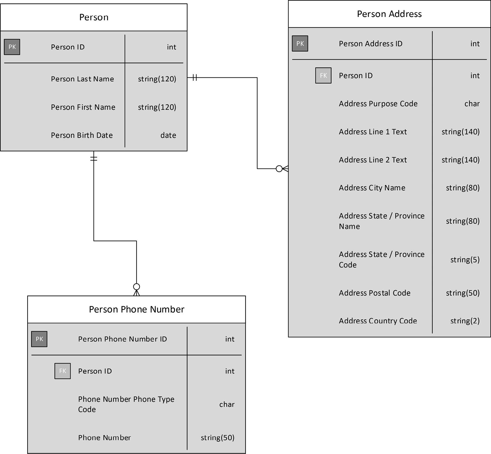
Figure 5-1. A Logical E-R Data Model
The relationship lines connecting the rectangles use what is called “crow’s feet” notation, and indicate how many records matching a foreign key are found in the table at each end of a relationship. Two lines crossing a relationship line mean “one and only one” record at that end. In Figure 5-1, the Person ID of each Person Address record references only one Person record. This makes sense, since Person ID is the primary key of the Person table. A primary key value is always unique and will always reference exactly one record. Reading the same relationship line in the other direction, we see a circle and then what look line three lines fanning out to the Person Address record. The circle indicates optionality, and the three lines indicate “many”. This indicates that one Person record may be referenced by any number of Person Address records, including none.
It should be pointed out that the model of Figure 5-1 is not ideal, because it creates the possibility that the same data might be stored repeatedly in a database. For instance, two people who live at the same address will have Person Address records that are identical except for the Person ID foreign key values. But this design has been chosen to illustrate issues relevant to COMN, so, for now, please ignore these otherwise important design issues.
Multiple Levels of Abstraction
It is customary to use E-R data models at three levels of abstraction:
- conceptual (the highest level)
- logical
- physical (the lowest level)
Each rectangle in a conceptual data model may relate to one or more rectangles in a logical data model, and each rectangle in a logical data model may relate to one or more rectangles in a physical data model.
A conceptual data model is similar to a logical data model, in that each rectangle represents a logical record type and eventually a table whose records conform to that type. But a conceptual data model simplifies a logical data model in two important ways:
- It is customary to hide the display of data attributes within the rectangles of a conceptual data model, in order to allow the modeler to focus more on the relationships between entities.
- A conceptual data model will depict many-to-many relationships between entities with a simple relationship line. In a logical data model, such many-to-many relationships are “resolved” by inserting an associative entity between the pair.
A conceptual data model is usually developed as a first-order approximation of a logical data model. Data-related details are omitted in order to support the early stages of model development, where too much attention to data-related details could distract from the task of documenting the data requirements that are present in a given set of business requirements. The conceptual data model is then used to derive a logical data model, where details such as data attributes and associative entities are added.
With just a little training, non-technical personnel can interpret and interact with conceptual data models. When interviewing business stakeholders, a conceptual E-R data model is a useful tool for capturing data requirements, validating terminology, and scoping application efforts.
Lower in the layers of abstraction, a physical data model enables the expression of the details of how a data design will be implemented in a particular database management system (DBMS). A rectangle in a physical data model no longer represents a logical record type, but rather a physical record type as the layout of a row in a table. A list of names and data types inside the rectangle expresses the names and types of the table’s columns. The names of tables and columns are spelled in a way that is dictated by the technical requirements of the chosen DBMS; the most noticeable difference from names in the logical data model is that physical data names do not usually contain spaces.
Just as a logical data model can contain associative entities that are not depicted in a conceptual data model, a physical data model can contain tables that are not represented in a logical data model; for example, a physical data model might include tables that combine data from multiple logical data model entities for faster read access. In a disciplined data modeling process, such tables are limited solely to those needed for some implementation purpose, and do not represent a short circuiting of the logical data modeling process.
This approach to modeling at three levels of abstraction can be thought of as a stack of five planes. The uppermost plane is where most of the things mentioned in business requirements are to be found. This plane is called the real world. The next plane down is inhabited by the conceptual data model. Many entities in the conceptual data model correspond to real-world entities, and are named so as to reflect that fact. The middle plane is inhabited by the logical data model. Most of the entities and their relationships on this plane correspond one-for-one to those on the conceptual data model plane. As mentioned above, some logical data model entities correspond to many-to-many relationships from the conceptual data model. The next plane down is inhabited by the physical data model. Again, most things correspond one-for-one to the things on the next higher plane. Finally, the bottom-most plane is the database implementation. In a fully model-driven database implementation, everything in the database has a one-for-one correspondence to something in the physical data model. In fact, there are data modeling software tools available that support the generation and maintenance of SQL databases directly from physical data models. These tools make possible the ideal of model-driven development, where a connection can be maintained between the business requirements captured in the conceptual data model, through the several planes of modeling, all the way to the tables of the database.
Limitations of E-R Modeling Notation
The disciplined use of E-R modeling notation has enabled many database design processes to progress efficiently and correctly from requirements analysis through data design and all the way into implementation, following a model-driven development process all along the way. E-R notation has been a workhorse of the information technology (IT) industry in this regard. But E-R notation does have limits that prevent it from fully expressing some valuable aspects of database design, as we shall now see.
NoSQL Arrays and Nested Data Structures
Logical and physical E-R notation assumes that database implementation will be in a DBMS, such as a SQL DBMS, that stores data in tables. It does not, therefore, have any way of expressing two modes of data storage that NoSQL databases make possible:
- arrays
- nested data structures (often called “nested documents” by NoSQL DBMSs)
Arrays can be useful ways for storing some small and simple data structures. For example, it might be preferable to store a person’s list of telephone numbers directly as an array attribute on the Person entity of Figure 5-1. This avoids the overhead of a separate table and foreign key just to store phone numbers. (If one is to do this, one must consider whether the telephone numbers need an index to support fast searching, and, if so, whether the NoSQL DBMS chosen for implementation can index array-type data attributes. We’ll look at that question in greater depth in chapter 17.) E-R notation has no way to express an array.
We’ll look at nested data structures in the next section.
Both arrays and nested data structures are modeled in E-R notation in a way that corresponds to their necessary implementation in a SQL database. This is what is shown earlier in Figure 5-1. The array or nested data structure is split out into its own table. That table has a foreign key back to the table from which it was split. Additionally, that table must have its own primary key.
NoSQL DBMSs support the direct aggregation of arrays and nested data structures in enclosing data structures, without the use of keys. E-R notation has no way to show data structures that are related to each other without keys. As a result, E-R notation cannot be used for NoSQL database design.
Some organizations have nonetheless used E-R notation for NoSQL designs, and use notes or other means to communicate to humans that a relationship line between two entities / logical record types does not represent a foreign key relationship. Such models can be useful, but cannot be used in a model-driven development of a NoSQL database, because the modeling tool can’t tell the difference between foreign-key relationships and aggregation of arrays or nested data structures in a single “entity”. Such models also require extra discipline on behalf of the data modeler, to make sure that the meaning of the non-foreign-key relationships is preserved as the model is updated, since the modeling tool used can’t know the difference.
Lack of Reusable Composite Types
Consider the Person Address logical record type of Figure 5-1. Most of the data attributes of this logical record type are not specific to persons, but are related only to postal addresses. The only person-specific data attributes are the keys, and these would not be present in a NoSQL database design that nested this information. If one removed these person-specific data attributes, one would have a generic postal address type, which could be used to store the addresses of persons, organizations, factories, ports, government entities—in other words, any postal address. This would clearly be quite useful.
However, in the current state of things, individual E-R data models must specify the structure of postal address data over and over. A modeler could define a domain to capture the types of individual data attributes. For instance, it might make sense to define a domain called Address Line Text as string(140), and then reuse this domain to specify the types of Address Line 1 Text and Address Line 2 Text. But this works only at the level of an individual data attribute. The type of an individual data attribute in an E-R model is always what we call a simple type, because it has no components. There is no way to create what is called a composite type that has multiple components—such as the entire postal address structure—and then include it by name in many designs. Programmers for decades have had the concept of a subroutine, which enables a routine written just once to be incorporated without alteration in hundreds of programs, saving development and debugging time, and making implementations more consistent with each other. But in the world of E-R modeling, the work of designing common data structures and integrating them into multiple models is done repeatedly, wasting time and making results less consistent.
Remember that a rectangle in a logical E-R data model represents a logical record type and a particular set of records that conform to that type. There is sometimes a debate as to whether the rectangle should be named after the type (for example, the singular Postal Address) or the set of records (for example, the plural Postal Addresses). The established convention is to name the rectangle in the singular, after the type. If the modeler wants to refer to the set of records and not the type, he must say so, and this isn’t a problem in conversation. But there’s no way to distinguish between the two in a logical model. There is therefore no way for an E-R modeler to say, “This rectangle represents just a type and not any particular set of records,” which would define a reusable composite type.
The relational database mentality behind E-R notation explains why this limitation has been so persistent. One of the main goals of relational database design is to eliminate redundancy in data, which is where the same data is stored in several places in the database. Redundancy leads to the possibility of inconsistent data, where an update of certain data in the database changes the logically identical data items in one physical place but leaves them out of date in another. Inconsistent data is devilishly hard to deal with, reduces the quality of data, and can lead to costly operational mistakes as fundamental as shipping a package to the wrong address.
On the surface, it appears that supporting composite types in E-R notation would enable redundant data in spades. A simplistic use of composite types would certainly do that. But there are many cases where legitimate uses of composite types would make designs simpler and more robust. As we have seen, being able to specify the structure of a postal address just once, and then incorporate that structure in many places, perhaps in models for multiple databases, could be quite useful.
Composite types are especially useful when the data to be represented has a structural pattern but there is no benefit to organizing that data around a key. Consider the logical data model of Figure 5-2, which depicts a foreign exchange transaction. A foreign exchange transaction is a financial transaction in which one exchanges the currency of one nation for the currency of another. For instance, one might exchanges euros for British pounds, or American dollars for Canadian dollars.
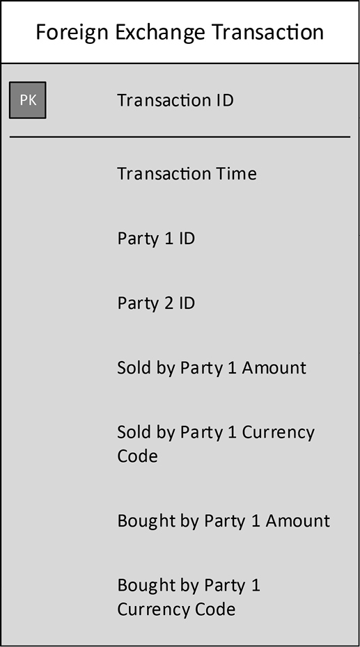
Figure 5-2. A Foreign Exchange Transaction E-R Entity
As the model shows, a record of a foreign exchange transaction needs to show:
- the amount and currency that was “bought” or taken in
- the amount and currency that was “sold” or given out
- the identity of the “counterparty” who provided the currency that was bought and accepted the currency that was sold
- the date and time, or “timestamp”, of the transaction
There is a clear pattern in the data attributes. Two pairs of data attributes are highly similar in their structure and naming, specifically the two pairs of currency amount and currency code. Each pair is in effect a use of an unnamed composite type, which perhaps we could call “Currency and Amount”. Since E-R notation has no way to identify, name, and reuse composite types, we must content ourselves with naming the individual data attributes in a way that reflects that the amounts and currency codes are in pairs.
We know intuitively that an amount and a currency are related in a special way, but we have no way of depicting this directly in an E-R model. This is a deep subject, especially so for those database designers who have known only E-R notation and SQL DBMSs. Chapter 12 is devoted to an in-depth exploration of composite types and their representation in COMN data models.
Lack of Place
An E-R model is meant to illustrate the design of a single database, which is implemented in a single place. But the reality in almost all cases is that, at any one time, data belonging to a single logical record type can be found in multiple physical records, in multiple databases. A major task of enterprise data management is to get one’s arms around this reality, to identify the one physical place which is to be used as the authoritative source for a given type of data, and then to ensure that all other records of the same type of data take their data from the authoritative source. An E-R model, with its one-for-one mapping from logical record type to physical table, cannot represent the complexities of this reality. It is not possible in an E-R model to show that a single logical record type has multiple instantiations in multiple databases. E-R notation is limited to depicting one database at a time.
Modeling the Real World
As we have seen, the so-called entities of conceptual and logical E-R data models are typically given names that imply the real-world entity types that they are about. Consider our logical data model above which has a logical record type named “Person”. The name of the logical record type clearly implies that records of this type hold data about the real-world entity type known as “person”.
Sometimes data modelers will add so-called entities to a conceptual model to depict things in the problem space about which no data will be stored. These are in fact not logical record types at all, but are actually real-world entity types. Data modeling tools enable a data modeler to tell the tool not to carry such “entities” forward to the logical data model, but no visual indication is given that the symbol does not represent a logical record type. This shows that it would be very useful if E-R notation could graphically distinguish real-world entity types from logical record types.
Representing Individual Entities
If one wishes to connect one’s data model to the real world, it can be very important to represent, not only real-world entity types, but also particular instances of those types—particular entities—and relationships to data about those instances. For instance, a model of the legal system of the United States would need to include an entity type called “Court”, but may need to represent the Supreme Court, which is an entity and not an entity type, since it is a very special one-of-a-kind court. The model would need to show relationships between the Court logical record type and a particular record representing the Supreme Court—but it can’t. An E-R model can represent “Court” but not “the Supreme Court”. Such individual entity instances are left implicit in a model, and there is an unsatisfied need to show that records of a certain type always connect to data about those implicit entity instances.
Mapping Between Models
As we have seen, the five planes of modeling—from the real world, through E-R data models at three levels of abstraction, to the physical database implementation—have mappings between them which are one-to-one or very close to one-to-one. The mappings are controlled by simple rules and are relatively straightforward.
E-R notation does not have a notation for expressing these mappings. This is not a problem except when the mappings between layers are not simple. For example, it may be decided that a single physical table will be used to represent data from three logical record types, representing a decision to denormalize data for faster read access. The logical data model can represent the three logical record types, the physical model can represent the one combined table, but there is no way to express the mapping from the one table back to the three logical record types. You can think of that mapping as lost between the planes. When denormalization is required, or when novel NoSQL data organization methods result in the physical layer not being mapped one-to-one to logical record types, the need to show the mapping increases.
Data in Software
E-R notation was developed in order to support the design of databases. As such, it did not take into account any of the needs of software development. Software developers cannot use E-R notation to represent their software designs. This leaves quite a gap between the modeling notation used by database developers and the modeling notations or languages of software developers.
Terminology
Let’s review the terms that E-R modeling has specialized, and compare them to their ordinary English meanings and their use in COMN.
Entity
As we have seen above, the E-R term “entity” can mean any of the following things:
- a logical record type
- a set of records that conform to the logical record type
- (in a conceptual model) a real-world entity type
Calling a logical record type an entity is convenient shorthand, and can’t be called incorrect, since the term “entity” just means “thing”, and everything is a thing. But it only works because E-R notation cannot express the idea of individual things, but only types of things—specifically, types of logical records. Taking the ordinary term for thing—entity—and using it to mean a type of logical record or a set of records makes it difficult or impossible to talk about individual records.
In a conceptual model, an E-R entity may represent a type of real-world thing. Again, this makes it difficult to model or discuss an individual thing.
As will be seen in Part III of this book, it can be very valuable to be able to talk about individual things, not just types of things.
As mentioned above, the presence of a so-called “entity” in an E-R data model implies that there is or soon will be a table of records in a database corresponding to the entity of the model. Thus, the rectangle of an E-R model has a number of explicit and implicit meanings, depending on the kind of model in which it is found and the context in which it is discussed. E-R notation does not make it possible to indicate the exact meaning using a graphical symbol.
Conceptual
As mentioned, the meaning of the term “conceptual” in “conceptual data model” is used to mean “first approximation” of a logical data model. This is analogous to the use of “concept” in an “artist’s concept drawing” of a building: it’s just supposed to give the viewer a preliminary idea or “concept” of the final result.
Using “conceptual” this way makes it more difficult to talk of “concepts” in distinction to “objects”. Both are important when discussing data, as data exists both as concepts (at the logical level of abstraction) and as objects (at the physical level of abstraction). When using the word “conceptual”, we must pay close attention to the context. A concept can be a very precise thing, and treating “conceptual” as a synonym for “approximate” can prevent us from seeing the intended precision.
E-R Terms Mapped to COMN Terms
A mapping from E-R terms to the corresponding COMN terms is given in the table below. Where more than one COMN term is given for a single E-R term, it indicates that the E-R term is ambiguous.
|
E-R Term |
COMN Term |
|
logical record type, which is a kind of composite type |
|
|
entity |
table of logical records |
|
(possibly) real-world entity type |
|
|
instance |
entity |
|
data type |
simple type |
|
domain |
simple type |
|
data attribute |
data attribute; more generally, component of a composite type |
|
(no equivalent) |
composite type |
|
conceptual |
approximate |
|
(no equivalent) |
conceptual: relating to a concept or concepts |
|
Key Points
|
References
[Chen 1976] Chen, Peter Pin-Shan. “The entity-relationship model—toward a unified view of data.” ACM Transactions on Database Systems (TODS), 1, 1. New York: Association for Computing Machinery, 1976.