Table of Contents for
Node.js for Embedded Systems
 Node.js for Embedded Systems
Published by
O'Reilly Media, Inc., 2016
Node.js for Embedded Systems
Published by
O'Reilly Media, Inc., 2016
- Cover
- nav
- Node.js for Embedded Systems
- Node.js for Embedded Systems
- Foreword
- Preface
- 1. Connecting Worlds
- 2. Blink with Arduino
- 3. Espruino
- 4. The Tessel 2
- 5. Particle Photon
- 6. Single-Board Computers
- 7. Components for Prototyping
- 8. Node.js Libraries for Hardware
- 9. Exploring Network Protocols
- 10. Web Frontends for Things
- 11. Entering the Cloud
- 12. Making Robots with Node.js
- 13. Wireless Data with Bluetooth
- 14. Toward the Physical Internet
- 15. From Products to Toolkits
- A. Node.js
- B. Early Hardware for IoT Systems
- Index
- About the Authors
- Colophon
Chapter 7. Components for Prototyping
The components you select define what hardware devices you can build. To add components to devices, it is important to understand how to build basic electronic circuits.
Circuits and components are the topics of this chapter. Because entire books are written about this (one important one is Paul Horowitz’s Art of Electronics [Cambridge University Press, 2015]), the material we’ll cover here focuses in particular on prototyping and experimentation on systems. The overview about electronic parts should also help you to better follow programming examples in later chapters.
If you are new to hardware, your first experiences with circuits and components can be daunting. In this case, you might want to learn with Tessel modules first. With Tessel modules, you get circuits and components that you can plug into your Tessel without the pain (or joy) of debugging an electronic setup. You can easily make your own Tessel modules once you get familiar with electronics. If you do, you can share your new module with the Tessel community, and thousands of people around the world could benefit from your work.
Wiring Circuits
Working with embedded devices requires you to gain some understanding of underlying physics and electronics. These topics can be a lot of fun, but they often require adopting a different mindset than you might use when writing software.
Compared to software, building circuits is often expensive in terms of both time and money. Unlike software, you need to buy physical parts that cost money and must be shipped. Once the parts have arrived in your workspace, you must connect the parts to one another with different tools. Also, you can damage the parts if you build your circuits incorrectly.
While beginners can expect some frustrations with initial circuit design, building a working electronic device is very rewarding, too. Let’s look into different ways of getting a physical circuit to work.
Breadboards
Breadboards provide a simple yet effective approach for learning about components and systems. They include premade connections that you can use to build basic circuits with jumper wires. In most cases, the breadboard provides vertical and horizontal connections. The outer part of a breadboard is then often used for supply voltages and a common ground.
Note
Want to learn more about breadboarding? Breadboard How-To by Instructables user amandaghassaei is an introduction to the breadboard with exercises for an electronics beginner.
There are many examples of electronic circuits on a breadboard. For example, to build a simple input button, it is necessary to provide a default voltage to the input pin of a microcontroller. This can be done with the circuit shown in Figure 7-1 where a pull-down resistor prevents a floating input voltage.
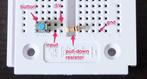
Figure 7-1. Simple switch on a breadboard
Building a circuit can take some time. On a breadboard, the more jumper wires and components you place, the more fragile a setup becomes. On the other hand, you don’t need tools and skills for soldering if you use a breadboard, and you can get basic components working quickly.
Let’s look at some other options for exploring circuits.
Grove Kit
For building circuits with a “plug and play” experience, the Grove Kits from Seeed Studio provide an interesting entry point (see Figure 7-2).
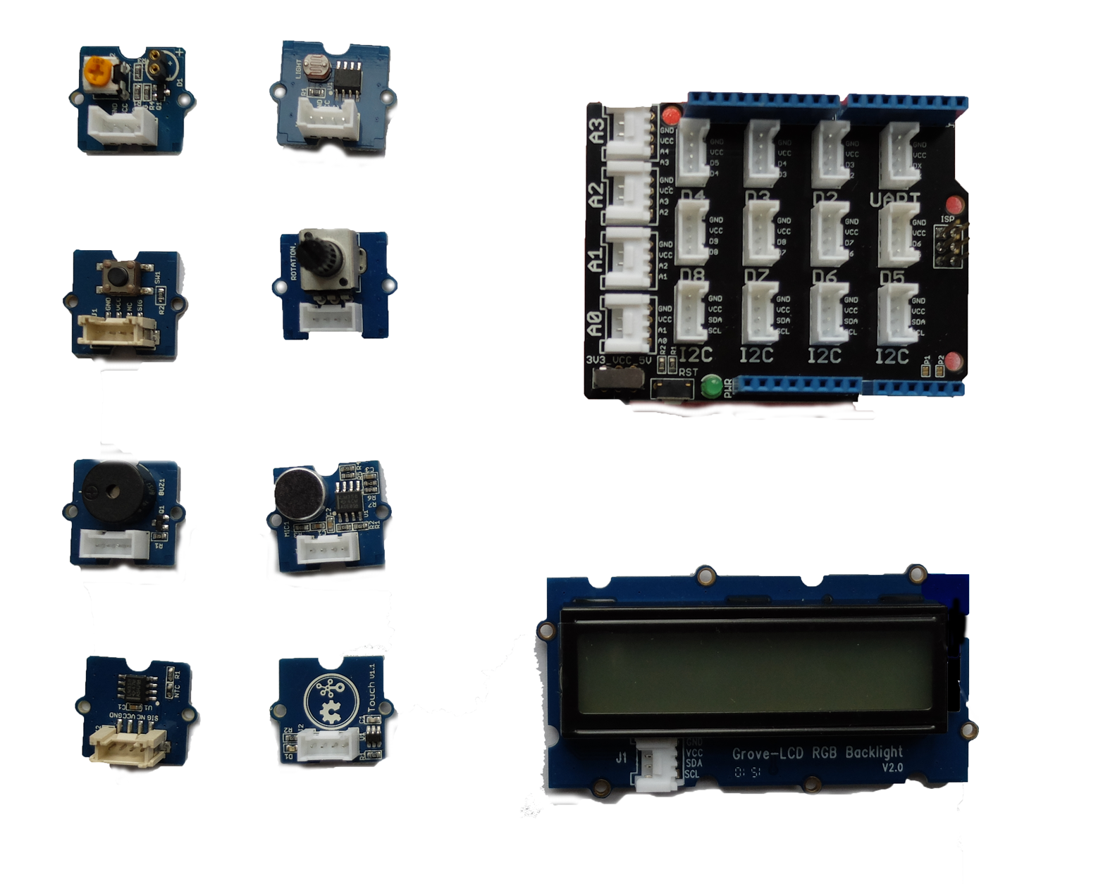
Figure 7-2. The Grove base shield (top right) provides headers to easily connect components (left and bottom)
The Grove kit is based on three ideas:
-
A simple “base shield” in an Arduino form factor provides standard headers for cables
-
Cables from components can then easily be plugged into the base shield
-
Components such as a button, a potentiometer, some sensors, a buzzer, and a display with the same standard header connectors as the base shield
Compared with a breadboard, you’ll easily have access to a button or potentiometer, for example. Instead of wiring up a button with a pull-up resistor as before, you’ll now have a button component as shown in Figure 7-3.
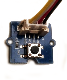
Figure 7-3. A simple button from the Grove Starter Kit
You can solder Grove headers to your own boards too. Some boards, such as the BeagleBone Green, have Grove headers mounted by default already.
Besides the Arduino form factor, the Grove headers make customs setups a bit harder to design. For example, when you need multiple buttons or potentiometers, it is better to design and solder your own boards. But for many software developers, the Grove system is a good start to explore electronics for embedded software development.
Soldering
It can be fun to learn soldering and build components yourself. Components that arrive unsoldered to a breakout can be cheaper, and you have some more flexbility to make components as you need them. Additionally, for debugging a setup, learning to solder can be important. For example, an LED soldered to a resistor, such as the one in Figure 7-4, can often be helpful to quickly check the voltage on a pin.
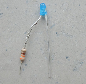
Figure 7-4. An LED with resistor for debugging
Note
Because LEDs, resistors, potentiometers, and switches are used frequently, it is a good idea to purchase a number of them. You can make them easily pluggable or breadboardable by soldering jumper wires onto them.
Similarly, you can turn a potentiometer into a debugging tool by soldering jumper wires onto it. A potentiometer typically has three pins: GND, full scale, and a divided voltage. When working on a sensor device, this last pin is one you want to attach to an analog pin of a microcontroller. When you adjust the potentiometer, the divided voltage moves up or down an analog scale from ground (0V) to the full-scale voltage.
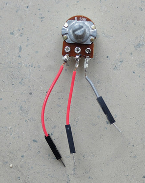
Figure 7-5. A potentiometer with jumper wires soldered onto it
Printed Circuit Boards
Soldering circuits with wires yourself quickly becomes time consuming for larger circuits. In these situations, a good option is to move to printed circuit boards (PCBs).
Many vendors such as SparkFun or Adafruit offer PCBs including a schematic of the board and the board layout including the used parts. Besides companies that promote open source hardware, a good place to find PCBs is at OSHpark, Tindie, or GitHub.
With computer programs such as Eagle or Kicad, you can easily adapt PCBs to your own needs. This is a two-phase process. First, you capture a circuit in a schematic editor. Then you turn the schematic into a layout that can be manufactured. For boards with two layers, you can order boards for less than $10 at places like OSHpark or DirtyPCBs.
While learning PCB design takes some time, it will save time later when you start building more complicated hardware devices. This can already be seen from the number of wires on a simple breakout board with LEDs, as shown in Figure 7-6.
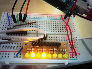
Figure 7-6. LEDs on a breakout board on a breadboard (you can find a simple PCB doing the same thing at https://oshpark.com/shared_projects/ZsQu0dA9)
For prototyping, breakout boards with small circuits to accompany components are especially useful. Breakout boards make components easier to access and often provide some basic configuration for components. Breakout boards not only work with “simple” components, but also with advanced components such as microprocessors and microcontrollers. For example, to turn the small pins of an Intel Edison into something useful for prototyping, a number of interesting boards, such as the ones pictured in Figure 7-7, can be used. The boards shown here were purchased from SparkFun.
For some boards, such as the Arduino Uno or a BeagleBone, there exist special boards that you can plug onto the “motherboard.” This idea of an Arduino shield is nicely explained at the Arduino website:
Shields are boards that can be plugged on top of the Arduino PCB extending its capabilities. The different shields follow the same philosophy as the original toolkit: they are easy to mount, and cheap to produce.
These shields (or “capes” for BeagleBone) can be very interesting for prototyping. If you want to focus purely on software development, these boards allow you to avoid thinking about circuit design almost completely.
A nice example for an Arduino shield is shown in Figure 7-8. This Arduino Uno–compatible shield provides a number of components, such as a real-time clock, temperature sensor, and input buttons. The board was designed by Dan Hienzsch and was funded with a Kickstarter campaign.
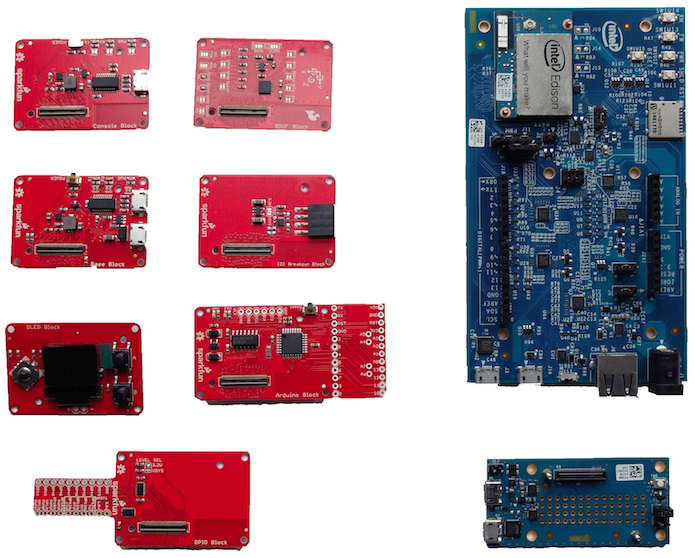
Figure 7-7. Some examples of breakout boards for the Intel Edison from SparkFun (in red)
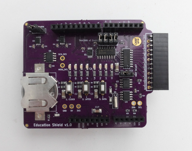
Figure 7-8. The I2C education shield
Tessel Modules
The capabilities of a Tessel can be extended via “modules.” On the Tessel 2, there are two module headers that provide pins to communicate with external devices. With modules, you can add the circuits and components needed to control motors or sensors. You can also build your own modules—for example, with help of Eagle or Kicad software packages. Figure 7-9, shows a simple diagram of an Eagle device for the Tessel module format.
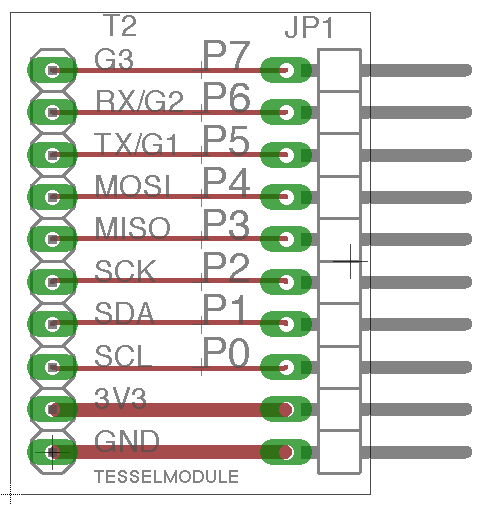
Figure 7-9. A simple Tessel module design for Eagle (https://github.com/embeddednodejs/tessellib)
Different Tessel modules will be shown in later chapters. For now, you can observe that the ports of a Tessel are meant to easily control external components. The module header pins can communicate with sensors or actuators, for example.
Basic Components
Now that you know about different ways to connect circuits and multiple components, let’s look closer at particular types of components. Components can be “passive” or “active.”
Passive components are somewhat similar to mechanical parts like heatsinks, which mainly dissipate energy. Passive components such as resistors or potentiometers are often useful to generate reference voltages. In contrast, active components are used to power lights, sound, or motion.
Many components need some kind of driver software. In embedded projects with Node.js, you’ll find many drivers for components at http://npmjs.com.
Still more concepts surrounding components influence the practice of writing software for hardware. We will review these additional concepts in the next section.
Datasheets
Electronic components are documented in datasheets. Typically, datasheets discuss the limits and constraints of device operation.
Most datasheets can be found online today. There are special search engines for datasheets, such as Parts.io. Companies like SparkFun or Adafruit can help you to translate abstract datasheets into easy-to-understand information for components that they sell.
Key information you will find in a datasheet includes:
- Operational voltage
-
To protect your boards and other parts, it is often important to identify the operational voltage of components. For example, a Raspberry Pi works on 3.3V, and connecting a 5V pin of an Arduino might do some harm.
- Communication with a part, such as what protocol it uses
-
Simpler parts might output a digital signal or analog voltage. Others might specify PWM. On parts with their own microcontrollers, the datasheet will have details on the part’s use of communication protocols such as I2C or SPI.
- Symbols and footprint
-
Schematics and footprints show how the various pins (e.g., the power and communication pins) need to be connected in order to function.
Passive Components
Many “passive” components are needed to adjust voltages or signal shapes. One simple passive component is the simple ceramic resistor, a physically static component made of ceramic and wire. In more advanced forms, passive components come as switches and potentiometers.
Potentiometers are often used to tune a voltage to a certain level. For example, a potentiometer can be used to adjust the volume of sound or the brightness of an LCD display. Another good use of a potentiometer is as an easy way to “simulate” a sensor. Sensors often output varying voltages. Turning the knob of a potentiometer that is connected to an analog pin often has a similar effect, but is easier to set up than the environment a sensor requires.
Besides providing voltage references, resistors and potentiometers also can protect active components such as an LED against high currents.
As shown in Figure 7-10, SparkFun provides a nice collection of passive and electromechanical components in the form of device libraries. A device library helps to organize components in a PCB project. The device libraries from SparkFun provide many useful prebuilt components. This includes electromechanical devices, such as tactile switches and trimming potentiometers.
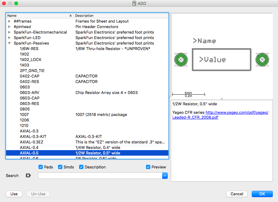
Figure 7-10. Eagle device library with passive components from SparkFun
LEDs
LEDs are simple “active” components because they convert electrical energy into light energy. In their earliest days, LEDs were used as simple outputs in displays, as shown in the Altair 8800 computer (Figure 7-11).
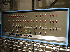
Figure 7-11. The Altair 8800 uses LEDs as a simple user display (source: https://flic.kr/p/5XrzTu)
In many embedded projects, LEDs are helpful to determine whether a device carries current or not. The LED datasheet shows two pins of an LED. The longer one (anode) is used for the positive voltage, while the shorter one (cathode) is used for the negative voltage. If the voltage difference between anode and cathode is above a certain level, the LED will emit light.
Different colors for LEDs usually have different operational voltages. This “forward voltage” at a certain operating current influences how brightly the LED shines. Depending on the operational voltage of your system, you can again calculate if and how much resistance you must apply to protect the LED.
Working with LEDs has many advantages: they are an easy way to visualize the working of a circuit and to check working software. You just have to apply a forward voltage and the LED will light up.
With a time-varying PWM signal, you also can modulate the brightness of an LED.
Sensors
Many embedded devices require inputs of some form. For example, in a weather station, you measure a physical property of the environment like temperature or humidity. This is done with sensors.
Data from sensors can be used to monitor and track processes, or to change an output of a device. The operation of a sensor is often visualized with a simple block, as shown in Figure 7-12.
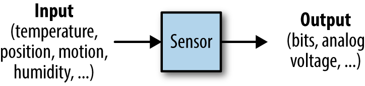
Figure 7-12. Voltages from a sensor measurement
Many different forms of sensors exist. One of the simplest examples is the temperature sensor. For devices that move, you can capture data about motion with gyroscopes or accelerometers. Also, measuring distance is easily possible with ultrasonic sound detectors.
Temperature
Measuring temperature is an easy start into physical computing. Temperature sensors also provide a nice “Hello, World!” experience when beginning with IoT development.
In Figure 7-13, you’ll see two popular choices for capturing temperature. On the left is an approach used by the Grove Kit from Seeed Studio, and on the right is a the DHT11 temperature and humidity sensor.
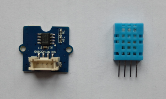
Figure 7-13. Two common forms for measuring temperature: a thermistor (left) and a DHT11 (right)
In the Grove Kit sensor, the temperature is mapped to a resistance. Combining this variable resistance with a known supply voltage, the temperature can be sampled with an analog input pin on a microcontroller. For Arduino users, you can find a sketch with a temperature sensor on the Seeed Studio Wiki page.
In the case of a DHT11, the temperature is measured and encoded as a digital string of zeros and ones. The temperature can then be read with a digital pin. This sensor is especially popular with Arduino and Raspberry Pi.
Temperature sensors come in different accuracies and integration levels. If you need high accuracy, the MCP9808 is a popular choice that can be purchased on eBay. Also, the Atmel AT30TS750A that comes with the I2C Eduction Shield (see Figure 7-8) is easy to use.
Motion
Detecting motion can often be useful for robotics applications. A nice foundation for these kinds of projects is given by accelerometers, gyroscopes, and magnetometers. These components are often combined; for example, the SparkFun “9 Degrees of Freedom Board” uses the LSM9DS0 9DOF inertial measurement unit (IMU), as shown in Figure 7-14.
Another option to explore motion with an embedded device is the MPU6050. You will find a number of interesting examples online showing how to connect an Arduino to this component.
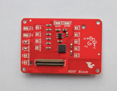
Figure 7-14. The IMU breakout board from SparkFun
Note
In the Embedded.fm podcast “Episode 9: Kidnapped and Blindfolded,” Elicia White provides a nice overview of how these sensors work (http://embedded.fm/episodes/2013/6/25/8-kidnapped-and-blindfolded).
Another good option to experiment with motion is by purchasing a Nintendo Wii Nunchuk controller (shown in Figure 7-15) and attaching a breakout board to it. The Nunchuk gives you an accelerometer and a gyroscope in the plus version.
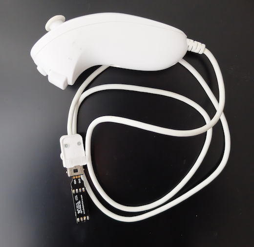
Figure 7-15. A Wii Nunchuk
Ultrasonic Distance
With ultrasonic distance sensors, you can easily add detection for obstacles to an embedded project. Several sensors exist but the SFR-10 is a popular one. The SFR-10 adds some filtering to the input signal and makes processing the signal easier.
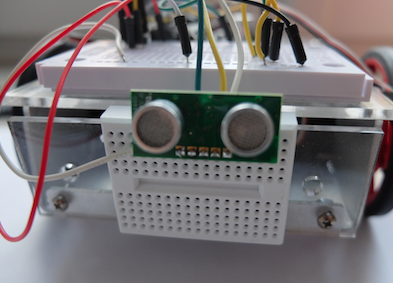
Figure 7-16. An SFR-10 mounted on a robot
Actuators
While sensors can capture data from physical phenomenon, actuators are used to drive motion or change things around you. A block diagram of an actuator is shown in Figure 7-17.
Speed or position of a motor are often controlled with “analog” output pins.
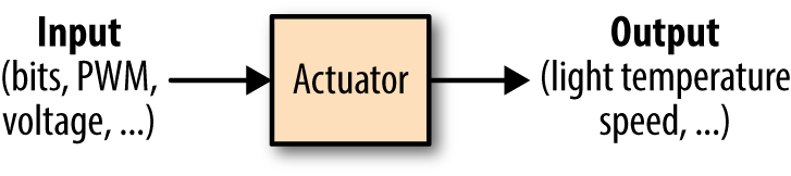
Figure 7-17. Voltage input to an actuator
The mapping from the “continuous” to the “discrete” world is done with ADCs, or “analog-to-digital” converters. The other direction is covered with DACs, “digital-to-analog” converters.
Servo Motors
Servo motors allow you to position something, such as pointers or steering wheels. They provide rotational motion in a limited range—imagine mapping a servo motor’s range as a dial from zero to 100.
“Continuous” servo motors, so called because they do not have a limited range, are popular to turn cogs or wheels. Instead of setting position, on a continuous servo motor you can set the speed within a range, such as to control the speed of a vehicle.
Figure 7-18 shows a small servo motor. A servo motor has a gear box, a DC motor, and a rotor to move something. It typically has three wires: GND, power, and a reference signal.
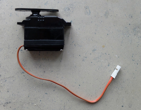
Figure 7-18. A standard servo motor with three wires (in a ribbon cable)
The servo motor is contolled by an electric signal which measures the position of the rotor and determines the amount of movement based on feedback coming from the microcontroller.
Stepper Motors
Stepper motors are similar to servo motors in that they can be used to position something. The motor can rotate in certain “steps.” A stepper motor is typically able to drive with more force than a servo motor, which is useful if you want to move something heavy. Stepper motors can be very precise.
DC Motors
DC motors leave much control to the engineer. Typically, they are used as power train for remote control vehicles. The speed of a motor is controlled by a voltage. The higher the voltage, the higher the current and the faster the motor rotates. However, building a feedback loop to accurately control speed or position with a DC motor is more difficult.
Multimedia
Special components are needed for multimedia applications, such as displays and cameras. Let’s quickly review some options in that space.
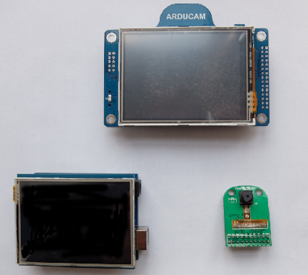
Figure 7-19. Outputs for multimedia
Displays come in many different technologies. For multimedia applications, LCD and TFT displays are especially interesting.
To drive many pixels on a display, you’ll often require a special processor or a more powerful processor than a simple Arduino will have.
On an embedded Linux system, you’ll need a display driver in the form of a framebuffer such as https://github.com/notro/fbtft.
Cables
To make a connection between devices for debugging, providing power, or simply controlling devices, it is often necessary to work with multiple cables. USB cables in particular are widely used.
USB Cables
Working with embedded devices, it is often a good idea to gather a number of USB cables with different plug types.
The USB Micro B type is slowly becoming a default for programming microcontroller boards. Yet, you’ll also encounter boards and setups where you require USB Mini or type A cables.
FTDI-USB-Cable
Most microcontroller boards have a serial port that can be used for debugging signals. Sometimes, direct access to the serial port of a processor is the only way to see output when debugging firmware.
To make working with serial ports for development easier, it is often a good idea to build or buy an adapter cable to use on a serial port.