Table of Contents for
Node.js for Embedded Systems
 Node.js for Embedded Systems
Published by
O'Reilly Media, Inc., 2016
Node.js for Embedded Systems
Published by
O'Reilly Media, Inc., 2016
- Cover
- nav
- Node.js for Embedded Systems
- Node.js for Embedded Systems
- Foreword
- Preface
- 1. Connecting Worlds
- 2. Blink with Arduino
- 3. Espruino
- 4. The Tessel 2
- 5. Particle Photon
- 6. Single-Board Computers
- 7. Components for Prototyping
- 8. Node.js Libraries for Hardware
- 9. Exploring Network Protocols
- 10. Web Frontends for Things
- 11. Entering the Cloud
- 12. Making Robots with Node.js
- 13. Wireless Data with Bluetooth
- 14. Toward the Physical Internet
- 15. From Products to Toolkits
- A. Node.js
- B. Early Hardware for IoT Systems
- Index
- About the Authors
- Colophon
Chapter 2. Blink with Arduino
When you learn a new programming language, the first exercise is usually to display “Hello, World!” on a screen. When working with a new embedded device, the equivalent first exercise is to blink a light, often an LED. By toggling an LED, you check that the main parts of a system are working and that you can control them. Arduinos are famous for letting users get LEDs to blink very easily. Because it’s easy to get up and running with Arduino, you’ll be able to quickly get a feel for where and why JavaScript can be used in an embedded system.
To begin, what does it take to toggle an LED on and off? From a hardware perspective, most boards with a microcontroller have LEDs for debugging built in. And from a JavaScript viewpoint, controlling the blink of an LED can be as simple as:
led.toggle();
However, to run this code, you need to set up the hardware. If you want to control an external LED, you must build a small electronic circuit. Depending on which board you use, you might need to configure a toolchain and connect a special device called a “programmer” to flash the board—JavaScript is the easy part.
Starting with an Arduino is very helpful in exploring the building blocks of a simple embedded device. For this, you must set up the pins of a microcontroller unit and build basic electronic circuits. Understanding the building blocks and their configurations can be challenging.
For this reason, we will begin with a discussion with Arduino. Broadly speaking, an Arduino is a board with a microcontroller. It’s not necessary to buy all of the boards we’ll cover, but it is important to understand these components on a basic level because the chips on a board define the behavior of the embedded system. Experiences with one chipset might apply to projects with other chips at a later stage.
Getting Started with Microcontrollers
Microcontroller units (MCUs) typically live in watches, pocket calculators, or small radios.
As shown in Figure 2-1, a microcontroller provides input and output pins to interact with a physical environment. Besides physical pins, a microcontroller can also run small programs to process events from pins with the help of its instruction set.
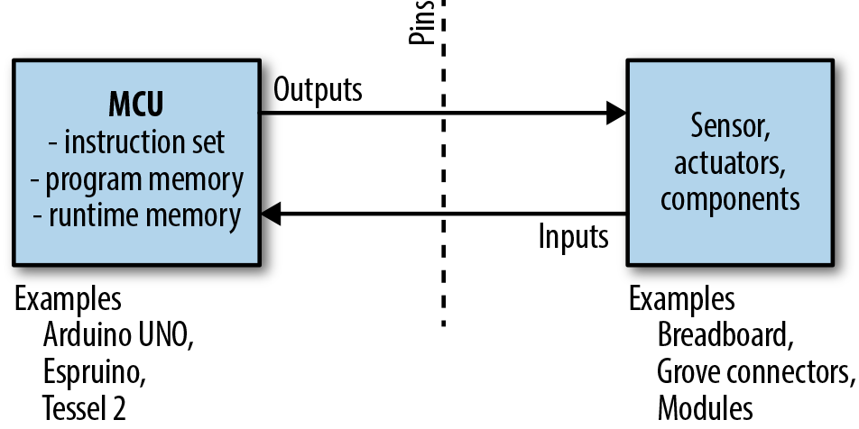
Figure 2-1. Microcontrollers provide pins and programming capabilites
An instruction set of a microcontroller only supports a number of operations, such as basic arithmetic operations or manipulation of the control flow in a program.
Because most programmers find it difficult to write programs with instructions in hex code, programs for a microcontroller are usually compiled from a higher-level language. The resulting binary is stored in the flash memory of the MCU, sometimes refered to as read-only memory (ROM). This memory is nonvolatile, meaning after power on and off, the content remains. The size of the flash memory is typically 32 KB for an Arduino.
In contrast, the “static RAM” (SRAM) of a microcontroller stores variables during program execution. The SRAM is volatile—that is, after you power off the device, the content is lost. SRAM is also smaller than flash memory, typically 1–2 KB for an Arduino.
MCUs can only run tiny programs, but because of this trade-off, they consume only a few milliamperes of current (between 10–20 mA for an average Arduino) during operation. This makes MCUs a good fit when building devices that must run on a battery.
As we will discuss later in this chapter, microcontrollers are also interesting because you must capture signals from pins in “real time.” For now, it is only important to remember that a microcontroller has more building blocks than a central processing unit (CPU).
If you begin searching around online for microcontroller starter kits, you’ll quickly discover a wide variety of products with many different chips. In particular, Arduino, Espruino, and Tessel 2 have succeeded in making microcontrollers accessible to a wide audience. We’ll discuss Espruino and Tessel 2 in Chapters 3 and 4, respectively. But first, let’s take a look at Arduino.
Arduino
If you want to explore electronics and hardware, one category of boards is especially popular: Arduino boards.
Arduino is a pioneer of open source hardware.1 This means you can find schematics and board layouts on the Internet to help you configure your own embedded devices. For example, Figure 2-2 shows the board layout of the Arduino Uno.
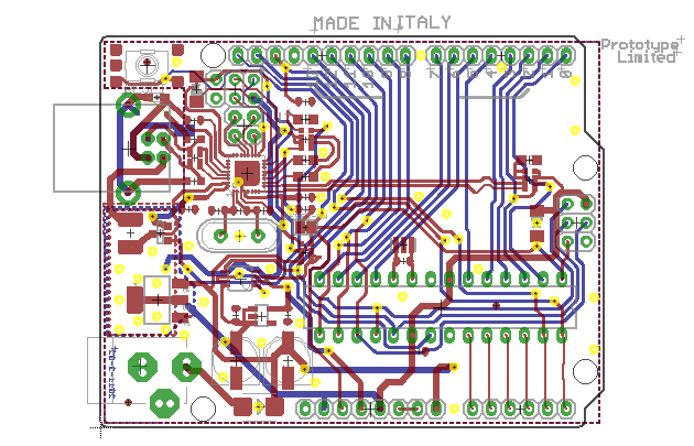
Figure 2-2. Most Arduino boards are open source hardware (source: https://www.arduino.cc/en/main/arduinoBoardUno)
Besides the Arduino Uno, there are many other types of Arduino boards, such as Arduino Nano, Leonardo, Micro, and Mega. Most Arduino boards have an ATmega328 microcontroller from Atmel. The ATmega328 has an 8-bit instruction set, 32 KB of flash memory, and 1–2 KB of RAM. Compared to most modern computers, this is not much.
Note
If you find these numbers confusing, you can get an idea of the performance differences through the following metaphor: a microcontroller is like a small animal—a swift cat, for example. Compare this cat to an elephant, which can carry a lot of weight, but needs many more resources to survive. Your computer (a processor) is an elephant compared to a microcontroller. Both animals have useful features.
While you can buy Arduino boards for around $20, you can also find Arduino clones from China for a couple bucks. With cheap boards, you will sometimes need workarounds such as special drivers for the serial port.
An example of an Arduino is shown in Figure 2-3. The board is connected to a Grove header shield and a push button. Grove headers and connectors are the white connectors to mount components (as will be discussed in Chapter 7). The Arduino Nano is a nice board to have, because besides being cheap, it has a very small form factor (hence its name).
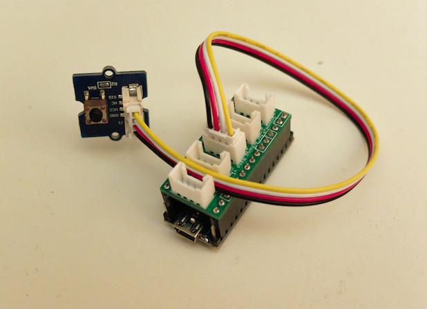
Figure 2-3. Arduino Nano with Grove headers and push button
You’ll need to consider the purpose and scope of your project before deciding which Arduino boards to work with—each board has special features that you’ll want to consider as you explore electronics and hardware. Note that the form factor of an Arduino Uno board has become very popular. Peripheral devices and circuits can be directly plugged into the board with Arduino-compatible shields, which makes Arduino modular. Similar to combining code libraries, you can reuse the hardware shields on top of an Arduino.
Besides a board, you’ll need some components to work with. For example, Figure 2-3 shows an Arduino Nano with a push button. This example uses a “shield” with Grove headers where you can connect components. Shields and components will be discussed in Chapter 7.
Because most Arduinos only have 32 KB of flash memory, the space for a JavaScript runtime environment is rather limited. Memory in general puts hard constraints on efficiency and code size on a microcontroller. For this reason, many programmers choose a hybrid approach of using JavaScript outside of and C inside of an embedded device.
Note
The Arduino IDE removes a lot of obstacles that make embedded development hard. But beware: many programmers will advise you to learn C and C++ at some point. In comparison to JavaScript, C programming offers more control over a machine. However, it takes time to learn about the compilers, linkers, and operating systems that go along with C programming. We advise you to use JavaScript first. If you then want to go beyond programming embedded systems with JavaScript, Making Embedded Systems by Elecia White (O’Reilly, 2011) is a good start.
The Blink Sketch
To blink an LED, you have to run a “sketch” on the Arduino. An Arduino sketch hides a lot of the complexity from a microcontroller. The Arduino IDE comes with a number of sketch examples to learn embedded development. Writing, building, and uploading a Blink sketch will give you a first feeling of how microcontrollers work.
If you create a new Arduino sketch, you’ll see the following basic code structure:
voidsetup(){}voidloop(){}
These two functions are the foundation of every Arduino program. The setup() function is where you put code to configure the hardware and initialize variables. This function will only run once when your Arduino is turned on. The loop() function is where the the “main” program goes. We’ll see shortly how this looks for a blinking LED. Note that most Arduino boards have an LED connected to pin 13, which you can easily toggle for testing.
The separation of code into setup() and main loop() is common in the embedded world. First, you’ll have a function to configure your microcontroller and peripherals. Then follows an infinite loop, where different instructions are executed. The code in the infinite loop is repeated as long as the device has power. To make an LED blink with an Arduino forever, you would use the following:
voidsetup(){// initialize the digital pin as an output.pinMode(13,OUTPUT);}voidloop(){digitalWrite(13,HIGH);// turn LED ondelay(1000);// wait for a seconddigitalWrite(13,LOW);// toggle LEDdelay(400);// wait 400 ms}
While keywords such as void are part of C, Arduino programs contain more keyword-like commands such as pinMode, delay, and digitalWrite as just shown. These commands are part of a hardware abstraction layer (or HAL) Arduino provides to hide the lower-level complexities of a microcontroller. No matter which Arduino board you use, these statements are properly translated to pin configurations. By the way, pinMode configures the mode of a pin (i.e., if it is an input or output). If a pin is configured as output, you can write state with digitalWrite. If the pin is an input, you can read state with digitalRead.
Note the name of the instructions to change the state of pins. The Arduino nomenclature has made its way into some JavaScript libraries, as you will see shortly. Before examining how, let’s see the Arduino example in action.
A look at the Arduino IDE (shown in Figure 2-4) quickly reveals two functions: a “verify” button that compiles C and C++ to byte sequences that a microcontroller can run and an “upload” button that places your code in the free program memory of a microcontroller (ROM).
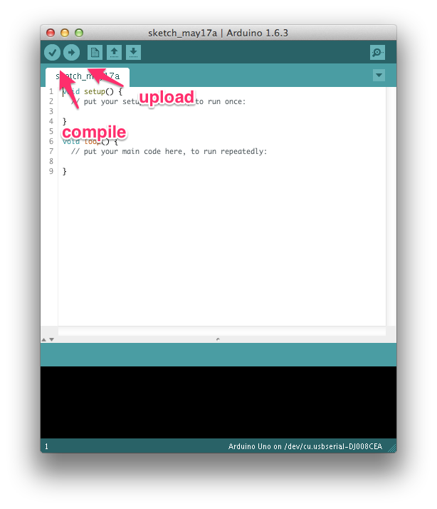
Figure 2-4. The Arduino IDE
If you have an Arduino and press the compile button, in the console you will see:
Sketch uses 1,030 bytes (3%) of program storage space. Maximum is 30,720 bytes.
Global variables use 9 bytes (0%) of dynamic memory, leaving 2,039 bytes for
  local variables. Maximum is 2,048 bytes.
This shows how compact the code is. The code will use only 1 KB of flash memory. And, only 9 bytes of RAM are necessary!
Next, you can press the upload button. After a brief wait while the device is flashed, you will see LED 13 blinking, as shown in Figure 2-5.
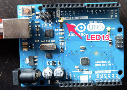
Figure 2-5. The default LED to blink on the Arduino Uno
Similarly, you could explore using input pins or different forms of output signals. We’ll discuss more features of microcontrollers later. Let’s first look at controlling an Arduino with JavaScript.
The Firmata Bridge
While Arduino sketches (or more specifically, custom firmware development) give you compact code, it can be easier to share, explore, and manage libraries for embedded devices with JavaScript.
To use an Arduino with JavaScript (and Ruby, Python, and other scripting languages), Arduino provides standard firmware that makes pins accessible via serial communication. Basically, Firmata turns a microcontroller into a “client” that follows commands from a “host” computer.
Firmata is an open protocol similar to the MIDI protocol used to compose music for different devices. Like the MIDI protocol, the Firmata protocol can be used to talk with many different embedded devices.
Arduino provides Firmata as a sketch. You can flash Firmata within the Arduino IDE to an Arduino by navigating to Examples → Firmata → StandardFirmata. Once you have the Firmata code running on the Arduino, you can start using all kinds of client software on your host computer.
To test that flashing Firmata was successful, you have several options. First, on the Firmata website, you will find a number of Firmata clients. The Firmata Test Program is a popular debugging tool. Figure 2-6 shows the UI.
Second, you can interact with Firmata from a web browser with browser plugins. If you want to try, you can download the Google Chrome Firmata plugin. It will give you a similar user interface as the standalone Firmata test application.
The Firmata protocol is also a popular choice to get started with Node.js and embedded systems. By using Firmata, you can do a lot of computing on a host computer. The control of a microcontroller from outside is also the disadvantage of using Firmata: you’ll need to have a host computer connected to your microcontroller in order to have it doing something useful.
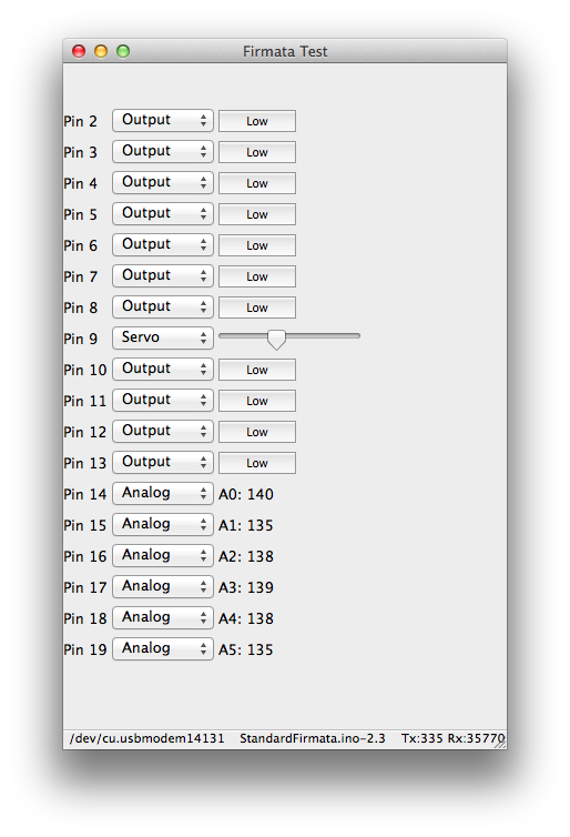
Figure 2-6. The Firmata test program offers a way to test the pin functions of a microcontroller
Programming an Arduino with JavaScript
Once you have checked your connection to an Arduino with a Firmata test client, you can bind a JavaScript process to your board.
To talk with Firmata from JavaScript, you can use the Firmata library, originally written by Julian Gautier and currently maintained by Rick Waldron.
In a new project, you can start with:
$ npm init --y
$ npm install --save firmata
With this library, we can connect to input and output pins.
Let’s look at a blinking LED again:
// blink_led.js// the Firmata protocol provides a simple protocol to an embedded systemvarBoard=require('firmata');Board.requestPort(function(error,port){if(error){console.log(error);return;}varboard=newBoard(port.comName);// start to blink when the Arduino is readyboard.on("ready",function(){// main partconsole.log('connected: '+modem);varledOn=true;// configure pin 13 as outputboard.pinMode(13,board.MODES.OUTPUT);// blink the LEDsetInterval(function(){if(ledOn){console.log('ON');board.digitalWrite(13,board.HIGH);}else{console.log('OFF');board.digitalWrite(13,board.LOW);}ledOn=!ledOn;},500);});
To blink the LED, run the preceding script with Node.js:
$ node blink_led
If everything worked, you should see the LED turning on and off. This is also a good moment to compare the differences in code expressed in terms of Arduino and JavaScript.
In the JavaScript example, you get a board object, where you can listen to events from the hardware. For the blink example, you first wait until the board emits the “ready” event (the connection works properly). Once this happens, you can change the state of the board with functions using digitalWrite and pinMode. You could easily interact with the JavaScript board object in a web server or web interface too (we’ll discuss how to do this in Chapters 9 and 10).
Functional Blocks of an MCU
Now that we’ve looked at some examples of how to blink an LED, think about this for a second: the LED is connected to a pin of a microcontroller. The pin acts as the interface from the program code to some concrete electrical signal. Pins can be grouped by functional blocks—for example, inputs or outputs or pins for communication. Inside a microcontroller, pins can be attached to timers to work with signals in real time. Understanding the role of pins can be difficult; to aid your understanding, it’s often beneficial to consult pinout diagrams (which we’ll discuss later in this section).
Pins
Pins of an MCU come in two categories: inputs and outputs. A pin can either “drive” signals to peripherals and components, or it can “detect” changes from the outside.
Inputs and outputs are technically quite different. While inputs are all about capturing the state of signals, outputs can drive current into components. Because Arduino boards are capable of driving several milliamperes of current, they’re a good fit for controlling small actuators such as motors or lights.
Besides acting as “force” (output pin) or “sink” (input pin), pins carry analog or digital signal types (see the following sidebar for details on how this works).
When writing embedded software, the first step is to locate and configure the pins of the microcontroller. For example, an Arduino Uno has 5 analog inputs and 13 digital pins known as general-purpose input/outputs (GPIOs). Of these 13 GPIOs, 5 pins can emulate an analog output with the help of pulse-width modulation (PWM), as will be discussed in “Pulse-Width Modulation”.
On an Arduino, you first configure the direction of a pin. To read data from it with software, you must configure the pin as input. With Arduino and Firmata, if you want GPIO pin 12 to be an input, you would configure it as follows:
board.pinMode(12,board.MODES.INPUT);
Or, to write data to another device, you can configure another pin as output:
board.pinMode(12,board.MODES.OUTPUT);
On an Arduino, toggling a digital pin to a high voltage is done with:
board.digitalWrite(13,board.HIGH);
To write a low voltage, you would write:
board.digitalWrite(13,board.LOW);
Besides simple inputs and outputs, port pins often provide more functions. This means you not only can read a digital state, or write it, you can also start up special forms of communication, such as PWM and hardware communication protocols.
When different resources on a chip use the same port pins, we are referring to “multiplexing” pin functions. The way this works is defined by the chip architecture of a microcontroller defines how multiplexing works. Let’s dig into the building blocks of a microcontroller starting with its CPU.
Microcontroller Versus Microprocessor
On top of providing pins for building circuits, microcontrollers can run programs with the help of a CPU. The datasheets for a microcontroller provide all the details, and the following specs are of particular interest:
-
The amount of memory (volatile and nonvolatile) to store variables and code
-
The type of instruction set to execute code and operations with variables
-
The timers to change pin states with high timing accuracy
-
The power consumption at a certain operating frequency
Compared to the CPU of a bigger computer, these parameters make a microcontroller nice for embedded systems on a battery. Moreover, the costs of microcontrollers can be significantly lower than those of microprocessors (though microprocessors are becoming cheaper due to high volume demands).
However, microcontrollers also have disadvantages. In particular, their performance for computations can be a problem. If you want to connect a microcontroller to a network, or if you want to run a web server or database, this is where microprocessors become very interesting.
Microprocessors (MPUs) have many more pins, more memory, and much more power for computations. The boundaries between MCU and MPU are not always clear, but you will usually have to deal with some tradeoffs when chosing a board with a microcontroller or microprocessor.
Note
The choice between MCU or MPU can be difficult. Many suppliers provide white papers to make it easier to understand what your application requires. For example, Atmel’s paper “Microprocessor (MPU) or Microcontroller (MCU)?” provides some additional insight.
In earlier code examples, we worked with a number of functional blocks of a microcontroller. As you can see from the block diagram, Arduino provides several hardware abstractions.
Let’s look a bit deeper into the structures and functions of the main building blocks of an Arduino Uno: the Atmel ATmega328 microcontroller.
Block Diagrams
To understand how the software in the microcontroller blinks the LED, let’s look at the block diagram of the ATmega328 microcontroller, shown in Figure 2-8. In general, understanding functional block diagrams is important when developing software for embedded devices.
The block diagram in Figure 2-8 shows the typical building blocks of a microcontroller. The CPU of the ATmega328 has an 8-bit instruction set. Instruction sets provide operations around which programmers build programming languages and compilers.
The code and data are stored in different forms of memory. In Figure 2-8, the memory is shown in the upper-right part. “Flash” generally means slow, nonvolatile memory, and SRAM means fast but volatile memory. You generally store programs in flash, while the RAM at runtime of a program is stored in SRAM.
Besides these building blocks, what is interesting from a software perspective are the interfaces of the microcontroller. These are all the arrows that come out and go in on the bottom and left—for example, the ports.
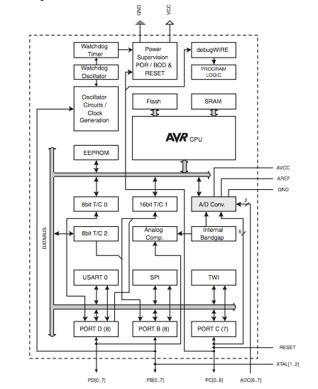
Figure 2-8. A functional block diagram of the datasheet from the ATmega 328 microcontroller
With GPIOs, it is possible to read and write data. From the block diagram, you can see that an Atmel MCU has GPIOs that are organized in three ports: Port B, Port C, and Port D (seen near the bottom of Figure 2-8).
So-called “peripherals” are also important for communication and sensing the outside world. Some peripherals act as input and output ports. Timers can measure the time between stop and start events. And, analog-to-digital converters can convert continuous analog signals into bits and bytes for digital processing.
The ATmega328 Atmel chip multiplexes the following blocks to the ports:
- Port D provides USART and UART
-
Many embedded devices must transfer data from one side to another. One kind of serial data transfer uses a Universal Synchronous Asynchronous Receiver/Transmitter (USART). This peripheral function drives data bits from a sender to a receiver via two wires and an extra clock line. One variation on USART is called UART (Universal Asynchronous Receiver/Transmitter). In this form, a clock can be generated on the devices, and there is no need for an extra clock line. We’ll discuss serial communication in several places throughout the book.
- Port B provides SPI communication
-
Serial peripheral interface (SPI) is another approach to communicating between devices. SPI connects devices in a “master” and “slave” fashion.2 This means one device controls the communication flow. This kind of communication is a relatively fast form of serial communication. The SPI protocol requires four signals for communication. Since it always uses a clock line, the communication happens synchronous.
- Port C provides TWI
-
The ATmega328 includes another form of serial communication called a two-wire interface (TWI). It is more commonly known as I2C (“i squared c”) and is popular for slow communication with sensors or displays. I2C uses one line for a clock signal, which means that I2C communication also happens synchronous.
Most communication modes are directly supported by JavaScript libraries. Serial communication is very common for many use cases. A JavaScript library for serial communication will be discussed in Chapter 8. Let’s continue with pins that are important to sense the physical world around us.
Analog Inputs
Looking at the building blocks in Figure 2-8, we can see a rectangle “A/D conversion.” Not all pins on the Arduino support reading analog values, only pins A0 to A5. The analog input block provides a number of “channels” to measure the physical environment with sensors.
In the Arduino language, these pins read a variable (“analog”) voltage and report that value as a 10-bit number representing 0–5V. An analog value has a “continuous” value in a range, so it does not represent a state. The range is represented by a resolution with bits—for example, a 10-bit A/D converter has 210 different values, or 1024 values (in hex values the range would be 0x00–0x3ff).
The simplest approach to understanding what happens when reading an analog input is with a potentiometer.
Note
Potentiometers are often used to adjust voltages, sound, or brightness, for example. They consist of a knob or a slider that you can adjust, which allows you to play with an analog voltage. You’ll learn more about using electrical components in Chapter 7. But if you are confused right now, Practical Electronics by J. M. Hughes (O’Reilly, 2015) is a good resource for learning more about the basics of electronics.
If you connect a potentiometer to analog input A0 as shown in Figure 2-9, you can read the analog voltage on the input pin with:
board.analogRead(0,function(data){console.log(data);});
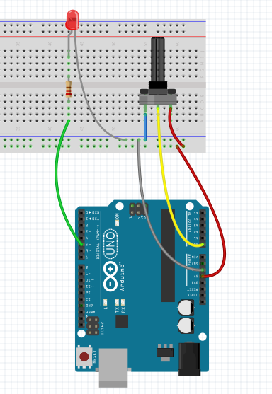
Figure 2-9. Potentiometer connected to analog input A0
You could influence the delay of the blinking LED on an Arduino as follows:
// analog_read.js// load firmata dependencyvarBoard=require('firmata');// pin definitionsconstLED=5;constPOT=0;// init variablesvarledOn=0;// whether LED is ON or OFFvardelay=0;// blink delay// make connectionBoard.requestPort(function(error,port){if(error){console.log(error);return;}varboard=newBoard(port.comName);// wait for connectionboard.on("ready",function(){functionblink(){board.digitalWrite(LED,ledOn);ledOn=!ledOn;setTimeout(blink,delay);}// update variableboard.analogRead(0,function(d){delay=d;});blink();});});
Often, you need to scale the input range of a sensor, or as in this example, the potentiometer (POT). In this case, the value from the analog pins returns a value between 0 an 1023. This values affects the delay for blinking.
When the blink delay is below 100 ms, the human eye cannot perceive the blink of the LED anymore. To map the blink delay to a range that can be seen by the human eye, you use a “map” function. The function from Arduino map can be rewritten in JavaScript as follows:
functionmap(x,in_min,in_max,out_min,out_max){return(x-in_min)*(out_max-out_min)/(in_max-in_min)+out_min;}// e.g. map(value, 0, 1023, 400, 1600) --> maps a value in a range from 400 to 1600
Now, the full variable blink example reads:
// map_example.jsvarBoard=require('firmata');// pin definitionsconstLED=5;constPOT=0;// init variablesvarledOn=0;// whether LED is ON or OFFvardelay=0;// blink delayfunctionmap(x,in_min,in_max,out_min,out_max){return(x-in_min)*(out_max-out_min)/(in_max-in_min)+out_min;}// make connectionBoard.requestPort(function(error,port){if(error){console.log(error);return;}varboard=newBoard(port.comName);// wait for connectionboard.on("ready",function(){functionblink(){board.digitalWrite(LED,ledOn);ledOn=!ledOn;setTimeout(blink,delay);}// update variableboard.analogRead(0,function(d){delay=map(d,0,1023,400,1600);});blink();});});
If you turn the knob of the potentiometer to the left, you get a minimum blink delay of 400 ms. If you turn the knob to the right, the delay will be 1.6 s.
Pulse-Width Modulation
In many projects, you not only have the requirement to sense the environment, you will also need to change the environment. This is what actuators are about. An actuator can be a motor, a loudspeaker, or again, the blink of an LED.
Actuators respond to signals with different forms. Pulses with different widths are especially common. This modulation scheme is called pulse-width modulation (PWM). As you can see in Figure 2-10, you specify the percentage of the time that the signal is high, also known as the “duty cycle.” This results in an often uneven square wave, as the pin approximates a percentage of the full signal by quickly toggling how long the signal is on versus off within a short period.
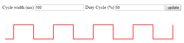
Figure 2-10. Pulse-width modulation; play with it here http://embeddednodejs.com/pwm
To generate PWM signals, a microcontroller often can often reuse exisiting blocks, such as GPIO and internal timers on the chips.
The mechanism behind PWM is as follows: an internal timer on the MCU sets the state of a pin to HIGH for a certain time, and LOW for the rest of a cycle. On average, the output is an analog voltage between ground and the supply voltage. This approximates an analog value and works fine for slow actuators. If you want fast-changing analog signals, such as needed for good quality audio, you’ll need to explore the use of digital-to-analog converters (DACs). Unfortunately, simple Arduinos don’t have DACs onboard.
Let’s now get some practice using PWM to fade an LED. The Arduino example “fade” can be translated to JavaScript as follows:
// analog_write.jsvarBoard=require('firmata');// led pinconstLED=5;varbrightness=0;varfadeAmount=5;Board.requestPort(function(error,port){if(error){console.log(error);return;}varboard=newBoard(port.comName);board.on("ready",function(){// configure pin as PWMboard.pinMode(LED,board.MODES.PWM);// fade the LED every 30 msfunctionfadeLed(){brightness+=fadeAmount;if(brightness==0||brightness==255){fadeAmount=-fadeAmount;}board.analogWrite(LED,brightness);setTimeout(fadeLed,30);}fadeLed();});});
A small warning: not every digital pin has access to a timer/counter. So, not every pin is able to drive a PWM output. On an Arduino, there are usually six pins with PWM functionality. These pins are commonly marked with a tilde.
Pinouts
Because reading functions of pins in datasheets is a time-intensive process, so-called pinout diagrams—like the one shown in Figure 2-11—help visualize pin functions.
While datasheets provide many details of what is going inside a chip, software developers are mostly interested in the interfaces of chips. To make writing embedded software easier, pinouts are a handy way to look up the names or locations of pins.
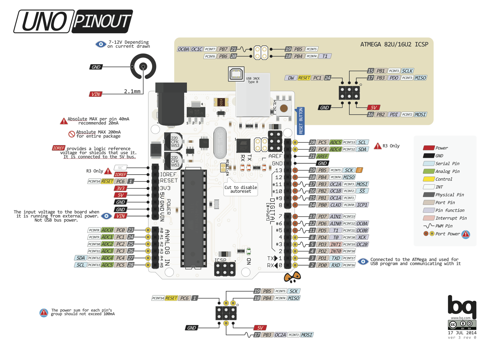
Figure 2-11. An Arduino Uno pinout that shows the location and functions of pins (http://www.pighixxx.com/test/pinouts/boards/uno.pdf)
From this pinout, we quickly get an overview of the different pin functions. In addition to the pin mapping that Arduino libraries use, you’ll see the name of the lower-level name and function from the datasheet. For example:
Arduino Pin 9 | Physical Pin 15 | Port B | Output/Compare/Timer 1
For beginners of embedded development, consulting a pinout can be simpler than reading dense datasheets. Later, when you get more familiar with a microcontroller, you can explore the alternative functions of pins in a pinout or datasheet.
PighiXXX provides pinout diagrams for a number of popular Arduino boards.
Firmware
Software inside an embedded device is also called firmware. After firmware is built and uploaded, a microcontroller knows what to do.
When using JavaScript for embedded devices, we often can simplify our lives by skipping custom firmware in C or C++. But a lot of software for hardware is written in C. It can be helpful to understand how custom firmware development works.
Firmware is stored in the “nonvolatile memory” (NVM) of a microcontroller, sometimes referred to as ROM. Changing programs in NVM is commonly called “flashing” a device. Flashing a device often requires a special programming device or a “programmer.” To make programming devices easier, many boards support at least some flashing of NVM via USB.
The NVM can be organized into different address spaces. A small address space is reserved for the bootloader of a microcontroller. Similar to the BIOS inside a desktop computer, a small part in NVM is reserved for booting the device. This part of firmware is also called the “bootloader” and is independent from an application or “user code.” In the case of Arduino, the bootloader starts up the Arduino and checks for programming requests from the outside.
Note
For security reasons, flashing a bootloader via USB is often not possible. As long as your embedded code on an Arduino does not hit the wall of 32 KB, tinkering with the bootloader is often not required either.
Developing firmware is often highly dependent on which microcontroller you use. First, you need to choose the appropriate tools and compilers. Compiling a program for an AVR-compatible microcontroller is different from programming an ARM device or an x86. Then, writing compiled programs into the flash memory often requires special “programming tools.” The tool that does this for Arduino is called avr-dude. A popular tool for ARM-based microcontrollers is openocd.
To use JavaScript with embedded devices, you usually build some kind of bridge layer, such as the Firmata protocol or Tessel 2 firmware. Alternatively, you can build your own bridge with JavaScript to an embedded device based on serial communication.
In this book we haven’t talked much about JavaScript on an embedded device yet. This is going to change in the next chapter on Espruino. Espruino improves on the Arduino experience in that you don’t need to compile sketches, but can run JavaScript on the board itself.
1 We will further discuss the importance of open source hardware in Chapter 14.
2 Pavel Boháčik, “MPC5121e Serial Peripheral Interface (SPI)” Freescale Semiconductor Application Note, 08/2009