Everything seems to be clear by now, except one thing-what does it all have to do with trees? We are almost there, as we have to implement the virtual processor itself, and that is what we are going to do here.
The easiest and probably the most common implementation of a virtual processor is a while() loop, which runs by reading instructions from the VM's memory and selects a proper execution path with the switch() statement implemented as the indirect jump and jump table (the table of jump target addresses). Although our example would probably run best when implemented this way, and the architecture described below would fit better for a complex instruction set, it was intentionally made simple in order to avoid the need to discuss certain aspects that are clearly unrelated to the topic-trees.
Our operation codes, as shown in the instruction/opcode table, are all 1 byte in size, plus a 1-byte or 4-byte operand (for instructions that require operand), and in range from 0x00 to 0x31, with relatively large gaps. However, the amount of operation code allows us to arrange them in an almost perfect binary search tree:
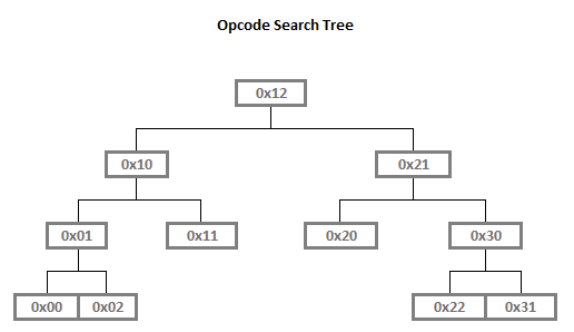
We say "almost" because if there were two child nodes for each of the nodes denoting opcodes 0x11 (vm_jump) and 0x20 (vm_encrypt), it would be an ideal binary search tree (but who says we cannot add four more instructions?).
Each node on the diagram represents a tnode structure containing all the necessary pointers, including a pointer to a small structure, which maps the operation code to real Assembly code in the virtual processor's loop:
struc instruction opcode, target
{
   .opcode dd opcode
   .target dd target
}
Thus, the first thing we do is build a table that maps all operation codes to Assembly code. The format of the table is rather simple. Each row contains the following:
- Double word operation code
- A pointer to the Assembly code (double word for the 32-bit mode or 64-bit for the long mode).
The implementation of the table in code is rather simple:
 i_load_key         instruction 0x00,\
                                run_vm.load_key
 i_nop              instruction 0x01,\
                                run_vm.nop
 i_load_data_length instruction 0x02,\
                                run_vm.load_data_length
 i_loop             instruction 0x10,\
                                run_vm.loop
 i_jump             instruction 0x11,\
                                run_vm.jmp
 i_exit             instruction 0x12,\
                                run_vm.exit
 i_encrypt          instruction 0x20,\
                                run_vm.encrypt
 i_decrement        instruction 0x21,\
                                run_vm.decrement
 i_increment        instruction 0x22,\
                                run_vm.increment
 i_load_data_byte   instruction 0x30,\
                                run_vm.load_data_byte
 i_store_data_byte  instruction 0x31,\
                                run_vm.store_data_byte
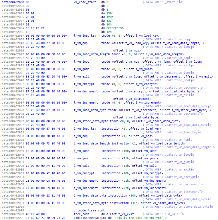
At last, we have reached the tree. Let's skip the tree building and balancing procedure, as the tree is statically allocated and as we are interested particularly in the structure itself. In the following code, we in fact create an array of tnode structures which, however, are not addressed by base+index, but are linked to a tree. The last line defines a pointer to the root node of the tree, tree_root, which refers to t_exit:
 t_load_key         tnode i_load_key,\              ; 0x00 <-\
                          0,\                       ;          |
                          0                         ;          |
 t_nop              tnode i_nop,\                   ; 0x01     | <-\
                          t_load_key,\              ; ---------/   |
                          t_load_data_length        ; ---------\   |
 t_load_data_length tnode i_load_data_length,\      ; 0x02   <-/   |
                          0,\                       ;              |
                          0                         ;              |
 t_loop             tnode i_loop,\                  ; 0x10         | <-\
                          t_nop,\                   ; -------------/   |
                          t_jmp                     ; --------\        |
 t_jmp              tnode i_jump,\                  ; 0x11  <-/        |
                          0,\                       ;                  |
                          0                         ;                  |
 t_exit             tnode i_exit,\                  ; 0x12             |
                          t_loop,\                  ; -----------------/
                          t_decrement               ; --------\
 t_encrypt          tnode i_encrypt,\               ; 0x20    | <-\
                          0,\                       ;         |   |
                          0                         ;         |   |
 t_decrement        tnode i_decrement,\             ; 0x21  <-/   |
                          t_encrypt,\               ; ------------/
                          t_load_data_byte          ; --------\
 t_increment        tnode i_increment,\             ; 0x22    | <-\
                          0,\                       ;         |   |
                          0                         ;         |   |
 t_load_data_byte   tnode i_load_data_byte,\        ; 0x30  <-/   |
                          t_increment,\             ; ------------/
                          t_store_data_byte         ; --------\
 t_store_data_byte  tnode i_store_data_byte,\       ; 0x31  <-/
                          0,\
                          0

tree_root dd t_exit
Once compiled, the data section of the executable would look like this: