We can work with the hardware in C (setting and reading pins and counters) in one of three ways: using direct calls to the registers (INA, DIRA, etc.), using the simpletools utility library, and using C code and injecting PASM code in critical sections. This is known as inline assembler mode.
Let’s begin with the simpler library method and then move on to the others.
We will write an SPI master and slave and put each in its own cog (see Section 7.1 for details on SPI). The SPI slave stands in for a data acquisition device that produces data. The SPI master is the interface to that “device.” The main cog works only with the SPI master to receive data and process, print, or store it.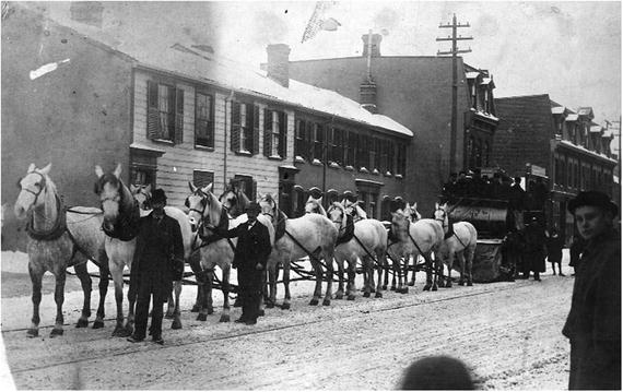
Figure 15-1
Twelve-horse team pulling snow sweeper. Toronto, 1891. From City of Toronto archives. Image in public domain.
https://commons.wikimedia.org/wiki/File%3ATwelve_horse_team_pulling_snow_sweeper.jpg
.
15.1 Referencing Hardware in C
By including the propeller.h library, the following functions and variables
are available (unlike Spin and PASM, these are case-sensitive):
- DIRA sets the direction of the 32 I/O pins. If a bit N is a 1, then that pin will be an output. All cogs have their own copy of the DIRA register. More than one cog can set a pin as output, and if any of those cogs drives the pin high (by setting that bit in the OUTA register), then that pin will go high.
- OUTA sets the value of pin N to either high or low by setting the bit in that position to 1 or 0, respectively. The pin itself will be driven high or low only if the associated bit in the DIRA register is a 1.
- INA (read-only) reflects the state of the pins. If the pin is high, the bit in that position will be a 1.
- CNT (read-only) is the value of the internal counter, which increments once each clock cycle.
- waitcnt is like Spin’s waitcnt; it takes one argument, target, and the cog is paused until the counter equals the target value. waitcnt2 is like the PASM waitcnt, with two arguments: a target value and a delta value. The cog is paused until the target count is reached. The target is incremented by delta for repeated and reliable delays.
- locknew, lockret, lockset, and lockclr are all as in Spin and PASM .
- C has some bitwise operators such as AND (&), OR (|), and XOR (∧), and shift left (<<) and shift right (>>). It is missing the rotate left and right operators of Spin and PASM, the reverse bits operator, and the arithmetic shift operator. There are functions for performing those operations in C (see http://graphics.stanford.edu/~seander/bithacks.html ).
15.2 simpletools Library
By including the
simpletools library
(with #include <simpletools.h>), you have access to a number of functions that simplify hardware manipulations. However, the authors of simpletools warn that it is best to use these functions in straight C code (LMM-only mode). This is because the library is too large to fit in a cog (remember, cog memory is limited to 496 longs). The library consists of a number of functions and variables.1
For example, set a pin with high(N), low(N), or toggle(N). Get the value of an input pin with v = input(pin). There are more-complex ways to set the direction and get the state of a single pin or of multiple pins. There are functions to use the I2C and SPI protocols as well as a full duplex serial port.
Flashing an LED on the QuickStart board (from
http://learn.parallax.com/tutorials
) is self-explanatory, as shown in Listing 15-1.
1 #include " simpletools.h"
2 #define LED0 16 # pin number for LED0 on Quickstart board.
3 int main ()
4 {
5 while (1) {
6 high (LED0);
7 pause (100) ; // Wait 100 ms (1/10 sec)
8 low (LED0);
9 pause (100) ;
10 }
11 }
Listing 15-1
Hello Blinky: Using simpletools.h to Toggle an LED
15.3 Using the Registers Directly
Particularly in Cog-C mode or whenever speed or flexibility is an issue, you will want to address the input and output registers directly.
15.3.1 Set a Pin
Set a bit, as shown in Listing 15-2.
1 #include <propeller.h>
2 #define LED0 16 // pin number for LED0 on Quickstart board.
3 #define LED0MASK (1U << LED0)
4 int main () {
5 unsigned int delayTime = CLKFREQ /2;
6 OUTA = 0; // set all bits to zero
7 DIRA |= LED0MASK ; // set pin 16 to output
8 while (1) {
9 OUTA ^= LED0MASK ; // toggle pin 16
10 waitcnt (CNT + delayTime);
11 }
12 }
Listing 15-2
Setting a Pin in C Using the OUTA Register
- Line 3: Create a mask where bit 16 is high and the others are low.
- Lines 6–7: Set the output register to all 0s and then set the output direction for pin 16 to 1. The expression DIRA |= LED0MASK will perform a bitwise OR of the DIRA register and the LED0MASK and assign the result back to DIRA. The result is that bit 16 in DIRA is set to 1 (output).
- Line 9 : Perform an exclusive OR of OUTA and LED0MASK. In an exclusive OR, compare the two arguments bit by bit, and return a 1 if and only if one of the two bits is 1. If both are 0 or both are 1, then the bit is set to 0. Thus, as bit 16 of LED0MASK is always 1, if bit 16 of OUTA is 0, then the exclusive OR will set bit 16 of OUTA to 1 (1∧0 = 1). If bit 16 of OUTA is 1, then the exclusive OR will set it to 0 (1∧1 = 0).
15.3.2 Read a Pin
The QuickStart board doesn’t have a button, but it has a touchpad. Here you set the touchpad pin high and read its value after a short time. If you are touching the pad, then the conduction of your skin will quickly force the pin low. If you aren’t touching it, then the pin will remain high for a long time (it will eventually decay to low because there is a large resistor to ground that will eventually pull it low).
In Listing 15-3 we toggle the LED every time we touch pad 0.
1 #include <propeller.h>
2 #define LED0 16 // pin number for LED0 on Quickstart board.
3 #define LED0Mask (1U << LED0)
4 #define PAD0 0 // pin number for PAD0 on Quickstart board.
5 #define PAD0Mask (1U << PAD0)
6 int main ()
7 {
8 DIRA = 0;
9 OUTA = 0;
10 DIRA |= LED0Mask ;
11 OUTA |= LED0Mask ; // illuminate LED0
12 while (1) {
13 waitcnt (CNT + CLKFREQ /10) ; // don 't do this too quickly ...
14 DIRA |= PAD0Mask ; // set to output
15 OUTA |= PAD0Mask ; // set pad0 high
16 DIRA ^= PAD0Mask ; // set pad0 back to input
17 waitcnt (CNT + CLKFREQ /1000) ;
18 if (INA & PAD0Mask) // still high - no touch
19 continue ;
20 OUTA ^= LED0Mask ;
21 }
22 }
Listing 15-3
Toggle an LED
Using Registers in C
- Lines 8–11: Set the output state register OUTA and the direction register DIRA to illuminate the LED.
- Lines 13–15: Set the pad 0 pin to output, raise it high, and set it back to input.
- Lines 16– 19 : Wait 1ms and check the value of the pad 0 pin. The INA register bit 0 will reflect the value of pin 0. Thus, if pad 0 is high (not touching the touchpad), then bit 0 of INA is high, the AND will return TRUE, and the loop will continue without changing the LED. If pad 0 is low (you touched the touchpad), the AND will return FALSE and the next statement toggling the LED will be executed instead.
15.4 Implementing SPI in Cog-C
Let’s implement the SPI protocol in Cog-C
. The main cog will start two cogs: an SPI master and an SPI slave. The master cog will request a long of data from the slave and store it to a shared array. The slave cog will wait for a request and transmit a number (our fake data is zero the first time and increments by one for each request).
In SPI, communication is controlled by the master, which asserts (lowers) the chip select (CS) line and then transmits a clock (CLK). The master reads the MISO (master in, slave out) line at the rising edge of the clock (see Figure 15-2 for an example). The slave watches for the CS line to go low and must place data on the MISO line before the rising edge of each clock cycle. We will use 32-bit wide words, with the most significant bit (MSB) transmitted first.
Figure 15-2
SPI timing diagram for the case when the clock starts out low (CPOL=0) and the data is required to be valid on a rising edge (CPHA=0)
15.5 Goals of This Chapter
In this chapter we will set all the necessary lines at the right times (and monitor and read them in the slave). We will exercise a number of ways of setting and reading particular bits in a number. In the next chapter, we will replace some of the “bit-twiddling” code with inline PASM to speed things up.
The structure of our project is as follows: a main cog will start two other cogs that communicate via SPI. The spiSlave stands in for a hardware device (for example, an analog to digital converter [ADC]) that produces data. The spiMaster will read data from the spiSlave and store it in the array data, which will be read by the main cog.
The main/controller cog and the SPI master cog must coordinate their access to the data array. We will use a lock to signal between main and spiMaster that the data array is either being filled with data by spiMaster or ready for processing by main (see Figure 15-3 for a diagram illustrating this process).
Create a new project called spi-c with four files: spi-c.c, spi-c.h, spiMaster.cogc, and spiSlave.cogc.
Because the SPI master and slave are .cogc files, they will be placed entirely in cog memory.
Figure 15-3
Structure of the SPI program
15.5.1 Main Cog (Controller)
The main cog
will control the other cogs. It will launch the SPI master and slave and process the data that the master receives from the slave. The data will be stored in a shared memory array called data[]. To ensure that the main cog knows when the master is done populating the data array, we use a lock (semaphore). Listing 15-4 has the contents of the main file, which will start up two cogs (the master and the slave) and print the contents of the data array once the master has received all the data from the slave.
1 #include <stdio.h>
2 #include <propeller.h>
3 #include "c-hw.h"
4
5 struct cogmem_t {
6 unsigned int stack [50];
7 volatile struct locker_t locker ;
8 };
9
10 /* reserve memory for spimaster cog and spislave cog */
11 struct cogmem_t mcogmem ; // master
12 struct cogmem_t scogmem ; // slave
13
14 /* functions to start cogc cogs */
15 int startSPIMaster (volatile void *p) {
16 extern unsigned int _load_start_spiMaster_cog [];
17 return cognew (_load_start_spiMaster_cog, p);
18 }
19 int startSPISlave (volatile void *p) {
20 extern unsigned int _load_start_spiSlave_cog [];
21 return cognew (_load_start_spiSlave_cog, p);
22 }
23
24 /* shared memory with cogs */
25 volatile unsigned char masterSem ;
26 volatile int data [NSAMPS_MAX];
27
28 int main ()
29 {
30 int masterCogId, slaveCogId, i;
31 unsigned int t0;
32
33 masterSem = locknew ();
34 while (lockset (masterSem)) {;} // obtain lock
35
36 /* start both cogs */
37 masterCogId = startSPIMaster (&mcogmem.locker);
38 slaveCogId = startSPISlave (&scogmem.locker);
39
40 printf (" master id = %d slave id = %d sem = %d\n", masterCogId, slaveCogId, masterSem);
41 t0 = CNT ;
42
43 lockclr (masterSem); // release lock, spimaster obtains lock
44 // wait for spimaster to release lock,
45 while (lockset (masterSem)) {;}
46 t0 = CNT - t0;
47 printf (" Time to read 128 longs = %d\n", t0);
48
49 // process array
50 for(i=0;i< NSAMPS_MAX ;i++)
51 printf ("i=%d data =%x\n", i, data [i]);
52
53 DIRA |= LED0Mask ;
54
55 while (1)
56 {
57 OUTA ^= LED0Mask ;
58 }
59 }
Listing 15-4
Contents of Main File spi-c.c
- Lines 5–12: We define a struct cogmem_t with space for the stack and a dummy entry for the locker (the PAR locker is unused because we use shared global memory). We declare and reserve memory for the two cogs as mcogmem and scogmem.
- Lines 15–22: Functions to start the master and slave cogs.
- Lines 25–26: Shared global memory. The masterSem is where the lock (semaphore) is stored that will be used by the main cog and the SPI master to control access to the data array. The data array is simply, and with great originality, named data[].
- Lines 33–34: Create a new semaphore and obtain the lock in the main cog. Thus, when we start the SPI master cog, it will sit idle attempting to obtain the lock.
- Lines 37–38: Start the two SPI cogs.
- Line 43: Release the Kraken. Upon main releasing the lock, the SPI master will obtain it, which will start a data acquisition cycle. During this time, the main cog should not touch the data array.
- Line 45: Continuously attempt to obtain the lock. Only once the SPI master has completed a data acquisition cycle will it release the lock, allowing the main cog to proceed beyond here.
- Lines 50–51: “Process” the data; print it out.
The header file (Listing 15-5) contains the pin definitions for the SPI transfer as well as a dummy locker definition (we don’t use the PAR locker; rather, we prefer to use shared memory).
1 #define NSAMPS_MAX 128
2
3 #define LED0 16
4 #define LED0Mask (1U << LED0)
5
6 #define CS 10
7 #define CLK 11
8 #define MOSI 12
9 #define MISO 13
10 #define CSMask (1U << CS)
11 #define CLKMask (1U << CLK)
12 #define MOSIMask (1U << MOSI)
13 #define MISOMask (1U << MISO)
14
15 struct locker_t {
16 };
Listing 15-5
Contents of Header File spi-c.h
15.5.2 SPI Master
The SPI master
(Listing 15-6) begins by setting the SPI pins CS, CLK, and MOSI as outputs. The CS line idles high and is active low, so set it high before setting it as an output. Next, obtain the lock, which starts an acquisition cycle. Acquisition consists of lowering the CS line and then clocking out 32 cycles on the CLK line. At each rising edge of CLK, read the value of the MISO and shift it into val. Finally, place val into data[]. After NSAMPS_MAX acquisitions, release the lock.
1 #include "c-hw.h"
2 #include <propeller.h>
3
4 extern unsigned char masterSem ;
5 extern int data [NSAMPS_MAX];
6 void main (struct locker_t *p) {
7 int i, j, val, bit ;
8 int clkwidth =50;
9
10 // init SPI pins
11 OUTA = 0;
12 OUTA |= CSMask ; // preset CS high
13 DIRA = 0;
14 DIRA |= CSMask | CLKMask | MOSIMask ; // set to outputs
15
16 while (1) {
17 while (lockset (masterSem)) { // wait to obtain lock
18 ;
19 }
20 // read from spi and write to data []
21 for (i=0; i< NSAMPS_MAX ; i++) {
22 OUTA ^= CSMask ; // lower cs
23 val = 0;
24 for (j =31; j >=0; j --) {
25 waitcnt (CNT + clkwidth); // wait
26 OUTA ^= CLKMask ; // raise clock
27
28 // get value of miso pin and put in low bit
29 bit = (INA & MISOMask) >> MISO ;
30 // shift bit into val
31 val |= bit << j;
32 waitcnt (CNT + clkwidth);
33 OUTA ^= CLKMask ; // lower clock
34 }
35 data [i] = val ;
36 OUTA ^= CSMask ; // raise cs
37 waitcnt (CNT +3* clkwidth);
38 }
39
40 lockclr (masterSem); // release lock
41 }
42 }
Listing 15-6
Contents of spiMaster.cogc
- Lines 4– 5 : The shared global memory is referenced with the extern keyword.
- Line 8: We include a short delay between clock transitions so that the SPI master and slave have enough time to read and write the bit. This is generally specified by the device. Here I set it as low as I could and not corrupt the data (I did this by trial and error).
- Lines 11–14: Set CS high by setting that bit of OUTA to 1. Set CS, CLK, and MOSI as outputs by setting those bits of DIRA to 1. (MOSI—master out, slave in—is unused here but could be used to transmit data to the slave.)
- Line 17: Wait here until the lock is obtained. masterSem is shared from the main cog.
- Lines 21–38: Acquire NSAMPS_MAX samples.
- Line 22: Lower the CS line by performing an exclusive OR of OUTA with CSMask. We already set the CS bit of OUTA high, so the XOR will lower it.
- Lines 24–24: Loop over the 32 bits, high bit to low bit.
- Lines 26 and 29: Raise the CLK line and read the value of MISO pin in the INA register. Shift it right by MISO places so that the variable bit contains either a 0 or a 1 in the lowest bit location.
- Line 31: Now shift the low bit of the variable bit left by 31, 30, …, 0 bits into val.
- Line 33: Lower the clock line and repeat.
- Lines 35 and 36: Place the number val into data[] and raise the CS line, ending the acquisition of the i-th number.
- Line 37 : Introduce a delay between acquisition requests so the SPI slave can prepare for the next request.
- Line 40: Once all NSAMPS_MAX samples have been acquired, release the lock back to the main cog for it to process the data.
15.5.3 SPI Slave (Simulated Data Producing Device)
The SPI slave (Listing 15-7) stands in for a data acquisition device or digitizer. It will wait for the CS line to go low and then place the MSB of its “data” on the MISO line. Once it sees the CLK line go high and low, it is free to put the next bit on the MISO line. Rinse and repeat 32 times.
1 #include "c-hw.h"
2 #include <propeller.h>
3
4 static _COGMEM int val ;
5 static _COGMEM int j;
6 static _COGMEM int bit ;
7 void main(struct locker_t *p) {
8 int i=0;
9 DIRA = 0;
10 OUTA = 0;
11 DIRA |= MISOMask ;
12
13 i=0;
14 while (1) {
15 val = i;
16 waitpeq(CSMask, CSMask);
17 waitpne(CSMask, CSMask);
18 for (j =31; j >=0; j --) {
19 bit = (val >> j) & 0x01; // get jth bit
20 OUTA ^= (- bit ^ OUTA) & MISOMask ; // set miso pin of outa to bit
21 waitpeq(CLKMask, CLKMask); // wait for rising clock ...
22 waitpne(CLKMask, CLKMask); // and then falling clock
23 }
24 OUTA &= ! MISOMask ; // lower miso line
25 i++;
26 }
27 }
Listing 15-7
Contents of File spiSlave.cogc
- Lines 4– 6 : static _COGMEM int val will ensure that the variable val is stored in cog memory (like a val long 0 expression in PASM) rather than being stored in hub memory. This will speed up use of that variable because hub access is slower than cog memory access.
- Line 11: Set the MISO line as an output.
- Lines 16–17: Ensure that the CS line is high and then that it is low. This high-to-low transition signals the start of an SPI data transmission cycle.
- Lines 19–20: val is the value to be transmitted to the SPI master. Get the j-th bit (starting at the most significant bit).
- Line 20: This mysterious concoction sets the bit in OUTA that corresponds to the high bit of MISOMask to the value of bit. I stole it from http://graphics.stanford.edu/~seander/bithacks.html .
- Line 21: Wait for the rising clock. In the previous line I set the MISO line to bit j of val, and on the rising clock the SPI master will read that bit value.
- Line 22 : Wait until the clock goes low. The MISO line must hold the j-th bit throughout the time the clock is high to allow the SPI master time to read it. Once the master lowers the CLK line, the slave is free to move on and put the next bit on the MISO line.
- Line 24: After all 32 bits have been transmitted, clear the MISO line (which is not strictly necessary).
15.5.4 Running the SPI Code
Let’s run the code.
master id = 1 slave id = 2 sem = 1
Time to read 128 longs = 623664
i=0 data=0
i=1 data=1
i=2 data=2
... lines deleted
i=127 data=7F
We successfully acquired 128 32-bit samples and processed them. It took about 623,000 counts, or 7.8ms, to acquire those samples (this board has an 80MHz clock). Thus, the data transfer rate is 128 samples × 32 bits/7.8ms ~ 0.525Mb/sec.
In the next chapter
, we will try to speed that up by using inline assembly instructions.
15.6 Summary
We can access all the same registers as in Spin or PASM. In particular, we can write to the outa and read from the ina registers
thusly (Listing 15-8):
1 #define INPIN 0
2 #define OUTPIN 16
3
4 int main() {
5 const inPinMask =(1U << INPIN); // create masks with pin position = 1
6 const outPinMask =(1U << OUTPIN);
7 int i, inVal ;
8
9 DIRA |= outPinMask ; // set the direction for OUTPIN to output
10 DIRA &= ~inPinMask ; // ... and the directino for INPIN to input
11
12 for (i=0; i <10; i++) {
13 waitcnt (CNT + CLKFREQ); // access the CNT register and the CLKFREQ value
14 OUTA ^= outPinMask ; // toggle the OUTPIN value
15 inVal = (INA & inPinMask) >> INPIN ; // read the INPIN value
16 printf (" inVal = %d\n", inVal);
17 }
18
19 while (1) {
20 waitpeq(inPinMask, inPinMask); // wait for INPIN to be high
21 printf(" switch pressed ...\ n");
22 waitpne(inPinMask, inPinMask); // ... and low
23 printf(" switch released ...\ n");
24 }
Listing 15-8
A C language template for setting and reading a pin
Here are some valuable fragments of C code
:
1 bitValue = 1;
2 mask1 = (1U << bitPosition1 )
3 mask2 = (1U << bitPosition2 )
4 reg |= mask1 ; // set a bit at bitPosition1
5
6 // set a bit in reg at bitPosition1 and bitPosition2
7 reg |= ( mask1 | mask2 );
8 // clear the bits at bitPosition1 and bitPosition2
9 reg &= ~( mask1 | mask2 );
10 reg ^= mask1 ; // toggle the bit at bitPosition1
11
12 // set the value of the bit at bitPosition1 in variable
13 // reg to the value of bitValue
14 reg ^= (- bitValue ^ reg) & mask1 ;
15
16 // read the value of the bit at bitPosition1 of variable reg
17 bitValue = (reg & mask1 ) >> bitPosition1 ;
18
19 // shift the value of bit 0 of bitValue into reg
20 reg = (reg << 1) | ( bitvalue & 0x01)
There is no equivalent to the sar (or “shift arithmetic right”) instruction
whereby when you shift right and the high bit is copied into the shifted positions. Rather, we must use a C construct known as a
bitfield
.
1 // Spin or PASM :
2 // i := $FF ' i is %00000000 _00000000_00000000_11111111
3 // i <<= 24 ' shift left by 24 bits
4 // now i is $FF_00_00_00 or %11111111 _00000000_00000000_00000000
5 // i ~>= 24 ' shift arithmetic right by 24 bits
6 // now i is $FF_FF_FF_FF or %11111111 _11111111_11111111_11111111
7
8 // C:
9 int i, signExtendi ;
10 i = 0xFF;
11 // i is %00000000 _00000000_00000000_11111111,
12 // which is i =255 if treated as a 32 bit number,
13 // but i=-1 ** if treated as an eight -bit number **
14 // we would like to set signExtendi to be a 32 bit value equal to -1
15 //
16 // One can inform C of the bit - size of a number by creating a
17 // struct with a field that has a ":8" (for an eight bit number)
18 struct signExtend8 {
19 signed int x :8; // the :n can be any number ...
20 } s8;
21
22 // we assign our signed eight bit number 0 x000000FF to the bitfield
23 s8.x = i;
24 // ** when we ask for it back and want it written to a 32 bit number, the
25 // compiler knows to sign extend it properly **
26 signExtendi = s8.x;
27 // now signExtendi = 0 xFFFFFFFF
Footnotes
1
See SimpleIDE/Learn/Simple%20Libraries/Utility/libsimpletools/Documentation%20simpletools%20Library.html; the SimpleIDE folder is in the Documents folder.