
 ). You can download the code examples from GitHub (
This is a tutorial on programming the Propeller microcontroller using both the C programming language and the Propeller Assembly (PASM) language. For many years after its introduction, the Propeller could be programmed in Spin and PASM; more recently, Parallax (the company behind the Propeller) has made a C compiler available. Spin and C are high-level interpreted and compiled languages, respectively. PASM is a
low-level language
, with a one-to-one correspondence between an instruction and the Propeller’s machine code.
The advantage
of PASM over Spin (and to some extent C) is speed. PASM is faster than Spin by almost two orders of magnitude, and it is faster than C by a factor of about two to five. The disadvantage of PASM is that it is cryptic and has fewer helpful shortcuts. A common task such as a loop is a single statement in C or Spin but requires more effort in PASM. Furthermore, Spin and C are well-documented, and there are a number of books and tutorials available. To learn PASM, you can turn to far fewer resources. This book is an attempt to fill that gap.
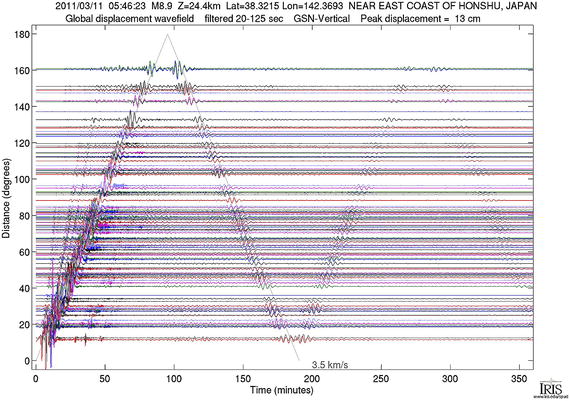
Together, we will first program a compression/decompression algorithm in Spin and then in PASM and finally in C and PASM. Compression refers to the process of taking a set of numbers and processing them in such a way that they can be stored in less space than they would have originally taken up. In lossless compression, those compressed numbers must still retain all the information in the original set of numbers (in lossy compression, we accept some degradation of the information in the numbers). The process of decompression is one in which those original numbers are generated from the compressed ones. In this book I will implement a lossless compression algorithm popular in the earthquake research community known as
delta compression
or Steim compression
(named after its originator). Steim compression can reduce the space needed to store a seismogram (the sequence of numbers from an instrument for measuring ground motion due to an earthquake) by a factor of two or three.
We will work through the code for compression and decompression in Spin and in C. I then reproduce that code in PASM. The intent is that you should be able to follow the Spin/C code if you know some programming language. Thus, when you plunge into the PASM programming, you can focus on translating what you know from the higher-level language to the lower-level one.
If the speed of compression/decompression for the Spin/C code is fast enough to handle the sampling data rates, there may be no need to use the PASM code. For higher sampling rates, we will need to use a PASM program. Nevertheless, the Spin/C code is useful to write and run as a way to generate input for testing the PASM code.
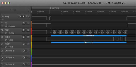
The Propeller is most often used as an embedded controller to read and write electrical signals on its input and output pins. I will demonstrate these hardware interactions in all three languages as well. In this book I start with all the interaction through the terminal. Later, so that we can debug PASM code, it can be helpful to toggle a pin to see when the code enters and exits particular parts of the program. For that a logic analyzer or an oscilloscope is needed.
In the end, I find that the most convenient combination that balances simplicity of programming language and speed of operation is to use C with particular sections written in PASM.
Disclaimer
I use and enjoy programming the Propeller, but I’m by no means an expert. If you find mistakes or have suggestions for new content, I welcome corrections and improvements.
Chapters 1–4 are an introduction to the device, to the Spin language, and to Test-Driven Development. Chapters 5–10 cover the PASM programming language and hardware interactions. Chapters 11–14 cover the C language and the various modes of programming the propeller in C: pure C, so-called Cog C, and mixed C and PASM programming. I end with a chapter on using an inline assembler that injects assembly code to speed up sections of C code.
1.1 The Propeller Eight-Cog Processor
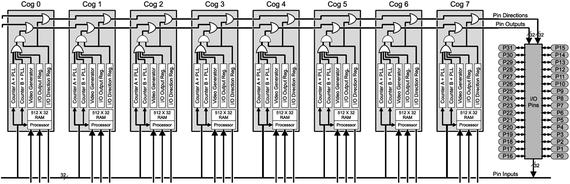
The Propeller microcontroller is a versatile and powerful device. What sets it apart from most other microcontrollers is that there are in fact eight independent, parallel, but cooperating microcontrollers (known as cogs) within each Propeller microcontroller. You use as many or as few cogs as you need to do the job (and can turn cogs on and off, as needed, to conserve power).
There is a wealth of information about the Propeller on the Parallax web site1 and even more on the forums.2
- You will need a Propeller board (available from Parallax for $25 to $80).
- You must download or purchase the Propeller manual.3
- Also take a look at the Q&A.4
- There are detailed tutorials and getting-started guides at the web site at http://learn.parallax.com .
An Opinionated Aside
The Propeller is of remarkable (unique?) design because of the eight parallel cogs, or processors. Embedded systems (programmable controllers that are often “hidden” from users but interact with the physical world through electrical signals) require careful attention to detail when it’s possible for more than one signal to arrive at nearly the same time. That worry about timing doesn’t go away with the Propeller, but it is much alleviated by having eight truly parallel processors that can monitor and respond to events independently of each other.
The other remarkable aspect of the device is that it is useful (and used) by folks in the hobby/maker/education community as well as in commercial products.
Finally, the Propeller community is fantastically helpful. Ask questions (any question, no matter how basic) on the forums, and beginners will get a friendly welcome and gentle nudge in the right direction; those with more advanced questions sometimes get a complete, tested solution!
1.1.1 Cogs
A cog is a microprocessor (one of eight within the Propeller that can be individually activated and deactivated by other cogs). You provide a cog with a set of instructions and an order in which to execute those instructions. The cogs run in parallel, meaning that all the active cogs respond to each clock cycle in parallel (more on this later). A program always starts on one cog known as the main cog. The main cog can selectively start and stop up to seven other cogs that can independently perform tasks. All the cogs have access to all the input and output lines of the Propeller.
The Propeller as a whole can run at a variety of clock speeds depending on the needs of the program and the desire for reducing power consumption (slower speeds and fewer cogs consume less power, unsurprisingly).
Each of the eight cogs of the Propeller can operate at approximately 20 million instructions per second (MIPS)
. And because the cogs run on separate pieces of hardware, the total capacity of the Propeller is something closer to 160MIPS.
- Each cog has access to all 32 input/output pins of the Propeller. Each cog has access to an internal counter that increments once per clock cycle and to two programmable counters that can be associated with pins.
- Each cog has access to a 32 kilobytes (KB) shared memory area called the hub.
- The propeller runs a Spin interpreter that converts Spin code (stored in the hub) to PASM instructions that are then copied to a cog and run there.
- Alternatively, each cog can be programmed directly in PASM; a PASM program consists of a few hundred instructions.
- Each cog has 2KB of internal memory for storing instructions and data.
PASM instructions fall into a few families.
- Assignment, addition, and subtraction.
- Bitwise logical operations (AND, OR, and so on).
- Bit manipulations (shift or rotate longs by a certain number of bits).
- Hub memory access (reading and writing to the hub).
- Waiting for a condition to be met (e.g., waiting for the counter to equal a value, waiting for a pin to equal a state).
- Changing the location where execution will continue (jumping to an address); without an explicit jump, the next instruction in memory is executed.
- Setting or clearing a shared lock in an atomic fashion.
- Starting and stopping cogs .
- Conditional execution of an instruction based on the value of two special flags, Z and C.
- Setting the Z and C flags. Many of the instructions mentioned can and do change these flags precisely for use by the conditional execution step.
In Figure 1-1, you can see the effect of clock speed on current consumption. The Propeller can dynamically change clock speed, so you could, for example, run at a slow speed (low power) while waiting for an event and then switch to a higher speed to process data.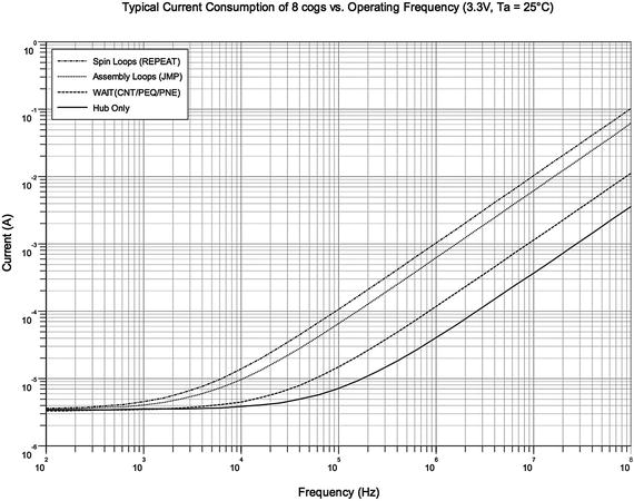
Figure 1-1
Current consumption for eight cogs under different conditions
. Horizontal axis is frequency from 100Hz to 100MHz, and vertical axis is current from 1μA to 1A. Source: Propeller P8X32A Datasheet, Parallax Semiconductor, 2011.
1.1.2 Hubs and Cogs
The hub serves as a common area with 32KB of storage (versus 2KB in each cog). Each cog keeps immediately needed instructions and data internally but can request other data and instructions from the hub as needed. The key difference between cog memory and hub memory is latency. Cog memory is available instantly; hub memory operates on a round-robin basis. Each of the eight cogs is given a window of access to the hub, and if a cog misses that window, it must wait until the hub “rotates back” to it (Figure 1-2).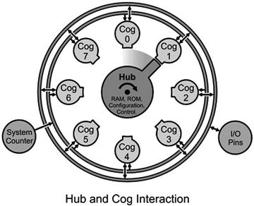
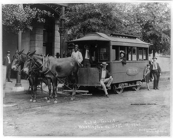
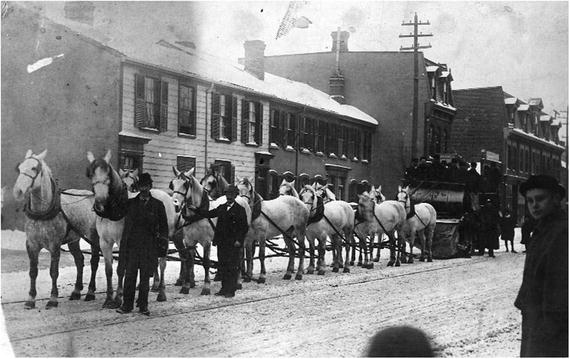
Figure 1-2
The relationship between the hub and cogs
. The hub rotates to the next cog every four clock cycles, and at that time, the cog can exchange data with the hub. Source: Propeller P8X32A Datasheet, Parallax Semiconductor, 2011.
Initially only one cog is running. You can start up a second cog, which will run at the same clock speed and in parallel to the first cog. In other words, both cogs will execute their own instructions at exactly the same time. This is particularly valuable in cases where timing is critical or in cases where you need to read data from a pin at high speed (or, more likely, if you need to do both things at once).
For example
, let’s say we want to monitor the pulse-per-second (PPS) line from a GPS receiver5 to synchronize the internal clock to an absolute time standard. At the same time, we may be reading data from a digitizer at rates of 100 kilobits per second (Kbps). This is 100,000 bits per second or approximately every 10μs. One way to structure this program would be to have two cogs running in parallel where the first does nothing but wait for the PPS line to rise and to set the clock when it does; the second cog could be independently reading the data line.
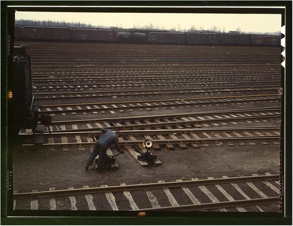
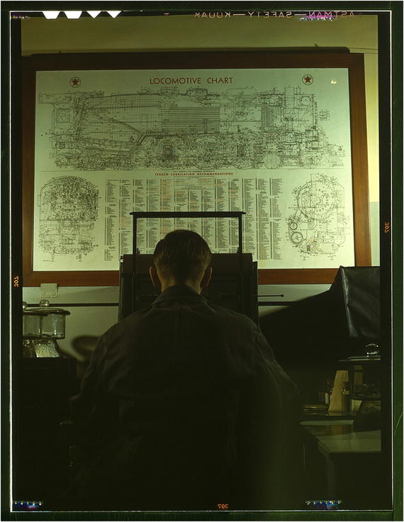
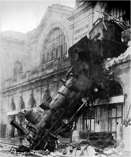
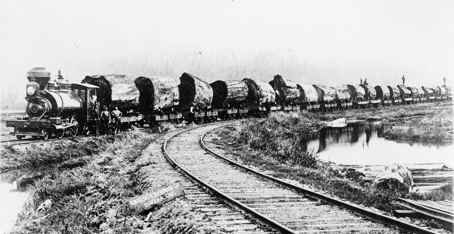
The only time that the cogs are not completely independent is when they want to access hub resources. For example, if a cog wants to write data to hub memory, it waits its turn. The hub operates in round-robin fashion and gives each of the eight cogs its window of opportunity to write to the hub (Figure 1-2 shows a railroad turntable that is analogous: the different locomotives can access the central hub only when it’s their turn).
Multi-core vs. single-core processors
To be fair, everything you will do with a Propeller microcontroller can be done with a single-processor machine. A single-processor machine—even a relatively simple one—can easily keep up with a 100Kbps data stream. These processors may have a counter module that could be set to be triggered by the PPS line, so you could synchronize to GPS time,
or they may be capable of setting the PPS line as a hardware interrupt that will call a synchronization subroutine when the PPS signal arrives.
There are proponents of the Propeller, and there are those who like other processors. What I find appealing about the Propeller is the elegance of separating functionally different tasks into different cogs.
1.2 Memory Layout
We will be doing lots of messing about with memory locations and whether a number is a byte or a long, and so on, so this section is a quick high-level introduction to what the Propeller “looks like” on the inside. There are two areas of memory that we will be dealing with. One is hub memory. This is a 32KB area of shared space where program instructions and variables, as well as special-purpose registers, are saved. We will mainly be focusing on variables’ storage and access to some of those special registers.
In the propeller, memory is addressed by byte, word (two bytes), or long (4 bytes). In hub memory, one can use all three of these memory types, but in a cog, only bytes and longs are allowed.
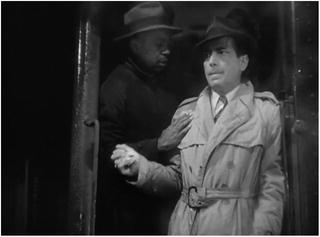
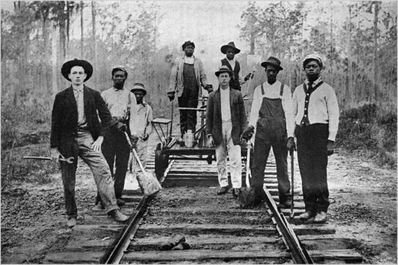
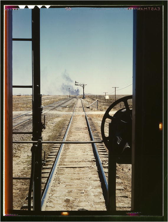
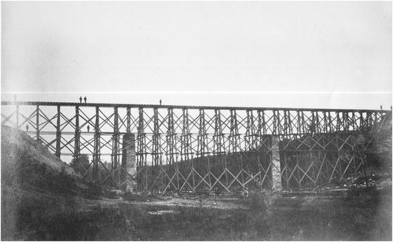
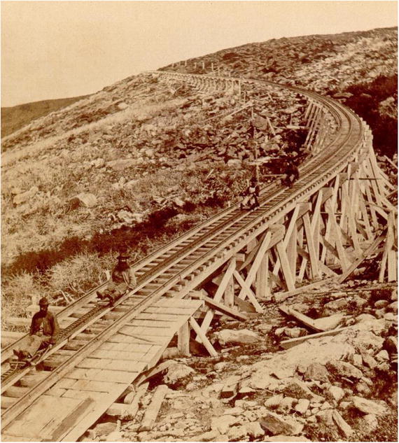
The other area of memory is cog memory. There are seven such areas available (the eighth, cog 0, is generally not programmed by us in PASM). PASM instructions are placed in that space, as well as storage for any variables used by that cog. It is important to keep in mind that this space is completely separate from the hub memory (and from the cog memory for other cogs). If you want to interact with the other cogs, you must do so by writing to and reading from hub memory. We will spend some time looking at that. Figure 1-3 shows a railroad turntable. The engines are stored on the spokes of the turntable and the central hub rotates to access them as needed, in similar fashion to the Propeller.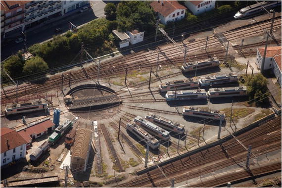
Figure 1-3
A railroad turntable. To store locomotives in a yard and to access them at any time, the central turntable would rotate to a particular set of tracks; the locomotive would drive onto the turntable, and then the turntable would rotate to another set of tracks (or would rotate 180 degrees to reverse the direction of locomotive). Source: Photograph by Jeroen Komen.
https://goo.gl/PjJhgZ
. Distributed under the Creative Commons License CC-BY-SA 2.0.
1.2.1 Hub Memory
All memory is addressed by byte. Listing 1-1 shows how memory is declared (reserved), and Figure 1-4 shows how the bytes are organized. The upper part of the code (before the DAT) is Spin code, which reserves space in hub memory; the part after the DAT is PASM code, which affects memory in a cog after a cognew command. (In this and subsequent code listings, an ellipsis [...] stands in for other lines of code that I’m not showing.)
1 ...
2 VAR
3 byte packBuf [8]
4 long nSamps, sampsBuf [2]
5
6 PUB MAIN
7 packBuf[0] := $00 ’ not really necessary
8 packBuf[1] := $00
9 packBuf[2] := $00
10 packBuf[3] := $00
11 nSamps := $02
12 sampsBuf[0] := $00_14_00_72
13 sampsBuf[1] := $00_00_01_5c
14 cognew(@PROG, 0)
15 ...
16
17 DAT
18 PROG ORG 0
19 ...
20 :loop
21 ...
22 _ns res 1
23 _nsPtr res 1
24 FIT 496
Listing 1-1
Variable Declarations in Spin
All memory
is addressed by byte (in both hub and cog memory).
The variables declared as byte values (packBuf[i]) are stored in consecutive memory locations.
However, the variables declared as long values (nsamps, sampsBuf[i]) are stored at every fourth memory location (because they take up four bytes each): 0x54, 0x58, and 0x5C.
The order of memory storage follows the order of how the variables are declared in the VAR section
. In other words, because I declared nSamps first and then sampsBuf immediately after, that is how the memory will look.6
1.2.2 Cog Memory
The cog memory
is also addressed by byte, but unlike in hub memory, there is no provision to reserve byte-wide memory. Everything is stored in full longs. If you want to address a byte, you have to first address a long and then mask the eight bits corresponding to the byte of interest. Each cog has 512 longs of space (2KB), of which 496 are available to the user. The last 16 longs of cog memory are reserved for special registers (PAR, OUTA, etc.).
You put PASM instructions at address zero, and the Propeller will execute that instruction and then step to the next instruction at the next location (1 long higher), and so on. An instruction is simply a 32-bit number (a very special number where every bit is important and tells the Propeller to do something particular—add these numbers, copy this number there, etc.—but just a number nevertheless), which means that if execution accidentally wandered into areas where you have variables stored, the cog will try to execute those as if they were instructions.
Figure 1-4
Hub and cog memory layout from Listing 1-1. Note that memory addresses increase downward
.
1.3 Layout of This Book
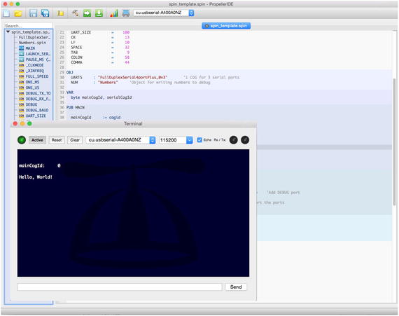
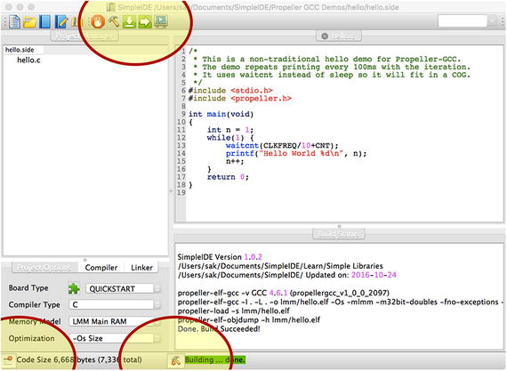
In Chapter 2 I describe the underlying process of delta compression (or Steim compression). In Chapter 3 I introduce the Spin language and provide templates for a Spin program and a PASM “Hello, World” program. Here you can verify that your hardware setup is working (you did buy a Propeller board to run your code on, right?). In Chapter 4, I introduce a simplified version of Test-Driven Development (TDD), which I use in this book. In Chapter 5, I implement the Steim compression and decompression algorithm in Spin and verify that it is working using TDD.
Chapter 6 introduces PASM, and we begin the development of Steim compression code in PASM. In Chapter 7, I introduce methods for reading and setting pins. I implement a Serial Peripheral Interface (SPI) bus in Spin and in PASM and use that bus between two cogs (one running the main Spin code and one running the Steim PASM code). Next, I introduce semaphores (or locks) and end with examples of some useful routines in Spin: multiplication, division, loops, branching.
In Chapters 8 and 9 I continue the PASM compression algorithm development using TDD. In Chapter 10, I implement the Steim decompression routines in PASM, including TDD. Chapter 11 is devoted to some simple debugging methods for PASM code.
The last section of the book is devoted to using C to perform many of the same tasks. Chapter 12 introduces C and, in particular, the Propeller-specific peculiarities we will encounter; here we program the Steim compression routine in C. In Chapter 13 I describe Cog-C mode where the compression C code is launched in a new cog. In Chapter 14, I do the same but with a mix of C and PASM.
Footnotes
5
GPS receivers are some of the most accurate clocks in existence. Even an inexpensive GPS receiver has time accuracy of a few tens of nanoseconds.
6
Don’t interleave byte and long declarations in VAR. The Spin compiler will store all longs first, then all words, and then all byte variables, even if you declare a byte variable before a long.


