Table of Contents for
Reversing: Secrets of Reverse Engineering
 Reversing: Secrets of Reverse Engineering
Published by
John Wiley & Sons, 2005
Reversing: Secrets of Reverse Engineering
Published by
John Wiley & Sons, 2005
- Copyright
- Credits
- Foreword
- Acknowledgments
- Introduction
- I. Reversing 101
- 1. Foundations
- 2. Low-Level Software
- 3. Windows Fundamentals
- 4. Reversing Tools
- II. Applied Reversing
- 5. Beyond the Documentation
- 6. Deciphering File Formats
- 7. Auditing Program Binaries
- 8. Reversing Malware
- III. Cracking
- 9. Piracy and Copy Protection
- 10. Antireversing Techniques
- 11. Breaking Protections
- IV. Beyond Disassembly
- 12. Reversing .NET
- 13. Decompilation
- A. Deciphering Code Structures
- B. Understanding Compiled Arithmetic
- C. Deciphering Program Data
- D. Citations
Operating systems play a key role in reversing. That's because programs are tightly integrated with operating systems, and plenty of information can be gathered by probing this interface. Moreover, the eventual bottom line of every program is in its communication with the outside world (the program receives user input and outputs data on the screen, writes to a file, and so on), which means that identifying and understanding the bridging points between application programs and the operating system is critical.
This chapter introduces the architecture of the latest generations of the Microsoft Windows operating system, which is the operating system used throughout this book. Some of this material is quite basic. If you feel perfectly comfortable with operating systems in general and with the Windows architecture in particular, feel free to skip this chapter.
It is important to realize that this discussion is really a brief overview of information that could fill several thick books. I've tried to make it as complete as possible and yet as focused on reversing as possible. If you feel as if you need additional information on certain subjects discussed in this chapter I've listed a couple of additional sources at the end of this chapter.
Before getting into the details of how Windows works, let's start by taking a quick look at how it evolved to its current architecture, and by listing its most fundamental features.
As you probably know, there used to be two different operating systems called Windows: Windows and Windows NT. There was Windows, which was branded as Windows 95, Windows 98, and Windows Me and was a descendent of the old 16-bit versions of Windows. Windows NT was branded as Windows 2000 and more recently as Windows XP and Windows Server 2003. Windows NT is a more recent design that Microsoft initiated in the early 1990s. Windows NT was designed from the ground up as a 32-bit, virtual memory capable, multithreaded and multiprocessor-capable operating system, which makes it far more suited for use with modern-day hardware and software.
Both operating systems were made compatible with the Win32 API, in order to make applications run on both operating systems. In 2001 Microsoft finally decided to eliminate the old Windows product (this should have happened much earlier in my opinion) and to only offer NT-based systems. The first general-public, consumer version of Windows NT was Windows XP, which offered a major improvement for Windows 9x users (and a far less significant improvement for users of its NT-based predecessor—Windows 2000). The operating system described in this chapter is essentially Windows XP, but most of the discussion deals with fundamental concepts that have changed very little between Windows NT 4.0 (which was released in 1996), and Windows Server 2003. It should be safe to assume that the materials in this chapter will be equally relevant to the upcoming Windows release (currently codenamed "Longhorn").
The following are the basic features of the Windows NT architecture.
Pure 32-bit Architecture Now that the transition to 64-bit computing is already well on the way this may not sound like much, but Windows NT is a pure 32-bit computing environment, free of old 16-bit relics. Current versions of the operating system are also available in 64-bit versions.
Supports Virtual-Memory Windows NT's memory manager employs a full-blown virtual-memory model. Virtual memory is discussed in detail later in this chapter.
Portable Unlike the original Windows product, Windows NT was written in a combination of C and C++, which means that it can be recompiled to run on different processor platforms. Additionally, any physical hardware access goes through a special Hardware Abstraction Layer (HAL), which isolates the system from the hardware and makes it easier to port the system to new hardware platforms.
Multithreaded Windows NT is a fully preemptive, multithreaded system. While it is true that later versions of the original Windows product were also multithreaded, they still contained nonpreemptive components, such as the 16-bit implementations of USER and GDI (the Windows GUI components). These components had an adverse effect on those systems' ability to achieve concurrency.
Multiprocessor-Capable The Windows NT kernel is multiprocessor-capable, which means that it's better suited for high-performance computing environments such as large data-center servers and other CPU-intensive applications.
Secure Unlike older versions of Windows, Windows NT was designed with security in mind. Every object in the system has an associated Access Control List (ACL) that determines which users are allowed to manipulate it. The Windows NT File System (NTFS) also supports an ACL for each individual file, and supports encryption of individual files or entire volumes.
Compatible Windows NT is reasonably compatible with older applications and is capable of running 16-bit Windows applications and some DOS applications as well. Old applications are executed in a special isolated virtual machine where they cannot jeopardize the rest of the system.
Originally, Windows NT was designed as a cross-platform operating system, and was released for several processor architectures, including IA-32, DEC Alpha, and several others. With recent versions of the operating system, the only supported 32-bit platform has been IA-32, but Microsoft now also supports 64-bit architectures such as AMD64, Intel IA-64, and Intel EMT64.
This discussion is specific to the 32-bit versions of Windows. The fact is that 64-bit versions of Windows are significantly different from a reversing standpoint, because 64-bit processors (regardless of which specific architecture) use a different assembly language. Focusing exclusively on 32-bit versions of Windows makes sense because this book only deals with the IA-32 assembly language. It looks like it is still going to take 64-bit systems a few years to become a commodity. I promise I will update this book when that happens!
Virtual memory is a fundamental concept in contemporary operating systems. The idea is that instead of letting software directly access physical memory, the processor, in combination with the operating system, creates an invisible layer between the software and the physical memory. For every memory access, the processor consults a special table called the page table that tells the process which physical memory address to actually use. Of course, it wouldn't be practical to have a table entry for each byte of memory (such a table would be larger than the total available physical memory), so instead processors divide memory into pages.
Pages are just fixed-size chunks of memory; each entry in the page table deals with one page of memory. The actual size of a page of memory differs between processor architectures, and some architectures support more than one page size. IA-32 processors generally use 4K pages, though they also support 2 MB and 4 MB pages. For the most part Windows uses 4K pages, so you can generally consider that to be the default page size.
When first thinking about this concept, you might not immediately see the benefits of using a page table. There are several advantages, but the most important one is that it enables the creation of multiple address spaces. An address space is an isolated page table that only allows access to memory that is pertinent to the current program or process. Because the process prevents the application from accessing the page table, it is impossible for the process to break this boundary. The concept of multiple address spaces is a fundamental feature in modern operating systems, because it ensures that programs are completely isolated from one another and that each process has its own little "sandbox" to run in.
Beyond address spaces, the existence of a page table also means that it is very easy to instruct the processor to enforce certain rules on how memory is accessed. For example, page-table entries often have a set of flags that determine certain properties regarding the specific entry such as whether it is accessible from nonprivileged mode. This means that the operating system code can actually reside inside the process's address space and simply set a flag in the page-table entries that restricts the application from ever accessing the operating system's sensitive data.
This brings us to the fundamental concepts of kernel mode versus user mode. Kernel mode is basically the Windows term for the privileged processor mode and is frequently used for describing code that runs in privileged mode or memory that is only accessible while the processor is in privileged mode. User mode is the nonprivileged mode: when the system is in user mode, it can only run user-mode code and can only access user-mode memory.
Paging is a process whereby memory regions are temporarily flushed to the hard drive when they are not in use. The idea is simple: because physical memory is much faster and much more expensive than hard drive space, it makes sense to use a file for backing up memory areas when they are not in use. Think of a system that's running many applications. When some of these applications are not in use, instead of keeping the entire applications in physical memory, the virtual memory architecture enables the system to dump all of that memory to a file and simply load it back as soon as it is needed. This process is entirely transparent to the application.
Internally, paging is easy to implement on virtual memory systems. The system must maintain some kind of measurement on when a page was last accessed (the processor helps out with this) and use that information to locate pages that haven't been used in a while. Once such pages are located, the system can flush their contents to a file and invalidate their page-table entries. The contents of these pages in physical memory can then be discarded and the space can be used for other purposes.
Later, when the flushed pages are accessed, the processor will generate page fault (because their page-table entries are invalid), and the system will know that they have been paged out. At this point the operating system will access the paging file (which is where all paged-out memory resides), and read the data back into memory.
One of the powerful side effects of this design is that applications can actually use more memory than is physically available, because the system can use the hard drive for secondary storage whenever there is not enough physical memory. In reality, this only works when applications don't actively use more memory than is physically available, because in such cases the system would have to move data back and forth between physical memory and the hard drive. Because hard drives are generally about 1,000 times slower than physical memory, such situations can cause systems to run incredibly slowly.
From the processor's perspective, a page fault is generated whenever a memory address is accessed that doesn't have a valid page-table entry. As end users, we've grown accustomed to the thought that a page-fault equals bad news. That's akin to saying that a bacterium equals bad news to the human body; nothing could be farther from the truth. Page faults have a bad reputation because any program or system crash is usually accompanied by a message informing us of an unhandled page fault. In reality, page faults are triggered thousands of times each second in a healthy system. In most cases, the system deals with such page faults as a part of its normal operations. A good example of a legitimate page fault is when a page has been paged out to the paging file and is being accessed by a program. Because the page's page-table entry is invalid, the processor generates a page fault, which the operating system resolves by simply loading the page's contents from the paging file and resuming the program that originally triggered the fault.
A working set is a per-process data structure that lists the current physical pages that are in use in the process's address space. The system uses working sets to determine each process's active use of physical memory and which memory pages have not been accessed in a while. Such pages can then be paged out to disk and removed from the process's working set.
It can be said that the memory usage of a process at any given moment can be measured as the total size of its working set. That's generally true, but is a bit of an oversimplification because significant chunks of the average process address space contain shared memory, which is also counted as part of the total working set size. Measuring memory usage in a virtual memory system is not a trivial task!
Probably the most important concept in memory management is the distinctions between kernel memory and user memory. It is well known that in order to create a robust operating system, applications must not be able to access the operating system's internal data structures. That's because we don't want a single programmer's bug to overwrite some important data structure and destabilize the entire system. Additionally, we want to make sure malicious software can't take control of the system or harm it by accessing critical operating system data structures.
Windows uses a 32-bit (4 gigabytes) memory address that is typically divided into two 2-GB portions: a 2-GB application memory portion, and a 2-GB shared kernel-memory portion. There are several cases where 32-bit systems use a different memory layout, but these are not common. The general idea is that the upper 2 GB contain all kernel-related memory in the system and are shared among all address spaces. This is convenient because it means that the kernel memory is always available, regardless of which process is currently running. The upper 2 GB are, of course, protected from any user-mode access.
One side effect of this design is that applications only have a 31-bit address space—the most significant bit is always clear in every address. This provides a tiny reversing hint: A 32-bit number whose first hexadecimal digit is 8 or above is not a valid user-mode pointer.
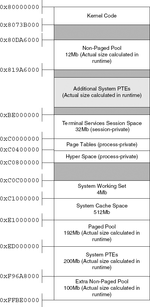
So what goes on inside those 2 GB reserved for the kernel? Those 2 GB are divided between the various kernel components. Primarily, the kernel space contains all of the system's kernel code, including the kernel itself and any other kernel components in the system such as device drivers and the like. Most of the 2 GB are divided among several significant system components. The division is generally static, but there are several registry keys that can somewhat affect the size of some of these areas. Figure 3.1 shows a typical layout of the Windows kernel address space. Keep in mind that most of the components have a dynamic size that can be determined in runtime based on the available physical memory and on several user-configurable registry keys.
Paged and Nonpaged Pools The paged pool and nonpaged pool are essentially kernel-mode heaps that are used by all the kernel components. Because they are stored in kernel memory, the pools are inherently available in all address spaces, but are only accessible from kernel mode code. The paged pool is a (fairly large) heap that is made up of conventional paged memory. The paged pool is the default allocation heap for most kernel components.The nonpaged pool is a heap that is made up of nonpageable memory. Nonpagable memory means that the data can never be flushed to the hard drive and is always kept in physical memory. This is beneficial because significant areas of the system are not allowed to use pagable memory.
System Cache The system cache space is where the Windows cache manager maps all currently cached files. Caching is implemented in Windows by mapping files into memory and allowing the memory manager to manage the amount of physical memory allocated to each mapped file. When a program opens a file, a section object (see below) is created for it, and it is mapped into the system cache area. When the program later accesses the file using the
ReadFileorWriteFileAPIs, the file system internally accesses the mapped copy of the file using cache manager APIs such asCcCopyReadandCcCopyWrite.Terminal Services Session Space This memory area is used by the kernel mode component of the Win32 subsystem:
WIN32K.SYS(see the section on the Win32 subsystem later in this chapter). The Terminal Services component is a Windows service that allows for multiple, remote GUI sessions on a single Windows system. In order to implement this feature, Microsoft has made the Win32 memory space "session private," so that the system can essentially load multiple instances of the Win32 subsystem. In the kernel, each instance is loaded into the same virtual address, but in a different session space. The session space contains theWIN32K.SYSexecutable, and various data structures required by the Win32 subsystem. There is also a special session pool, which is essentially a session private paged pool that also resides in this region.Page Tables and Hyper Space These two regions contain process-specific data that defines the current process's address space. The page-table area is simply a virtual memory mapping of the currently active page tables. The Hyper Space is used for several things, but primarily for mapping the current process's working set.
System Working Set The system working set is a system-global data structure that manages the system's physical memory use (for pageable memory only). It is needed because large parts of the contents of the kernel memory address space are pageable, so the system must have a way of keeping track of the pages that are currently in use. The two largest memory regions that are managed by this data structure are the paged pool and the system cache.
System Page-Table Entries (PTE) This is a large region that is used for large kernel allocations of any kind. This is not a heap, but rather just a virtual memory space that can be used by the kernel and by drivers whenever they need a large chunk of virtual memory, for any purpose. Internally, the kernel uses the System PTE space for mapping device driver executables and for storing kernel stacks (there is one for each thread in the system). Device drivers can allocate System PTE regions by calling the
MmAllocateMappingAddresskernel API.
The section object is a key element of the Windows memory manager. Generally speaking a section object is a special chunk of memory that is managed by the operating system. Before the contents of a section object can be accessed, the object must be mapped. Mapping a section object means that a virtual address range is allocated for the object and that it then becomes accessible through that address range.
One of the key properties of section objects is that they can be mapped to more than one place. This makes section objects a convenient tool for applications to share memory between them. The system also uses section objects to share memory between the kernel and user-mode processes. This is done by mapping the same section object into both the kernel address space and one or more user-mode address spaces. Finally, it should be noted that the term "section object" is a kernel concept—in Win32 (and in most of Microsoft's documentation) they are called memory mapped files.
There are two basic types of section objects:
Pagefile-Backed A pagefile-backed section object can be used for temporary storage of information, and is usually created for the purpose of sharing data between two processes or between applications and the kernel. The section is created empty, and can be mapped to any address space (both in user memory and in kernel memory). Just like any other paged memory region, a pagefile-backed section can be paged out to a pagefile if required.
File-Backed A file-backed section object is attached to a physical file on the hard drive. This means that when it is first mapped, it will contain the contents of the file to which it is attached. If it is writable, any changes made to the data while the object is mapped into memory will be written back into the file. A file-backed section object is a convenient way of accessing a file, because instead of using cumbersome APIs such as
ReadFileandWriteFile, a program can just directly access the data in memory using a pointer. The system uses file-backed section objects for a variety of purposes, including the loading of executable images.
A Virtual Address Descriptor (VAD) tree is the data structure used by Windows for managing each individual process's address allocation. The VAD tree is a binary tree that describes every address range that is currently in use. Each process has its own individual tree, and within those trees each entry describes the memory allocation in question. Generally speaking, there are two distinct kinds of allocations: mapped allocations and private allocations. Mapped allocations are memory-mapped files that are mapped into the address space. This includes all executables loaded into the process address space and every memory-mapped file (section object) mapped into the address space. Private allocations are allocations that are process private and were allocated locally. Private allocations are typically used for heaps and stacks (there can be multiple stacks in a single process—one for each thread).
Let's take a look at what goes on in user-mode address spaces. Of course we can't be as specific as we were in our earlier discussion of the kernel address space—every application is different. Still, it is important to understand how applications use memory and how to detect different memory types.
Private Allocations Private allocations are the most basic type of memory allocation in a process. This is the simple case where an application requests a memory block using the
VirtualAllocWin32 API. This is the most primitive type of memory allocation, because it can only allocate whole pages and nothing smaller than that. Private allocations are typically used by the system for allocating stacks and heaps (see below).Heaps Most Windows applications don't directly call
VirtualAlloc—instead they allocate a heap block by calling a runtime library function such asmallocor by calling a system heap API such asHeapAlloc. A heap is a data structure that enables the creation of multiple variable-sized blocks of memory within a larger block. Interally, a heap tries to manage the available memory wisely so that applications can conveniently allocate and free variable-sized blocks as required. The operating system offers its own heaps through theHeapAllocandHeapFreeWin32 APIs, but an application can also implement its own heaps by directly allocating private blocks using theVirtualAllocAPI.Stacks User-mode stacks are essentially regular private allocations, and the system allocates a stack automatically for every thread while it is being created.
Executables Another common allocation type is a mapped executable allocation. The system runs application code by loading it into memory as a memory-mapped file.
Mapped Views (Sections) Applications can create memory-mapped files and map them into their address space. This is a convenient and commonly used method for sharing memory between two or more programs.
The Windows Virtual Memory Manager is accessible to application programs using a set of Win32 APIs that can directly allocate and free memory blocks in user-mode address spaces. The following are the popular Win32 low-level memory management APIs.
VirtualAlloc This function allocates a private memory block within a user-mode address space. This is a low-level memory block whose size must be page-aligned; this is not a variable-sized heap block such as those allocated by
malloc(the C runtime library heap function). A block can be either reserved or actually committed. Reserving a block means that we simply reserve the address space but don't actually use up any memory. Committing a block means that we actually allocate space for it in the system page file. No physical memory will be used until the memory is actually accessed.VirtualProtect This function sets a memory region's protection settings, such as whether the block is readable, writable, or executable (newer versions of Windows actually prevent the execution of nonexecutable blocks). It is also possible to use this function to change other low-level settings such whether the block is cached by the hardware or not, and so on.
VirtualQuery This function queries the current memory block (essentially retrieving information for the block's VAD node) for various details such as what type of block it is (a private allocation, a section, or an image), and whether its reserved, committed, or unused.
VirtualFree This function frees a private allocation block (like those allocated using
VirtualAlloc).
All of these APIs deal with the currently active address space, but Windows also supports virtual-memory operations on other processes, if the process is privileged enough to do that. All of the APIs listed here have an Ex version (VirtualAllocEx, VirtualQueryEx, and so on.) that receive a handle to a process object and can operate on the address spaces of processes other than the one currently running. As part of that same functionality, Windows also offers two APIs that actually access another process's address space and can read or write to it. These APIs are ReadProcessMemory and WriteProcessMemory.
Another group of important memory-manager APIs is the section object APIs. In Win32 a section object is called a memory-mapped file and can be created using the CreateFileMapping API. A section object can be mapped into the user-mode address space using the MapViewOfFileEx API, and can be unmapped using the UnmapViewOfFile API.
The Windows kernel manages objects using a centralized object manager component. The object manager is responsible for all kernel objects such as sections, file, and device objects, synchronization objects, processes, and threads. It is important to understand that this component only manages kernel-related objects. GUI-related objects such as windows, menus, and device contexts are managed by separate object managers that are implemented inside WIN32K.SYS. These are discussed in the section on the Win32 Subsystem later in this chapter.
Viewing objects from user mode, as most applications do, gives them a somewhat mysterious aura. It is important to understand that under the hood all of these objects are merely data structures—they are typically stored in nonpaged pool kernel memory. All objects use a standard object header that describes the basic object properties such as its type, reference count, name, and so on. The object manager is not aware of any object-specific data structures, only of the generic header.
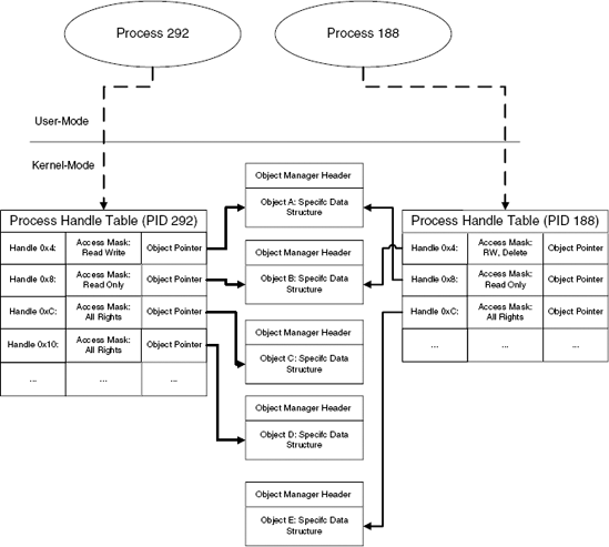
Kernel code typically accesses objects using direct pointers to the object data structures, but application programs obviously can't do that. Instead, applications use handles for accessing individual objects. A handle is a process specific numeric identifier which is essentially an index into the process's private handle table. Each entry in the handle table contains a pointer to the underlying object, which is how the system associates handles with objects. Along with the object pointer, each handle entry also contains an access mask that determines which types of operations that can be performed on the object using this specific handle. Figure 3.2 demonstrates how process each have their own handle tables and how they point to the actual objects in kernel memory.
The object's access mask is a 32-bit integer that is divided into two 16-bit access flag words. The upper word contains generic access flags such as GENERIC_READ and GENERIC_WRITE. The lower word contains object specific flags such as PROCESS_TERMINATE, which allows you to terminate a process using its handle, or KEY_ENUMERATE_SUB_KEYS, which allows you to enumerate the subkeys of an open registry key. All access rights constants are defined in WinNT.H in the Microsoft Platform SDK.
For every object, the kernel maintains two reference counts: a kernel reference count and a handle count. Objects are only deleted once they have zero kernel references and zero handles.
Some kernel objects can be named, which provides a way to uniquely identify them throughout the system. Suppose, for example, that two processes are interested in synchronizing a certain operation between them. A typical approach is to use a mutex object, but how can they both know that they are dealing with the same mutex? The kernel supports object names as a means of identification for individual objects. In our example both processes could try to create a mutex named MyMutex. Whoever does that first will actually create the MyMutex object, and the second program will just open a new handle to the object. The important thing is that using a common name effectively guarantees that both processes are dealing with the same object. When an object creation API such as CreateMutex is called for an object that already exists, the kernel automatically locates that object in the global table and returns a handle to it.
Named objects are arranged in hierarchical directories, but the Win32 API restricts user-mode applications' access to these directories. Here's a quick run-though of the most interesting directories:
- BaseNamedObjects
This directory is where all conventional Win32 named objects, such as mutexes, are stored. All named-object Win32 APIs automatically use this directory—application programs have no control over this.
- Devices
This directory contains the device objects for all currently active system devices. Generally speaking each device driver has at least one entry in this directory, even those that aren't connected to any physical device. This includes logical devices such as
Tcp, and physical devices such asHarddisk0. Win32 APIs can never directly access object in this directory—they must use symbolic links (see below).- GLOBAL??
This directory (also named
??in older versions of Windows) is the symbolic link directory. Symbolic links are old-style names for kernel objects. Old-style naming is essentially the DOS naming scheme, which you've surely used. Think about assigning each drive a letter, such as C:, and about accessing physical devices using an 8-letter name that ends with a colon, such as COM1:. These are all DOS names, and in modern versions of Windows they are linked to real devices in theDevicesdirectory using symbolic links. Win32 applications can only access devices using their symbolic link names.
Some kernel objects are unnamed and are only identified by their handles or kernel object pointers. A good example of such an object is a thread object, which is created without a name and is only represented by handles (from user mode) and by a direct pointer into the object (from kernel mode).
Processes and threads are both basic structural units in Windows, and it is crucial that you understand exactly what they represent. The following sections describe the basic concepts of processes and threads and proceed to discuss the details of how they are implemented in Windows.
A process is a fundamental building block in Windows. A process is many things, but it is predominantly an isolated memory address space. This address space can be used for running a program, and address spaces are created for every program in order to make sure that each program runs in its own address space. Inside a process's address space the system can load code modules, but in order to actually run a program, a process must have at least one thread running.
A thread is a primitive code execution unit. At any given moment, each processor in the system is running one thread, which effectively means that it's just running a piece of code; this can be either program or operating system code, it doesn't matter. The idea with threads is that instead of continuing to run a single piece of code until it is completed, Windows can decide to interrupt a running thread at any given moment and switch to another thread. This process is at the very heart of Windows' ability to achieve concurrency.
It might make it easier to understand what threads are if you consider how they are implemented by the system. Internally, a thread is nothing but a data structure that has a CONTEXT data structure telling the system the state of the processor when the thread last ran, combined with one or two memory blocks that are used for stack space. When you think about it, a thread is like a little virtual processor that has its own context and its own stack. The real physical processor switches between multiple virtual processors and always starts execution from the thread's current context information and using the thread's stack.
The reason a thread can have two stacks is that in Windows threads alternate between running user-mode code and kernel-mode code. For instance, a typical application thread runs in user mode, but it can call into system APIs that are implemented in kernel mode. In such cases the system API code runs in kernel mode from within the calling thread! Because the thread can run in both user mode and kernel mode it must have two stacks: one for when it's running in user mode and one for when it's running in kernel mode. Separating the stacks is a basic security and robustness requirement. If user-mode code had access to kernel stacks the system would be vulnerable to a variety of malicious attacks and its stability could be compromised by application bugs that could overwrite parts of a kernel stack.
The components that manage threads in Windows are the scheduler and the dispatcher, which are together responsible for deciding which thread gets to run for how long, and for performing the actual context switch when its time to change the currently running thread.
An interesting aspect of the Windows architecture is that the kernel is preemptive and interruptible, meaning that a thread can usually be interrupted while running in kernel mode just as it can be interrupted while running in user mode. For example, virtually every Win32 API is interruptible, as are most internal kernel components. Unsurprisingly, there are some components or code areas that can't be interrupted (think of what would happen if the scheduler itself got interrupted . . .), but these are usually very brief passages of code.
People sometimes find it hard to envision the process of how a multithreaded kernel achieves concurrency with multiple threads, but it's really quite simple. The first step is for the kernel to let a thread run. All this means in reality is to load its context (this means entering the correct memory address space and initializing the values of all CPU registers) and let it start running. The thread then runs normally on the processor (the kernel isn't doing anything special at this point), until the time comes to switch to a new thread. Before we discuss the actual process of switching contexts, let's talk about how and why a thread is interrupted.
The truth is that threads frequently just give up the CPU on their own volition, and the kernel doesn't even have to actually interrupt them. This happens whenever a program is waiting for something. In Windows one of the most common examples is when a program calls the GetMessage Win32 API. GetMessage is called all the time—it is how applications ask the system if the user has generated any new input events (such as touching the mouse or keyboard). In most cases, GetMessage accesses a message queue and just extracts the next event, but in some cases there just aren't any messages in the queue. In such cases, GetMessage just enters a waiting mode and doesn't return until new user input becomes available. Effectively what happens at this point is that GetMessage is telling the kernel: "I'm all done for now, wake me up when a new input event comes in." At this point the kernel saves the entire processor state and switches to run another thread. This makes a lot of sense because one wouldn't want the processor to just stall because a single program is idling at the moment—perhaps other programs could use the CPU.
Of course, GetMessage is just an example—there are dozens of other cases. Consider for example what happens when an applications performs a slow I/O operation such as reading data from the network or from a relatively slow storage device such as a DVD. Instead of just waiting for the operation to complete, the kernel switches to run another thread while the hardware is performing the operation. The kernel then goes back to running that thread when the operation is completed.
What happens when a thread doesn't just give up the processor? This could easily happen if it just has a lot of work to do. Think of a thread performing some kind of complex algorithm that involves billions of calculations. Such code could take hours before relinquishing the CPU—and could theoretically jam the entire system. To avoid such problems operating systems use what's called preemptive scheduling, which means that threads are given a limited amount of time to run before they are interrupted.
Every thread is assigned a quantum, which is the maximum amount of time the thread is allowed to run continuously. While a thread is running, the operating system uses a low-level hardware timer interrupt to monitor how long it's been running. Once the thread's quantum is up, it is temporarily interrupted, and the system allows other threads to run. If no other threads need the CPU, the thread is immediately resumed. The process of suspending and resuming the thread is completely transparent to the thread—the kernel stores the state of all CPU registers before suspending the thread and restores that state when the thread is resumed. This way the thread has no idea that is was ever interrupted.
For software developers, the existence of threads is a mixed blessing. On one hand, threads offer remarkable flexibility when developing a program; on the other hand, synchronizing multiple threads within the same programs is not easy, especially because they almost always share data structures between them. Probably one of the most important aspects of designing multithreaded software is how to properly design data structures and locking mechanisms that will ensure data validity at all times.
The basic design of all synchronization objects is that they allow two or more threads to compete for a single resource, and they help ensure that only a controlled number of threads actually access the resource at any given moment. Threads that are blocked are put in a special wait state by the kernel and are not dispatched until that wait state is satisfied. This is the reason why synchronization objects are implemented by the operating system; the scheduler must be aware of their existence in order to know when a wait state has been satisfied and a specific thread can continue execution.
Windows supports several built-in synchronization objects, each suited to specific types of data structures that need to be protected. The following are the most commonly used ones:
- Events
An event is a simple Boolean synchronization object that can be set to either True or False. An event is waited on by one of the standard Win32 wait APIs such as
WaitForSingleObjectorWaitForMultipleObjects.- Mutexes
A mutex (from mutually exclusive) is an object that can only be acquired by one thread at any given moment. Any threads that attempt to acquire a mutex while it is already owned by another thread will enter a wait state until the original thread releases the mutex or until it terminates. If more than one thread is waiting, they will each receive ownership of the mutex in the original order in which they requested it.
- Semaphores
A semaphore is like a mutex with a user-defined counter that defines how many simultaneous owners are allowed on it. Once that maximum number is exceeded, a thread that requests ownership of the semaphore will enter a wait state until one of the threads release the semaphore.
- Critical Sections
A critical section is essentially an optimized implementation of a mutex. It is logically identical to a mutex, but with the difference that it is process private and that most of it is implemented in user mode. All of the synchronization objects described above are managed by the kernel's object manager and implemented in kernel mode, which means that the system must switch into the kernel for any operation that needs to be performed on them. A critical section is implemented in user mode, and the system only switches to kernel mode if an actual wait is necessary.
In many reversing experiences, I've found that it's important to have an understanding of what happens when a process is started. The following provides a brief description of the steps taken by the system in an average process creation sequence.
The creation of the process object and new address space is the first step: When a process calls the Win32 API
CreateProcess, the API creates a process object and allocates a new memory address space for the process.CreateProcessmapsNTDLL.DLLand the program executable (the.exefile) into the newly created address space.CreateProcesscreates the process's first thread and allocates stack space for it.The process's first thread is resumed and starts running in the
LdrpInitializefunction insideNTDLL.DLL.LdrpInitializerecursively traverses the primary executable's import tables and maps into memory every executable that is required for running the primary executable.At this point control is passed into
LdrpRunInitializeRoutines, which is an internalNTDLL.DLLroutine responsible for initializing all statically linked DLLs currently loaded into the address space. The initialization process consists of calling each DLL's entry point with theDLL_PROCESS_ATTACHconstant.Once all DLLs are initialized,
LdrpInitializecalls the thread's real initialization routine, which is theBaseProcessStartfunction fromKERNEL32.DLL. This function in turn calls the executable'sWinMainentry point, at which point the process has completed its initialization sequence.
An application programming interface (API) is a set of functions that the operating system makes available to application programs for communicating with the operating system. If you're going to be reversing under Windows, it is imperative that you develop a solid understanding of the Windows APIs and of the common methods of doing things using these APIs.
I'm sure you've heard about the Win32 API. The Win32 is a very large set of functions that make up the official low-level programming interface for Windows applications. Initially when Windows was introduced, numerous programs were actually developed using the Win32 API, but as time went by Microsoft introduced simpler, higher-level interfaces that exposed most of the features offered by the Win32 API. The most well known of those interfaces is MFC (Microsoft Foundation Classes), which is a hierarchy of C++ objects that can be used for interacting with Windows. Internally, MFC uses the Win32 API for actually calling into the operating system. These days, Microsoft is promoting the use of the .NET Framework for developing Windows applications. The .NET Framework uses the System class for accessing operating system services, which is again an interface into the Win32 API.
The reason for the existence of all of those artificial upper layers is that the Win32 API is not particularly programmer-friendly. Many operations require calling a sequence of functions, often requiring the initialization of large data structures and flags. Many programmers get frustrated quickly when using the Win32 API. The upper layers are much more convenient to use, but they incur a certain performance penalty, because every call to the operating system has to go through the upper layer. Sometimes the upper layers do very little, and at other times they contain a significant amount of "bridging" code.
If you're going to be doing serious reversing of Windows applications, it is going to be important for you to understand the Win32 API. That's because no matter which high-level interface an application employs (if any), it is eventually going to use the Win32 API for communicating with the OS. Some applications will use the native API, but that's quite rare—see section below on the native API.
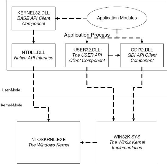
The Core Win32 API contains roughly 2000 APIs (it depends on the specific Windows version and on whether or not you count undocumented Win32 APIs). These APIs are divided into three categories: Kernel, <I>USER</I>, and <I>GDI</I>. Figure 3.3 shows the relation between the Win32 interface DLLs, NTDLL.DLL, and the kernel components.
The following are the key components in the Win32 API:
Kernel APIs (also called the BASE APIs) are implemented in the
KERNEL32.DLLmodule and include all non-GUI-related services, such as file I/O, memory management, object management, process and thread management, and so on.KERNEL32.DLLtypically calls low-level native APIs fromNTDLL.DLLto implement the various services. Kernel APIs are used for creating and working with kernel-level objects such as files, synchronization objects, and so on, all of which are implemented in the system's object manager discussed earlier.GDI APIs are implemented in the
GDI32.DLLand include low-level graphics services such as those for drawing a line, displaying a bitmap, and so on. GDI is generally not aware of the existence of windows or controls. GDI APIs are primarily implemented in the kernel, inside theWIN32K.SYSmodule. GDI APIs make system calls intoWIN32K.SYSto implement most APIs. The GDI revolves around GDI objects used for drawing graphics, such as device contexts, brushes, pens, and so on. These objects are not managed by the kernel's object manager.USER APIs are implemented in the
USER32.DLLmodule and include all higher-level GUI-related services such as window-management, menus, dialog boxes, user-interface controls, and so on. All GUI objects are drawn by USER using GDI calls to perform the actual drawing; USER heavily relies on GDI to do its business. USER APIs revolve around user-interface related objects such as windows, menus, and the like. These objects are not managed by the kernel's object manager.
The native API is the actual interface to the Windows NT system. In Windows NT the Win32 API is just a layer above the native API. Because the NT kernel has nothing to do with GUI, the native API doesn't include any graphics-related services. In terms of functionality, the native API is the most direct interface into the Windows kernel, providing interfaces for direct interfacing with the memory manager, I/O System, object manager, processes and threads, and so on.
Application programs are never supposed to directly call into the native API—that would break their compatibility with Windows 9x. This is one of the reasons why Microsoft never saw fit to actually document it; application programs are expected to only use the Win32 APIs for interacting with the system. Also, by not exposing the native API, Microsoft retained the freedom to change and revise it without affecting Win32 applications.
Sometimes calling or merely understanding a native API is crucial, in which case it is always possible to reverse its implementation in order to determine its purpose. If I had to make a guess I would say that now that the older versions of Windows are being slowly phased out, Microsoft won't be so concerned about developers using the native API and will soon publish some level of documentation for it.
Technically, the native API is a set of functions exported from both NTDLL.DLL (for user-mode callers) and from NTOSKRNL.EXE (for kernel-mode callers). APIs in the native API always start with one of two prefixes: either Nt or Zw, so that functions have names like NtCreateFile or ZwCreateFile. If you're wondering what Zw stands for—I'm sorry, I have no idea. The one thing I do know is that every native API has two versions, an Nt version and a Zw version.
In their user-mode implementation in NTDLL.DLL, the two groups of APIs are identical and actually point to the same code. In kernel mode, they are different: the Nt versions are the actual implementations of the APIs, while the Zw versions are stubs that go through the system-call mechanism. The reason you would want to go through the system-call mechanism when calling an API from kernel mode is to "prove" to the API being called that you're actually calling it from kernel mode. If you don't do that, the API might think it is being called from user-mode code and will verify that all parameters only contain user-mode addresses. This is a safety mechanism employed by the system to make sure user mode calls don't corrupt the system by passing kernel-memory pointers. For kernel-mode code, calling the Zw APIs is a way to simplify the process of calling functions because you can pass regular kernel-mode pointers.
If you'd like to use or simply understand the workings of the native API, it has been almost fully documented by Gary Nebbett in Windows NT/2000 Native API Reference. Macmillan Technical Publishing, 2000. [Nebbett].
It is important to develop a basic understanding of the system calling mechanism—you're almost guaranteed to run into code that invokes system calls if you ever step into an operating system API. A system call takes place when user-mode code needs to call a kernel-mode function. This frequently happens when an application calls an operating system API. The user-mode side of the API usually performs basic parameter validation checks and calls down into the kernel to actually perform the requested operation. It goes without saying that it is not possible to directly call a kernel function from user mode—that would create a serious vulnerability because applications could call into invalid address within the kernel and crash the system, or even call into an address that would allow them to take control of the system.
This is why operating systems use a special mechanism for switching from user mode to kernel mode. The general idea is that the user-mode code invokes a special CPU instruction that tells the processor to switch to its privileged mode (the CPUs terminology for kernel-mode execution) and call a special dispatch routine. This dispatch routine then calls the specific system function requested from user mode.
The specific details of how this is implemented have changed after Windows 2000, so I'll just quickly describe both methods. In Windows 2000 and earlier, the system would invoke interrupt 2E in order to call into the kernel. The following sequence is a typical Windows 2000 system call.
ntdll!ZwReadFile
77f8c552   mov     eax,0xa
177f8c557  lea     edx,[esp+0x4]
77f8c55b   int     2e
77f8c55d    ret    0x24
The EAX register is loaded with the service number (we'll get to this in a minute), and EDX points to the first parameter that the kernel-mode function receives. When the int 2e instruction is invoked, the processor uses the interrupt descriptor table (IDT) in order to determine which interrupt handler to call. The IDT is a processor-owned table that tells the processor which routine to invoke whenever an interrupt or an exception takes place. The IDT entry for interrupt number 2E points to an internal NTOSKRNL function called KiSystemService, which is the kernel service dispatcher. KiSystemService verifies that the service number and stack pointer are valid and calls into the specific kernel function requested. The actual call is performed using the KiServiceTable array, which contains pointers to the various supported kernel services. KiSystemService simply uses the request number loaded into EAX as an index into KiServiceTable.
More recent versions of the operating systems use an optimized version of the same mechanism. Instead of invoking an interrupt in order to perform the switch to kernel mode, the system now uses the special SYSENTER instruction in order to perform the switch. SYSENTER is essentially a high-performance kernel-mode switch instruction that calls into a predetermined function whose address is stored at a special model specific register (MSR) called SYSENTER_EIP_MSR. Needless to say, the contents of MSRs can only be accessed from kernel mode. Inside the kernel the new implementation is quite similar and goes through KiSystemService and KiServiceTable in the same way it did in Windows 2000 and older systems. The following is a typical system API in recent versions of Windows such as Windows Server 2003 and Windows XP.
ntdll!ZwReadFile:
77f4302f  mov     eax,0xbf
77f43034  mov     edx,0x7ffe0300
77f43039  call    edx
77f4303b  ret     0x24
This function calls into SharedUserData!SystemCallStub (every system call goes through this function). The following is a disassembly of the code at 7ffe0300.
SharedUserData!SystemCallStub:
7ffe0300  mov     edx,esp
7ffe0302  sysenter
7ffe0304  ret
If you're wondering why this extra call is required (instead of just invoking SYSENTER from within the system API), it's because SYSENTER records no state information whatsoever. In the previous implementation, the invocation of int 2e would store the current value of the EIP and EFLAGS registers. SYSENTER on the other hand stores no state information, so by calling into the SystemCallStub the operating system is recording the address of the current user-mode stub in the stack, so that it later knows where to return. Once the kernel completes the call and needs to go back to user mode, it simply jumps to the address recorded in the stack by that call from the API into SystemCallStub; the RET instruction at 7ffe0304 is never actually executed.
A basic understanding of executable formats is critical for reversers because a program's executable often gives significant hints about a program's architecture. I'd say that in general, a true hacker must understand the system's executable format in order to truly understand the system.
This section will cover the basic structure of Windows' executable file format: the Portable Executable (PE). To avoid turning this into a boring listing of the individual fields, I will only discuss the general concepts of portable executables and the interesting fields. For a full listing of the individual fields, you can use the MSDN (at http://msdn.microsoft.com) to look up the specific data structures specified in the section titled "Headers."
Probably the most important thing to bear in mind when dealing with executable files is that they're relocatable. This simply means that they could be loaded at a different virtual address each time they are loaded (but they can never be relocated after they have been loaded). Relocation happens because an executable does not exist in a vacuum—it must coexist with other executables that are loaded in the same address space. Sure, modern operating systems provide each process with its own address space, but there are many executables that are loaded into each address space. Other than the main executable (that's the .exe file you launch when you run a program), every program has a certain number of additional executables loaded into its address space, regardless of whether it has DLLs of its own or not. The operating system loads quite a few DLLs into each program's address space—it all depends on which OS features are required by the program.
Because multiple executables are loaded into each address space, we effectively have a mix of executables in each address space that wasn't necessarily preplanned. Therefore, it's likely that two or more modules will try to use the same memory address, which is not going to work. The solution is to relocate one of these modules while it's being loaded and simply load it in a different address than the one it was originally planned to be loaded at. At this point you may be wondering why an executable even needs to know in advance where it will be loaded? Can't it be like any regular file and just be loaded wherever there's room? The problem is that an executable contains many cross-references, where one position in the code is pointing at another position in the code. Consider, for example, the sequence that accesses a global variable.
MOV EAX, DWORD PTR [pGlobalVariable]
The preceding instruction is a typical global variable access. The storage for such a global variable is stored inside the executable image (because many variables have a preinitialized value). The question is, what address should the compiler and linker write as the address to pGlobalVariable while generating the executable? Usually, you would just write a relative address—an address that's relative to the beginning of the file. This way you wouldn't have to worry about where the file gets loaded. The problem is this is a code sequence that gets executed directly by the processor. You could theoretically generate logic that would calculate the exact address by adding the relative address to the base address where the executable is currently mapped, but that would incur a significant performance penalty. Instead, the loader just goes over the code and modifies all absolute addresses within it to make sure that they point to the right place.
Instead of going through this process every time a module is loaded, each module is assigned a base address while it is being created. The linker then assumes that the executable is going to be loaded at the base address—if it does, no relocation will take place. If the module's base address is already taken, the module is relocated.
Relocations are important for several reasons. First of all, they're the reason why there are never absolute addresses in executable headers, only in code. Whenever you have a pointer inside the executable header, it'll always be in the form of a relative virtual address (RVA). An RVA is just an offset into the file. When the file is loaded and is assigned a virtual address, the loader calculates real virtual addresses out of RVAs by adding the module's base address (where it was loaded) to an RVA.
An executable image is divided into individual sections in which the file's contents are stored. Sections are needed because different areas in the file are treated differently by the memory manager when a module is loaded. A common division is to have a code section (also called a text section) containing the executable's code and a data section containing the executable's data. In load time, the memory manager sets the access rights on memory pages in the different sections based on their settings in the section header. This determines whether a given section is readable, writable, or executable.
The code section contains the executable's code, and the data sections contain the executable's initialized data, which means that they contain the contents of any initialized variable defined anywhere in the program. Consider for example the following global variable definition:
char szMessage[] = "Welcome to my program!";
Regardless of where such a line is placed within a C/C++ program (inside or outside a function), the compiler will need to store the string somewhere in the executable. This is considered initialized data. The string and the variable that point to it (szMessage) will both be stored in an initialized data section.
Because individual sections often have different access settings defined in the executable header, and because the memory manager must apply these access settings when an executable image is loaded, sections must typically be page-aligned when an executable is loaded into memory. On the other hand, it would be wasteful to actually align executables to a page boundary on disk—that would make them significantly bigger than they need to be.
Because of this, the PE header has two different kinds of alignment fields: Section alignment and file alignment. Section alignment is how sections are aligned when the executable is loaded in memory and file alignment is how sections are aligned inside the file, on disk. Alignment is important when accessing the file because it causes some interesting phenomena. The problem is that an RVA is relative to the beginning of the image when it is mapped as an executable (meaning that distances are calculated using section alignment). This means that if you just open an executable as a regular file and try to access it, you might run into problems where RVAs won't point to the right place. This is because RVAs are computed using the file's section alignment (which is effectively its in-memory alignment), and not using the file alignment.
Dynamically linked libraries (DLLs) are a key feature in a Windows. The idea is that a program can be broken into more than one executable file, where each executable is responsible for one feature or area of program functionality. The benefit is that overall program memory consumption is reduced because executables are not loaded until the features they implement are required. Additionally, individual components can be replaced or upgraded to modify or improve a certain aspect of the program. From the operating system's standpoint, DLLs can dramatically reduce overall system memory consumption because the system can detect that a certain executable has been loaded into more than one address space and just map it into each address space instead of reloading it into a new memory location.
It is important to differentiate DLLs from build-time static libraries (.lib files) that are permanently linked into an executable. With static libraries, the code in the .lib file is statically linked right into the executable while it is built, just as if the code in the .lib file was part of the original program source code. When the executable is loaded the operating system has no way of knowing that parts of it came from a library. If another executable gets loaded that is also statically linked to the same library, the library code will essentially be loaded into memory twice, because the operating system will have no idea that the two executables contain parts that are identical.
Windows programs have two different methods of loading and attaching to DLLs in runtime. Static linking (not to be confused with compile-time static linking!) refers to a process where an executable contains a reference to another executable within its import table. This is the typical linking method that is employed by most application programs, because it is the most convenient to use. Static linking is implementing by having each module list the modules it uses and the functions it calls within each module (this is called the import table). When the loader loads such an executable, it also loads all modules that are used by the current module and resolves all external references so that the executable holds valid pointers to all external functions it plans on calling.
Runtime linking refers to a different process whereby an executable can decide to load another executable in runtime and call a function from that executable. The principal difference between these two methods is that with dynamic linking the program must manually load the right module in runtime and find the right function to call by searching through the target executable's headers. Runtime linking is more flexible, but is also more difficult to implement from the programmer's perspective. From a reversing standpoint, static linking is easier to deal with because it openly exposes which functions are called from which modules.
A PE file starts with the good old DOS header. This is a common backward-compatible design that ensures that attempts to execute PE files on DOS systems will fail gracefully. In this case failing gracefully means that you'll just get the well-known "This program cannot be run in DOS mode" message. It goes without saying that no PE executable will actually run on DOS—this message is as far as they'll go. In order to implement this message, each PE executable essentially contains a little 16-bit DOS program that displays it.
The most important field in the DOS header (which is defined in the IMAGE_DOS_HEADER structure) is the e_lfanew member, which points to the real PE header. This is an extension to the DOS header—DOS never reads it. The "new" header is essentially the real PE header, and is defined as follows.
typedef struct _IMAGE_NT_HEADERS {
   DWORD Signature;
   IMAGE_FILE_HEADER FileHeader;
   IMAGE_OPTIONAL_HEADER32 OptionalHeader;
} IMAGE_NT_HEADERS32, *PIMAGE_NT_HEADERS32;
This data structure references two data structures which contain the actual PE header. They are:
typedef struct_IMAGE_FILE_HEADER{ WORD Machine; WORD NumberOfSections; DWORD TimeDateStamp; DWORD PointerToSymbolTable; DWORD NumberOfSymbols; WORD SizeOfOptionalHeader; WORD Characteristics; } IMAGE_FILE_HEADER, *PIMAGE_FILE_HEADER; typedef struct_IMAGE_OPTIONAL_HEADER{ // Standard fields. WORD Magic; BYTE MajorLinkerVersion; BYTE MinorLinkerVersion; DWORD SizeOfCode;
DWORD   SizeOfInitializedData;
   DWORD   SizeOfUninitializedData;
   DWORD   AddressOfEntryPoint;
   DWORD   BaseOfCode;
   DWORD   BaseOfData;

   // NT additional fields.
   DWORD   ImageBase;
   DWORD   SectionAlignment;
   DWORD   FileAlignment;
   WORD    MajorOperatingSystemVersion;
   WORD    MinorOperatingSystemVersion;
   WORD    MajorImageVersion;
   WORD    MinorImageVersion;
   WORD    MajorSubsystemVersion;
   WORD    MinorSubsystemVersion;
   DWORD   Win32VersionValue;
   DWORD   SizeOfImage;
   DWORD   SizeOfHeaders;
   DWORD   CheckSum;
   WORD    Subsystem;
   WORD    DllCharacteristics;
   DWORD   SizeOfStackReserve;
   DWORD   SizeOfStackCommit;
   DWORD   SizeOfHeapReserve;
   DWORD   SizeOfHeapCommit;
   DWORD   LoaderFlags;
   DWORD   NumberOfRvaAndSizes;
   IMAGE_DATA_DIRECTORY DataDirectory[IMAGE_NUMBEROF_DIRECTORY_ENTRIES];
} IMAGE_OPTIONAL_HEADER32, *PIMAGE_OPTIONAL_HEADER32;
All of these headers are defined in the Microsoft Platform SDK in the WinNT.H header file.
Most of these fields are self explanatory, but several notes are in order. First of all, it goes without saying that all pointers within these headers (such as AddressOfEntryPoint or BaseOfCode) are RVAs and not actual pointers. Additionally, it should be noted that most of the interesting contents in a PE header actually resides in the DataDirectory, which is an array of additional data structures that are stored inside the PE header. The beauty of this layout is that an executable doesn't have to have every entry, only the ones it requires. For more information on the individual directories refer to the section on directories later in this chapter.
Imports and exports are the mechanisms that enable the dynamic linking process of executables described earlier. Consider an executable that references functions in other executables while it is being compiled and linked. The compiler and linker have no idea of the actual addresses of the imported functions. It is only in runtime that these addresses will be known. To solve this problem, the linker creates a special import table that lists all the functions imported by the current module by their names. The import table contains a list of modules that the module uses and the list of functions called within each of those modules.
When the module is loaded, the loader loads every module listed in the import table, and goes to find the address of each of the functions listed in each module. The addresses are found by going over the exporting module's export table, which contains the names and RVAs of every exported function.
When the importing module needs to call into an imported function, the calling code typically looks like this:
call [SomeAddress]
Where SomeAddress is a pointer into the executable import address table (IAT). When the modue is linked the IAT is nothing but an list of empty values, but when the module is loaded, the linker resolves each entry in the IAT to point to the actual function in the exporting module. This way when the calling code is executed, SomeAddress will point to the actual address of the imported function. Figure 3.4 illustrates this process on three executables: ImportingModule.EXE, SomeModule.DLL, and AnotherModule.DLL.
PE Executables contain a list of special optional directories, which are essentially additional data structures that executables can contain. Most directories have a special data structure that describes their contents, and none of them is required for an executable to function properly.
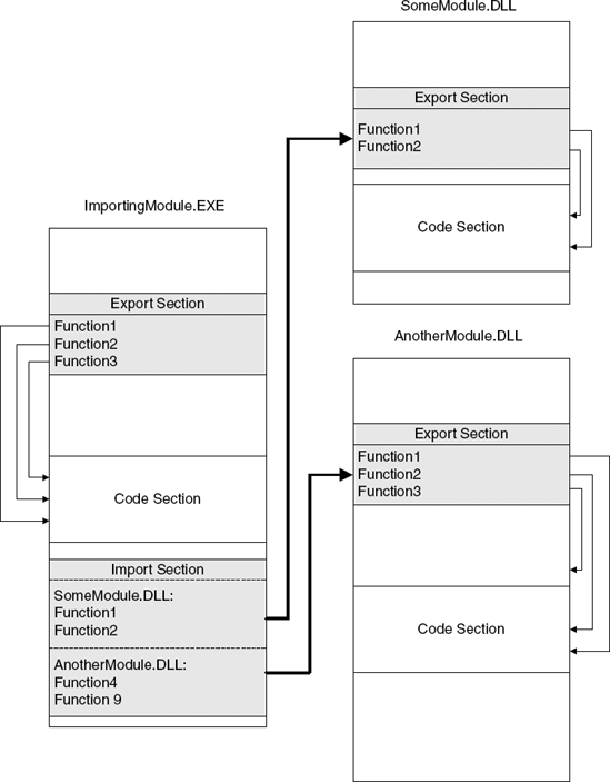
Figure 3.4. The dynamic linking process and how modules can be interconnected using their import and export tables.
Table 3.1 lists the common directories and provides a brief explanation on each one.
Table 3.1. The optional directories in the Portable Executable file format.
NAME | DESCRIPTION | ASSOCIATED DATA STRUCTURE |
|---|---|---|
Export Table | Lists the names and RVAs of all exported functions in the current module. | IMAGE_EXPORT_DIRECTORY |
Import Table | Lists the names of module and functions that are imported from the current module. For each function, the list contains a name string (or an ordinal) and an RVA that points to the current function's import address table entry. This is the entry that receives the actual pointer to the imported function in runtime, when the module is loaded. | IMAGE_IMPORT_DESCRIPTOR |
Resource Table | Points to the executable's resource directory. A resource directory is a static definition or various user-interface elements such as strings, dialog box layouts, and menus. | IMAGE_RESOURCE_DIRECTORY |
Base Relocation Table | Contains a list of addresses within the module that must be recalculated in case the module gets loaded in any address other than the one it was built for. | IMAGE_BASE_RELOCATION |
Debugging Information | Contains debugging information for the executable. This is usually presented in the form of a link to an external symbol file that contains the actual debugging information. | IMAGE_DEBUG_DIRECTORY |
Thread Local Storage Table | Points to a special thread-local section in the executable that can contain thread-local variables. This functionality is managed by the loader when the executable is loaded. | IMAGE_TLS_DIRECTORY |
Load Configuration Table | Contains a variety of image configuration elements, such as a special | IMAGE_LOAD_CONFIG_DIRECTORY |
Bound Import Table | Contains an additional import-related table that contains information on bound import entries. A bound import means that the importing executable contains actual addresses into the exporting module. This directory is used for confirming that such addresses are still valid. | IMAGE_BOUND_IMPORT_DESCRIPTOR |
Import Address Table (IAT) | Contains a list of entries for each function imported from the current module. These entries are initialized in load time to the actual addresses of the imported functions. | A list of 32-bit pointers |
Delay Import Descriptor | Contains special information that can be used for implementing a delayed-load importing mechanism whereby an imported function is only resolved when it is first called. This mechanism is not supported by the operating system and is implemented by the C runtime library. |
|
I/O can be relevant to reversing because tracing a program's communications with the outside world is much easier than doing code-level reversing, and can at times be almost as informative. In fact, some reversing sessions never reach the code-level reversing phase—by simply monitoring a program's I/O we can often answer every question we have regarding our target program.
The following sections provide a brief introduction to the various I/O channels implemented in Windows. These channels can be roughly divided into two layers: the low-level layer is the I/O system which is responsible for communicating with the hardware, and so on. The higher-level layer is the Win32 subsystem, which is responsible for implementing the GUI and for processing user input.
The I/O system is a combination of kernel components that manage the device drivers running in the system and the communication between applications and device drivers. Device drivers register with the I/O system, which enables applications to communicate with them and make generic or device-specific requests from the device. Generic requests include basic tasks such having a file system read or writing to a file. The I/O system is responsible for relaying such request from the application to the device driver responsible for performing the operation.
The I/O system is layered, which means that for each device there can be multiple device drivers that are stacked on top of each other. This enables the creation of a generic file system driver that doesn't care about the specific storage device that is used. In the same way it is possible to create generic storage drivers that don't care about the specific file system driver that will be used to manage the data on the device. The I/O system will take care of connecting the two components together, and because they use well-defined I/O System interfaces, they will be able to coexist without special modifications.
This layered architecture also makes it relatively easy to add filter drivers, which are additional layers that monitor or modify the communications between drivers and the applications or between two drivers. Thus it is possible to create generic data processing drivers that perform some kind of processing on every file before it is sent to the file system (think of a transparent file-compression or file-encryption driver).
The I/O system is interesting to us as reversers because we often monitor it to extract information regarding our target program. This is usually done by tools that insert special filtering code into the device hierarchy and start monitoring the flow of data. The device being monitored can represent any kind of I/O element such as a network interface, a high-level networking protocol, a file system, or a physical storage device.
Of course, the position in which a filter resides on the I/O stack makes a very big difference, because it affects the type of data that the filtering component is going to receive. For example, if a filtering component resides above a high-level networking protocol component (such as TCP for example), it will see the high-level packets being sent and received by applications, without the various low-level TCP, IP, or Ethernet packet headers. On the other hand, if that filter resides at the network interface level, it will receive low-level networking protocol headers such as TCP, IP, and so on.
The same concept applies to any kind of I/O channel, and the choice of where to place a filter driver really depends on what information we're looking to extract. In most cases, we will not be directly making these choices for ourselves—we'll simply need to choose the right tool that monitors things at the level that's right for our needs.
The Win32 subsystem is the component responsible for every aspect of the Windows user interface. This starts with the low-level graphics engine, the graphics device interface (GDI), and ends with the USER component, which is responsible for higher-level GUI constructs such as windows and menus, and for processing user input.
The inner workings of the Win32 subsystem is probably the least-documented area in Windows, yet I think it's important to have a general understanding of how it works because it is the gateway to all user-interface in Windows. First of all, it's important to realize that the components considered the Win32 subsystem are not responsible for the entire Win32 API, only for the USER and GDI portions of it. As described earlier, the BASE API exported from KERNEL32.DLL is implemented using direct calls into the native API, and has really nothing to do with the Win32 subsystem.
The Win32 subsystem is implemented inside the WIN32K.SYS kernel component and is controlled by the USER32.DLL and GDI32.DLL user components. Communications between the user-mode DLLs and the kernel component is performed using conventional system calls (the same mechanism used throughout the system for calling into the kernel).
It can be helpful for reversers to become familiar with USER and GDI and with the general architecture of the Win32 subsystem because practically all user-interaction flows through them. Suppose, for example, that you're trying to find the code in a program that displays a certain window, or the code that processes a certain user event. The key is to know how to track the flow of such events inside the Win32 subsystem. From there it becomes easy to find the program code that's responsible for receiving or generating such events.
Because USER and GDI are both old components that were ported from ancient versions of Windows, they don't use the kernel object manager discussed earlier. Instead they each use their own little object manager mechanism. Both USER and GDI maintain object tables that are quite similar in layout. Handles to Win32 objects such as windows and device contexts are essentially indexes into these object tables. The tables are stored and managed in kernel memory, but are also mapped into each process's address space for read-only access from user mode.
Because the USER and GDI handle tables are global, and because handles are just indexes into those tables, it is obvious that unlike kernel object handles, both USER and GDI handles are global—if more than one process needs to access the same objects, they all share the same handles. In reality, the Win32 subsystem doesn't always allow more than one process to access the same objects; the specific behavior object type.
An exception is a special condition in a program that makes it immediately jump to a special function called an exception handler. The exception handler then decides how to deal with the exception and can either correct the problem and make the program continue from the same code position or resume execution from another position. An exception handler can also decide to terminate the program if the exception cannot be resolved.
There are two basic types of exceptions: hardware exceptions and software exceptions. Hardware exceptions are exceptions generated by the processor, for example when a program accesses an invalid memory page (a page fault) or when a division by zero occurs. A software exception is generated when a program explicitly generates an exception in order to report an error. In C++ for example, an exception can be raised using the throw keyword, which is a commonly used technique for propagating error conditions (as an alternative to returning error codes in function return values). In Windows, the throw keyword is implemented using the RaiseException Win32 API, which goes down into the kernel and follows a similar code path as a hardware exception, eventually returning to user mode to notify the program of the exception.
Structured exception handling means that the operating system provides mechanisms for "distributing" exceptions to applications in an organized manner. Each thread is assigned an exception-handler list, which is a list of routines that can deal with exceptions when they occur. When an exception occurs, the operating system calls each of the registered handlers and the handlers can decide whether they would like to handle the exception or whether the system should keep on looking.
The exception handler list is stored in the thread information block (TIB) data structure, which is available from user mode and contains the following fields:
_NT_TIB:
   +0x000 ExceptionList    : 0x0012fecc
   +0x004 StackBase        : 0x00130000
   +0x008 StackLimit       : 0x0012e000
   +0x00c SubSystemTib     : (null)
   +0x010 FiberData        : 0x00001e00
   +0x010 Version          : 0x1e00
   +0x014 ArbitraryUserPointer : (null)
   +0x018 Self             : 0x7ffde000
The TIB is stored in a regular private-allocation user-mode memory. We already know that a single process can have multiple threads, but all threads see the same memory; they all share the same address space. This means that each process can have multiple TIB data structures. How does a thread find its own TIB in runtime? On IA-32 processors, Windows uses the FS segment register as a pointer to the currently active thread-specific data structures. The current thread's TIB is always available at FS:[0].
The ExceptionList member is the one of interest; it is the head of the current thread's exception handler list. When an exception is generated, the processor calls the registered handler from the IDT. Let's take a page-fault exception as an example. When an invalid memory address is accessed (an invalid memory address is one that doesn't have a valid page-table entry), the processor generates a page-fault interrupt (interrupt #14), and invokes the interrupt handler from entry 14 at the IDT. In Windows, this entry usually points to the KiTrap0E function in the Windows kernel. KiTrap0E decides which type of page fault has occurred and dispatches it properly. For user-mode page faults that aren't resolved by the memory manager (such as faults caused by an application accessing an invalid memory address), Windows calls into a user-mode exception dispatcher routine called KiUserExceptionDispatcher in NTDLL.DLL. KiUserExceptionDispatcher calls into RtlDispatchException, which is responsible for going through the linked list at ExceptionList and looking for an exception handler that can deal with the exception. The linked list is essentially a chain of _EXCEPTION_REGISTRATION_RECORD data structures, which are defined as follows:
_EXCEPTION_REGISTRATION_RECORD:
   +0x000 Next             : Ptr32 _EXCEPTION_REGISTRATION_RECORD
   +0x004 Handler          : Ptr32
A bare-bones exception handler set up sequence looks something like this:
00411F8A  push        ExceptionHandler
00411F8F  mov         eax,dword ptr fs:[00000000h]
00411F95  push        eax
00411F96  mov         dword ptr fs:[0],esp
This sequence simply adds an _EXCEPTION_REGISTRATION_RECORD entry into the current thread's exception handler list. The items are stored on the stack.
In real-life you will rarely run into simple exception handler setup sequences such as the one just shown. That's because compilers typically augment the operating system's mechanism in order to provide support for nested exception-handling blocks and for multiple blocks within the same function. In the Microsoft compilers, this is done by routing exception to the _except_handler3 exception handler, which then calls the correct exception filter and exception handler based on the current function's layout. To implement this functionality, the compiler manages additional data structures that manage the hierarchy of exception handlers within a single function. The following is a typical Microsoft C/C++ compiler SEH installation sequence:
00411F83  push        0FFFFFFFFh
00411F85  push        425090h
00411F8A  push        offset @ILT+420(__except_handler3) (4111A9h)
00411F8F  mov         eax,dword ptr fs:[00000000h]
00411F95  push        eax
00411F96  mov         dword ptr fs:[0],esp
As you can see, the compiler has extended the _EXCEPTION_REGISTRATION_RECORD data structure and has added two new members. These members will be used by _except_handler3 to determine which handler should be called.
Beyond the frame-based exception handlers, recent versions of the operating system also support a vector of exception handlers, which is a linear list of handlers that are called for every exception, regardless which code generated it. Vectored exception handlers are installed using the Win32 API AddVectoredExceptionHandler.
This concludes our (extremely brief) journey through the architecture and internals of the Windows operating system. This chapter provides the very basics that every reverser must know about the operating system he or she is using.
The bottom line is that knowledge of operating systems can be useful to reversers at many different levels. First of all, understanding the system's executable file format is crucial, because executable headers often pack quite a few hints regarding programs and their architectures. Additionally, having a basic understanding of how the system communicates with the outside world is helpful for effectively observing and monitoring applications using the various system monitoring tools. Finally, understanding the basic APIs offered by the operating system can be helpful in deciphering programs. Imagine an application making a sequence of system API calls. The application is essentially talking to the operating system, and the API is the language; if you understand the basics of the API in question, you can tune in to that conversation and find out what the application is saying. . . .