Table of Contents for
Information Theory, Coding and Cryptography
 Information Theory, Coding and Cryptography
Published by
Pearson India, 2013
Information Theory, Coding and Cryptography
Published by
Pearson India, 2013
- Cover
- Title Page
- Contents
- Foreword
- Preface
- Part A: Information Theory and Source CodinG
- Chapter 1: Probability, Random Processes, and Noise
- Chapter 2: Information Theory
- Chapter 3: Source Codes
- Part B: Error Control Coding
- Chapter 4: Coding Theory
- Chapter 5: Linear Block Codes
- Chapter 6: Cyclic Codes
- Chapter 7: BCH Codes
- Chapter 8: Convolution Codes
- Part C: Cryptography
- Chapter 9: Cryptography
- Appendix A: Some Related Mathematics
- Bibliography
- Notes
- Copyright
- Back Cover
Chapter 6
Cyclic Codes
6.1 INTRODUCTION
Cyclic code is a subclass of linear codes. Any cyclic shift of a code word results in another valid code. This feature allows easy implementation of encoding as well as syndrome computation with linear sequential circuits by employing shift registers and feedback connections. Since it possesses considerable amount of algebra inherently, there are many practical methods of decoding. Random error correction and burst error correction are possible to the large extent due to involvement of algebra. The theory of Galois field can be used effectively to study and analyze new cyclic codes.
6.2 GENERATION
If a set of n-components v = (v0,v1,v2,...,vn – 1) is cyclically shifted one place to right, another set of n-components is obtained as v1 = (vn – 1, v0, v1, v2, ..., vn – 2). This is called cyclic shift of v. If components of v are shifted by i places, we obtain

Clearly, cyclic shift of right is equivalent to cyclic shift of left.
Definition 6.1: An (n, k) linear code in C is called cyclic code, if cyclic shift of a code vector in C is also a code vector in C. This means that if the code word (v0,v1,v2,...,vn – 1) is in C then (vn – 1,v0,v1,v2,...,vn – 2) is also in C.
Method of Cyclic Codes Generation—The following steps can be used to generate a cyclic code:
- Consider a polynomial f(x) in Cn. The block length of the code is n.
- Obtain a set of polynomials by multiplying f(x) to all the possible polynomials of message u(x).
- A set of polynomials obtained in the above steps are the set of code words belonging to a cyclic code.
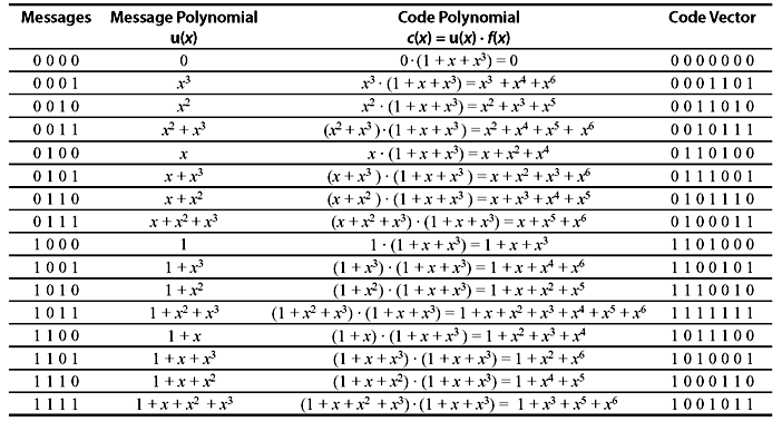
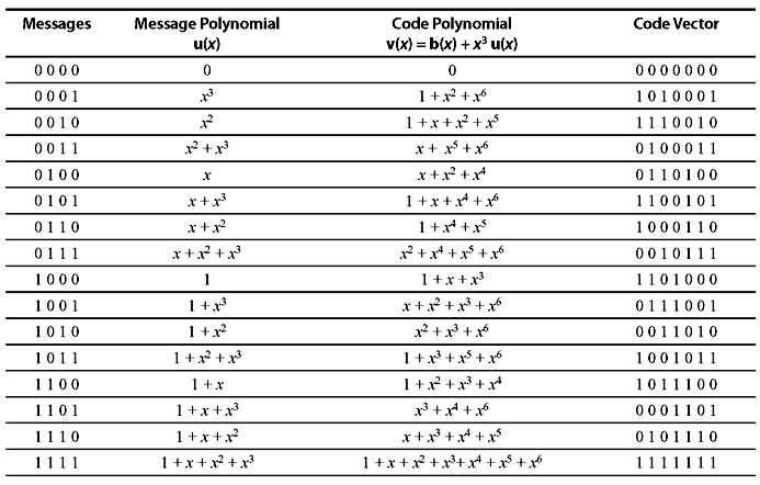
Following is an example to generate the cyclic code from 4-bit message codes with the polynomial f(x) = 1 + x + x3. As the maximum degree of the message polynomial is 3, the maximum degree of code polynomial will be 6, i. e., block length is 7.
To examine the algebraic properties of a cyclic code, let us consider the components of a code vector v = (v0,v1,v2,...,vn – 1) as the coefficients of a polynomial as follows:
where symbol x is called the indeterminate and coefficients of v(x). If vn – 1 ≠ 0, the degree of v(x) is (n – 1). Each code vector corresponds to a polynomial of degree (n – 1) or less. Similarly, the code polynomial corresponding to vi(x) (with ith shift) is

Table 6.1 (7, 4) Cyclic Code Generated by the Polynomial f(x) = 1 + x + x3
There exists an interesting algebraic property between v(x) and vi(x). Multiplying Eq. (6.1) by xi, we obtain
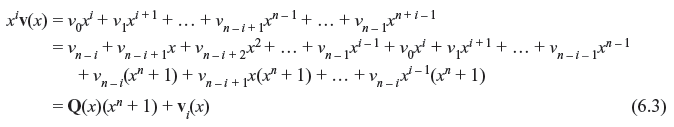
where

This means the code polynomial vi(x) is the remainder part when polynomial xiv(x) is divided by (xn + 1).
There are some important properties of cyclic code which help to implement the encoding and syndrome computation in a simple manner.
Theorem 6.1: The nonzero code polynomial of minimum degree in a cyclic code C is unique.
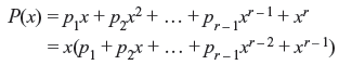
Proof: Let us consider a nonzero code polynomial P(x) = p0 + p1x + p2x2 + ... + pr – 1xr – 1 + xr of minimum degree in c. It is assumed that P(x) is not unique. Then there exists another code polynomial of minimum degree r in C, say P′(x) = p′0 + p′1x + p′2x2 + ... + p′r – 1xr – 1 + xr. Since C is linear, P(x) + P′(x) = (p0 + p′0) + (p1 + p′1)x + (p2 + p′2)x2 + ... + (pr – 1 + p′r – 1)xr – 1 is also a code polynomial of degree (r – 1) (since xr + xr = 0). If P(x) + P′(x) ≠ 0, then P(x) + P′(x) is a nonzero code polynomial of minimum degree less than r. This is not possible. Therefore P(x) + P′(x) = 0. This means P(x) = P′(x), or P(x) is unique.
Theorem 6.2: If P(x) = p0 + p1x + p2x2 + ... + pr – 1xr – 1 + xr is nonzero code polynomial of minimum degree in an (n, k) cyclic code in C, then the constant term p0 must be equal to 1.
Proof: If p0 = 0, then
Now, if P(x) is shifted cyclically to right by n – 1 places (or one place to left), a nonzero code polynomial p1 + p2x + ... + pr – 1xr – 2 + xr – 1 is obtained which has the degree less than r. This contradicts the assumption of nonzero code polynomial with a minimum degree. Hence, it is concluded that, p0 ≠ 0.
From Theorem 6.1, it may be considered that the nonzero code polynomial of minimum degree in an (n, k) cyclic code C is of the following form:
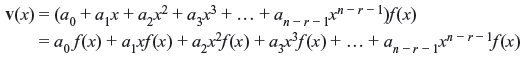
Consider the (7, 4) cyclic code as shown in Table 6.1. The nonzero code polynomial of minimum degree is f(x) = 1 + x + x3. Therefore, the polynomials xf(x), x2f(x), x3f(x), ..., xn – r – 1f(x) have the minimum degrees as r + 1, r + 2, r + 3, ..., n – 1. Now from Theorem 6.1, xf(x), x2f(x), x3f(x), ..., xn – r – 1f(x) are the cyclic shifts of f(x). Hence, they are the code polynomials in C. As C is linear, v(x), the linear combination of f(x), xf(x), x2f(x), x3f(x), ..., xn – r – 1f(x), is also a code polynomial in C, i.e.,
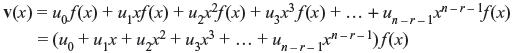
where ui = 0 or 1 for i = 0, 1, 2, ..., n – r – 1.
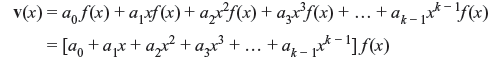
Theorem 6.3: If f(x) = 1 + f1x + f2x2 + ... + fr – 1xr – 1 + xr is the nonzero code polynomial of minimum degree in (n, k) cyclic code C, then a binary polynomial of degree n – 1 or less is a code polynomial, if and only if, it is the multiple of f(x).
Proof: Let v(x) is a binary code polynomial of degree n – 1or less, and is a multiple of f(x), such that
Since v(x) is the linear combination of f(x), xf(x), x2f(x), x3f(x), ..., xn – r – 1f(x), it is also a code polynomial in C. Now let us consider that
where b(x) is identical to 0, or it has the degree less than that of f(x). Rearranging Eq. (6.6), we obtain
Since both v(x) and a(x)f(x) are the code polynomials, b(x) must be a code polynomial. If b(x) ≠ 0, then it is a nonzero code polynomial of degree less than f(x). This contradicts the assumption that f(x) is a nonzero code polynomial of minimum degree. Hence, b(x) must be identical to 0. This proves that v(x) is the multiple of f(x).
The number of binary polynomials of degree n – 1 or less that are multiples of f(x) is 2n – r. They are the code polynomials of (n, k) cyclic code in C. Since there are 2k polynomials in (n, k) cyclic code C, 2n – r must be equal to 2k. So, (n – k) = r. Hence, an (n, k) cyclic code has the following form:

Theorem 6.4: In an (n, k) cyclic code, there exists one and only one code polynomial of degree n – k.

Proof: Every code polynomial is a multiple of f(x) and every binary polynomial of degree n – 1 or less that is a multiple of f(x) is a code polynomial.
Hence every code polynomial v(x) in an (n, k) cyclic code may be expressed as

Above equation implies that if u0, u1, u2, ..., uk – 1 are the coefficient of message digits to be encoded, the corresponding code polynomial is v(x). Therefore, the encoding can be achieved by multiplying message polynomial u(x) by f(x), and an (n, k) cyclic code can be completely specified by its nonzero code polynomial f(x) of minimum degree. The polynomial f(x) is called generator polynomial. The degree of f(x) is equal to the number of parity checks. Table 6.1 is the example of generation of an (7, 4) cyclic code, where f(x) = 1 + x + x3 is the generator polynomial.
Theorem 6.5: The generator polynomial f(x) of an (n, k) cyclic code is a factor of 1 + xn.
Proof: As the generator polynomial f(x) is of degree of n _ k, xkf(x) has the degree of n. Dividing xkf(x) by 1 + xn, we find
where fk(x) is the remainder, which is the kth cyclically right shift of f(x) as follows from Eq. (6.3). Again from Theorem 6.3, fk(x) is the multiple f(x). Let us consider fk(x) = a(x) f(x). Hence, Eq. (6.10) may be written as follows:
or
Thus f(x) is the factor of 1 + xn.
Theorem 6.6: If f(x) is a polynomial of degree n _ k, and is a factor of 1 + xn, then f(x) generates (n, k) cyclic code.
Proof: Consider k number of polynomials as f(x), xf(x), x2f(x), ..., xk – 1f(x), all of which have the degree of n – 1 or less. A linear combination of these polynomials may be considered as follows:
v(x) is also a polynomial of degree n – 1 or less and multiple of f(x). There are 2k number of code polynomials to form (n, k) cyclic code.
Now let us consider the code polynomial v(x) = v0 + v1x + v2x2 + ... + vn – 1xn – 1, then
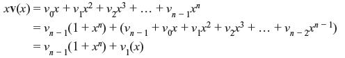
v1(x) is the cyclic shift of v(x). As both xv1(x) and 1 + xn are divisible by f(x), v1(x) is also divisible by f(x), and is linear combination of f(x), xf(x), x2f(x), ..., xk – 1f(x). Hence, v1(x) is a code polynomial. Therefore, linear code generated by f(x), xf(x), x2f(x), ..., xk – 1f(x) is the (n, k) cyclic code.
This theorem implies that any factor of 1 + xn with degree n – k generates an (n, k) cyclic code. For large values of n, there exist several numbers of codes consisting both good codes and bad codes. Selection of polynomials to generate good codes is difficult job. However, several classes of good codes have been discovered and successfully implemented.
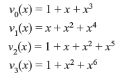
Example 6.1: Let us consider a polynomial 1 + x7, which can be factorized as follows:
There are two polynomials of degree 3, each of which can generate a (7, 4) cyclic code. Table 6.1 shows the generation of cyclic code with the generator polynomial f(x) = 1 + x + x3. Each code has been generated from the product of message polynomial and generator polynomial. Suppose message bits are 1100, then its message polynomial u(x) is 1 + x. Multiplying u(x) and f(x), the code polynomial v(x) is
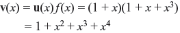
The encoded code vector is 1011100. Thus encoded cyclic code as shown in Table 6.1 has minimum distance of 3 and is a single-error-correcting code.
It may be noted that the code is not of systematic form. With the generator polynomial f(x) in a cyclic code, the code can be put into a systematic form, i.e., the rightmost k digits of code vector are unaltered information bits and leftmost n _ k digits are parity-check bits. Suppose message polynomial u(x) is given as follows:
Multiplying u(x) by xn _ k, a polynomial of degree n _ 1 is obtained as follows:

Dividing xn – ku(x) by the generator polynomial f(x), we may write
where a(x) and b(x) are the quotient and remainder, respectively. Since degree of f(x) is n – k, then degree of b(x) is n – k – 1 or less. This means
Eq. (6.11) may be rearranged as follows:
b(x) + xn – k u(x) = a(x)f(x)

The above polynomial is a multiple of generator polynomial f(x) and therefore it is a code polynomial of cyclic code. The corresponding code vector is (b0, b1, b2, ..., bn – k – 1, u0, u1, u2, ..., uk – 1). It may be noted that the code vector consists of k-unaltered message bits (u0, u1, u2, …, uk – 1) at rightmost part and n – k parity-check bits (b0, b1, b2, ..., bn – k – 1) at leftmost part, yielding a systematic form. Parity digits are generated from remainder part. To encode a systematic cyclic code, the following steps are to be followed.
- Multiply the message polynomial u(x) by xn – k.
- Obtain the remainder b(x) as parity digits from dividing xn – k u(x) by a generator polynomial f(x).
- Combine b(x) and xn – ku(x) to obtain code polynomial b(x) + xn – ku(x).
Example 6.2: Let us consider a (7, 4) cyclic code with the generator polynomial f(x) = 1 + x + x3. Let the message be 1001, i.e., the message polynomial is u(x) = 1 + x3. Obtain the systematic encoded form.
Solution: Systematic form may be obtained if b(x) is taken as remainder part of xn – ku(x)/f(x).
Therefore, the code vector v(x) = b(x) + xn – ku(x) = x + x2 + x3 + x6, and thus the encoded form will be 0111001. It may be noted that first three digits are parity digits and rest four digits are unaltered information bits. Hence, the 16 code vectors in systematic form may be listed as in Table 6.2.
Table 6.2 (7,4) Cyclic Code Generated by f(x) = 1 + x + x3
6.2.1 Generation and Parity-check Matrices
Consider an (n, k) cyclic code with the generator polynomial f(x) = 1 + f1x + f2x2 + ... + fr – 1xn – k – 1 + xn – k. We have observed that k code polynomials f(x), xf(x), x2f(x), ..., xk – 1f(x) are attributed to cyclic code C, and polynomials xf(x), x2f(x), ..., xk – 1f(x) correspond to cyclic shifts. Hence, the coefficients of these polynomials may be arranged in k × n matrix form as follows:
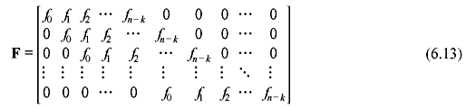
It may be noted that f0 = fn – k = 1. However, this is not in the systematic form. To get the systematic form, some operations on the matrix may be performed. It may be recalled that f(x) is one of the factor of 1 + xn, say
where h(x) is the polynomial of degree of k which may be expressed as follows:

h0 = hk = 1. It may be shown that parity-check matrix of c can be obtained from h(x). If v(x) is the code vector in C of degree n, then v(x) = a(x)f(x). Multiplying v(x) by h(x), we obtain
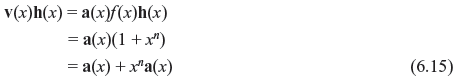
Since a(x) has the degree of k – 1 or less, powers of xk, xk + 1, xn – 1 do not exist in the polynomial a(x) + xna(x). This means the coefficients of xk, xk + 1,..., xn – 1 in the polynomial v(x)h(x) are zero. We may write that
Now we consider the polynomial xk h(x –1) that may be expressed as follows:

It may be clearly seen that xkh(x –1) is also a factor of 1 + xn. This polynomial generates an (n, n – k) cyclic code in c, with (n – k) × n generator matrix as follows:
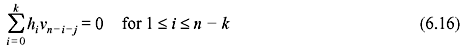
It may be observed that to satisfy Eq. (6.16) any code vector v in C must be orthogonal to every row of H. Therefore, H is the parity-check matrix in cyclic code C and row space of H is the dual code of C. As parity-check matrix is obtained from h(x), it is called the parity polynomial in C and hence a cyclic code is uniquely specified by its parity polynomial. The above derivation leads to an important property which is stated in the following theorem.
Theorem 6.7: If an (n, k) cyclic code is generated with the generator polynomial f(x), the dual code of C is cyclic and can be generated using by the polynomial xk h(x –1), where h(x) = (1 + xn)/f(x).
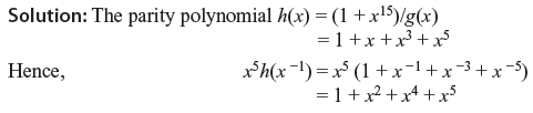
Example 6.3: Consider the (7, 4) cyclic code with the generator polynomial f(x) = 1 + x + x3. The parity polynomial is
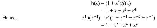
Code vectors generated by x4h(x –1) = 1 + x2 + x4 + x4 have the minimum distance of 4 and is capable of correcting any single error as well as detecting combinations of double error.
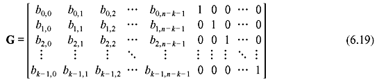
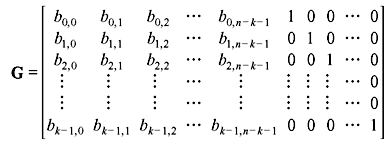
The generator matrix in systematic form can be obtained from dividing xn – k – i by generator polynomial f(x) for i = 0, 1, 2, ..., k – 1, such that
where bi(x) is remainder of the form of

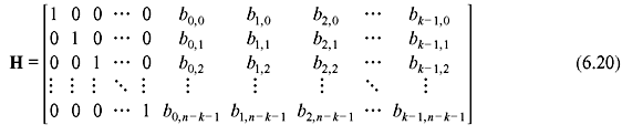
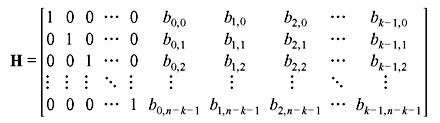
Since xn – k – i + bi(x) is the multiple of f(x) for i = 0, 1, 2, ..., k – 1, they are code polynomials and generator matrix for systematic form may be arranged in k × n matrix form as
and corresponding parity matrix is
6.2.2 Realization of Cyclic Code
We have seen that systematic form of cyclic code may be obtained by the following steps:
- Multiply the message polynomial u(x) by xn – k.
- Obtain the remainder b(x) as parity digits from dividing xn – ku(x) by a generator polynomial f(x).
- Combine b(x) and xn – ku(x) to obtain code polynomial b(x) + xn – ku(x).
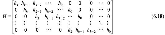
All three steps can be realized by shift registers of n – k stages with the feedback connections based on the polynomial f(x) = 1 + f1x + f2x2 + ... + fn – r – 1xn – k – 1 + xn – k. The schematic diagram of realization of encoded form of cyclic code is shown in Figure 6.1.
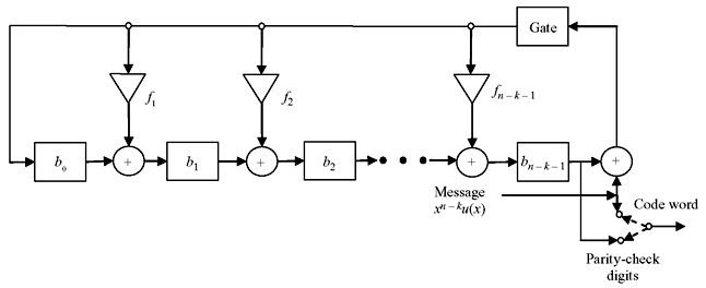
Figure 6.1 Encoding Circuit for an (n, k) Cyclic Code Generated by
First, message bits are shifted into the communication channel as well as to the gate. This is equivalent to the message polynomial of k bits, u(x) = u0 + u1x + u2x2 + ... + uk – 1xk – 1. While all the information bits are fed to the communication channel, the parity bits are simultaneously generated in the shift registers. Now the switch is turned to parity side and parity bits are shifted for n – k times to communication channel. Thus the message bits are also shifted n – k times, which is equivalent to b(x) + xn – ku(x). Next the switch is again turned to gate/message input side. Let us take the example encoding of 4-bit information to an (7, 4) cyclic code.
Example 6.4: Consider the (7, 4) cyclic code with the generator polynomial f(x) = 1 + x + x3. The message is 1010 and the circuit schematic is shown in Figure 6.2. Let us consider all the shift registers are reset to 0.
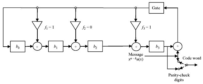
Figure 6.2 Encoding Circuit for an (7, 4) Cyclic Code Generated by f(x) = 1 + x + x3
Table 6.3 Sequence of Operations to Develop and Realize the (7, 4) Cyclic Code for Message 1010
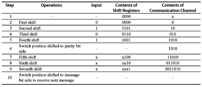
Table 6.3 shows the sequence of operations to develop and realize the (7, 4) cyclic code with systematic form. The same can also be accomplished by using parity polynomial h(x) = h0 + h1x + h2x2 + ... + hk – 1xk – 1 + hkxk. Let v = (v0, v1, v2, ..., vn – 1) be the code vector. Then, from Eq. (6.16),
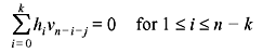
As hk = 1, it may be written that

The above equation is also termed as difference equation. In code vector vn – k, vn – k + 1, vn – k + 2, ..., vn – 1 are the information digits and v0, v1 v2, ..., vn – k – 1 are the parity digits. The encoded information may be realized by the schematic as shown in Figure 6.3. The feedback connections are made so that h0 = hk = 1. Initially the message bits are fed through gate1 as well as to the registers of k-stages, keeping gate2 as turned off. These information bits go to the communication channel also. Once all the k-bits information is entered, gate1 is turned off and gate2 is turned on. The first parity digit has been generated as follows:
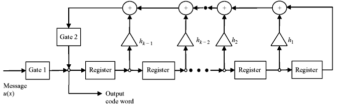
Figure 6.3 Encoding Circuit for an (n, k) Cyclic Code using Parity Polynomial h(x)
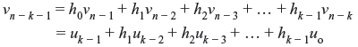
It is fed to the communication channel and also to the shift register. At the next shift, the second parity bit is generated and enters the communication channel, which is given by
It is also fed to the shift register. This process of generation of parity bits and feeding to communication channel is continued for n – k number of shifts. Thereafter, gate2 is turned off and gate1 is turned on to accept the next information block.
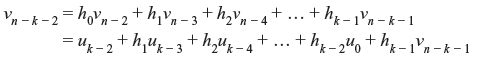
Example 6.5: Let us consider previous example of (7, 4) cyclic code with the generator polynomial f(x) = 1 + x + x3. The message is 1010. The parity polynomial h(x) will be
From Eq. (6.21), the parity bits are
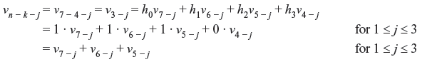
For the message 1010, v3 = 1, v4 = 0, v5 = 1, v6 = 0. The parity bits are
For j = 1, v2 = v6 + v5 + v4 = 0 + 1 + 0 = 1
For j = 2, v1 = v5 + v4 + v3 = 1 + 0 + 1 = 0
For j = 3, v0 = v4 + v3 + v2 = 0 + 1 + 1 = 0
Thus the corresponding code vector is (0 0 1 1 0 1 0) and can be realized by the circuit schematic as shown in Figure 6.4.
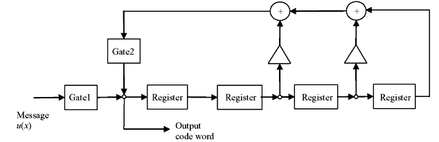
Figure 6.4 Generation of Code Vector for Message 1010
6.3 SYNDROME COMPUTATION AND ERROR DETECTION
Due to various factors, noises, and interferences, the received data may not be same as the transmitted data which is not desirable. To detect the error-free data, a procedure may be adopted which is termed as syndrome computation. Let us consider the received code vector to be r = (r0, r1, r2, ..., rn). The syndrome is defined as s = r · HT, where H is the parity-check matrix. If s is identical to zero, then received data r(x) is error-free which is acceptable to the decoder.
For a systematic cyclic code, the syndrome is the vector sum of received parity digits and parity-check digits recomputed from received information digits. The received code vector r(x) is a polynomial of degree n – 1 or less.
If r(x) is divided by the generator polynomial f(x), then r(x) may be written as
The remainder s(x) is a polynomial of degree n – k – 1 or less. The n – k coefficients of s(x) form the syndrome. It is obvious from Theorem 6.4 that s(x) is identical to zero if and only if the received polynomial r(x) is a code polynomial.
The syndrome polynomial can be realized by the circuit schematic as shown in Figure 6.5. Initially all the registers are set to 0. The received vector r(x) is shifted to the registers. As soon as the full block length is received, the register contents will be equivalent to syndrome of the received message block.
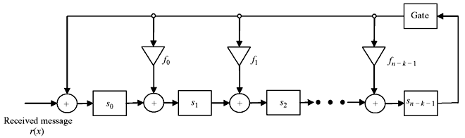
Figure 6.5 Realisation of Syndrome Polynomial
Theorem 6.8: If s(x) is the syndrome of a received polynomial r(x) = r0 + r1x + r2x2 + ... + rn – 1xn – 1, then remainder s1(x) resulting from dividing xs(x) by generator polynomial f(x) is the syndrome of r1(x) which is the cyclic shift of r(x).
Proof:
As shown in Eq. (6.3),
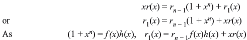
Considering f (x) as divisor polynomial,

where c(x) is the remainder resulting from dividing r1(x) by f(x) and it is equivalent to syndrome of r1(x). Eq. (6.23) may be rewritten as follows:

It is seen from above equation that c(x) is the remainder if xs(x) is divided by f(x). Therefore c(x) is the syndrome of xs(x) or s1(x). This leads to an important property of syndrome that si(x) is the syndrome of ri(x), which can be realized simply by ith shift. Furthermore this property helps to detect and correct errors from received messages.
Now consider the circuit schematic as of Figure 6.6. The received message is fed at right side i. e., after n – k registers. It is equivalent to n – k shifts of r(x) or the polynomial is xn – kr(x). After receiving full message block of r(x), the contents of the registers is say c′(x), the remainder resulting from dividing xn – kr(x) by f(x).
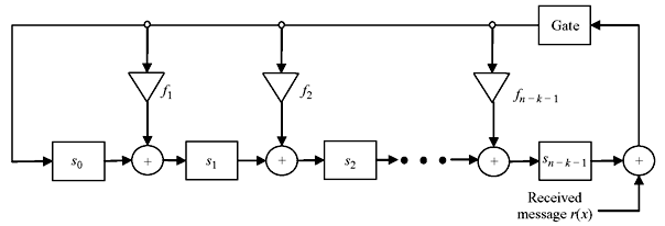
Figure 6.6 Syndrome Computation with n – k Shifts of r(x)
Eq. (6.25) implies that rn – k(x) is divided by f(x) resulting in the remainder as c′(x). This means c′(x) is the syndrome of rn – k(x), i. e., n – k times cyclic shift of r(x).
Now let us consider that v(x), r(x), and e(x) are the transmitted vector, received vector, and error, respectively, introduced in the channel. Then following relation can be written:

This shows that the syndrome is actually the remainder resulting from dividing the error polynomial by the generator polynomial f(x). Syndrome can be computed by shift registers as shown, but error pattern e(x) is unknown. Hence, decoder has to estimate e(x) based on s(x). However e(x) can be correctly determined, using decoder lookup table, if e(x) is a coset leader in standard array.
From Eq. (6.27), it may be noticed that s(x) is identical to zero, if and only if e(x) is either identical to zero or equivalent to code vector. If e(x) is identical to code vector, it is undetectable to estimate the error. Cyclic codes are very effective to detect any errors—random or burst. Multiple errors in small segment of message is termed as burst error. Error detection may be made simply by feeding all the syndrome register digits to an OR gate. If any of the syndrome digits is not 0, which is in case of presence of error, output of the OR gate is 1.
Theorem 6.9: An (n, k) cyclic code is capable of detecting any burst error of length of n _ k or less, including end-round burst.
Proof: Let us consider that the error pattern e(x) is burst type of length n – k or less. Then e(x) can be expressed as e(x) = xjq(x), for 0 ≤ j ≤ n – 1 and q(x) is a polynomial of degree n – k – 1. Since q(x) has the degree less than n – k – 1, it is not divisible by generator polynomial f(x). Also xj is not a factor or f(x); hence, xjq(x) is not divisible by f(x). Therefore e(x) is not equal to zero. This implies that (n, k) cyclic code is capable of detecting any error length n – k or less. In cyclic code, if error occurs within ith high order position and (l – i)th low order position then it is called end-round burst of length l.
Theorem 6.10: The fraction of undetectable burst length n – k + 1 is 2 –(n – k – 1).
Proof: A large percentage of error burst of n – k + 1 or longer can be detected. Let us consider burst error of length n – k + 1 starts from the ith digit position and ends at the (i + n – k)th digit position. There are possibilities of 2n – k – 1 bursts. Among these, there will one burst such that e(x) = x1f(x), which is undetectable. Therefore, fraction of undetectable error is 2 –(n – k – 1). This is applied for burst length of n – k + 1 starting from any position.
Theorem 6.11: The fraction of undetectable burst length longer than n – k + 1 is 2 –(n – k).
Proof: For burst-error length l > n – k + 1, there are 2n – k – 1 numbers of burst error starting from ith position and there will be one burst such that e(x) = x1f(x). Therefore fraction of undetectable burst starting from ith position is 2 –(n – k).
This shows that cyclic codes are very effective to detect burst errors. As example, (7, 4) cyclic code generated by the polynomial f(x) = 1 + x + x3 has the minimum distance of 3 and capable of detecting any combination of two or fewer random errors as well as burst error of length 3 or less. It is also capable of detecting many error burst of length greater than 3.
6.4 DECODING
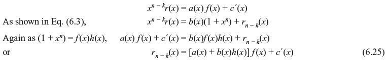
There are three basic steps to decode a cyclic code—(i) syndrome computation, (ii) obtaining error pattern, and (iii) error correction. Figure 6.7 represents the basic schematic of error detection and correction from the received data of cyclic code. The decoding operation is described as follows:
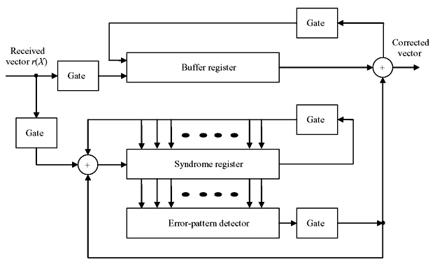
Figure 6.7 Basic Schematic of Error Detection and Correction
- The received polynomial is shifted into syndrome register from the left end. At the same time it is fed into buffer register.
- The syndrome is checked against corresponding error pattern. The error-pattern detector is a combinational circuit that is designed in such a way that its output is 1, if and only if the syndrome register contents correspond to a correctable error pattern with the error at the highest order position xn – 1. This means if the rightmost digit of received polynomial is erroneous, 1 will appear at error detector. If 0 appears at error detector, the rightmost stage of received polynomial is correct and no correction is necessary. The output of error detector is the estimated error value of the buffer.
- The first received symbol is read out of the buffer and at the same time the syndrome register is shifted once. If the first received symbol is erroneous, it is corrected by the output of the detector. The output of the detector is also fed to the syndrome register to form new syndrome shifted once to right which is free from error effect.
- The new syndrome is now compared for any error effect in similar manner which is for the second rightmost digit. Second rightmost digit is corrected and read out from buffer, and error-detector output is fed to syndrome register to form a new syndrome vector for next digit.
- This process is continued till the leftmost digit of received vector is read out with correction.
The above decoder is known as Meggitt decoder, which is applicable to any cyclic code. Its performance depends on the error-pattern detection circuit. Meggitt decoder can also be designed with the detection and correction from leftmost digit.
Example 6.6: Considering a (7, 4) cyclic code with generator polynomial f(x) = 1 + x + x3, the decoding circuit is shown in Figure 6.8. This code is capable of removing any of the single error over a block of seven digits. Suppose the received polynomial is r(x) = r0 + r1x + r2x2 + r3x3 + r4x4 + r5x5 + r6x6 from the left end of syndrome register. The seven single-error patterns and their corresponding syndromes are listed in Table 6.4.
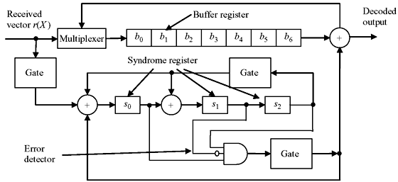
Figure 6.8 Error Correction for (7, 4) Cyclic Code with Generator Polynomial f(x) = 1 + x + x3
Table 6.4 Sequence of Syndrome Vectors
|
Error Pattern
e(x) |
Syndrome
s(x) = Remainder of e(x)/f(x) |
Syndrome Vector
|
|---|---|---|
e(x) = x6 |
s(x) = 1 + x2 |
1 0 1 |
e(x) = x5 |
s(x) = 1 + x + x2 |
1 1 1 |
e(x)= x4 |
s(x) = x + x2 |
0 1 1 |
e(x)= x3 |
s(x) = 1 + x |
1 1 0 |
e(x)= x2 |
s(x) = x2 |
0 0 1 |
e(x)= x1 |
s(x) = x |
0 1 0
|
e(x)= x0 |
s(x) = 1 |
1 0 0 |
Example 6.7: Consider the transmitted code vector to be v = 1001011 [v(x) = 1 + x3 + x5 + x6] and received vector r = 1011011 [r(x) = 1 + x2 + x3 + x5 + x6]. There is an error of single digit at location x2. When the entire received digits are loaded into buffer register, the syndrome register will contain 001. In Figure 6.9, the contents of syndrome register and buffer register are shown after every shift. Also error location has been shown for each shift. It may be noticed that after four shifts the error comes out of buffer and after seven shift the buffer contains the corrected data. Thus it is observed that the cyclic code makes decoding and error-correction circuit simple. However, it is slow due to the correction made in serial manner. In general, speed and simplicity cannot be achieved at the same time and a trade-off must be made.
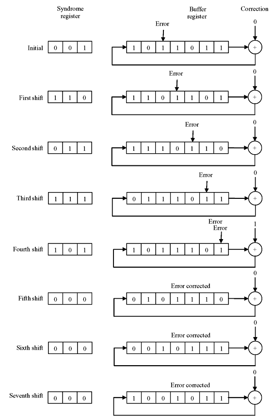
Figure 6.9 Sequence of Operation of Registers for Received Code 1011011 with Error
Decoding of cyclic code may be achieved by feeding the received vector from the right end to syndrome register. When r(x) is shifted from the right end as shown in Figure 6.10, the syndrome register contains sn – k(x) which is the syndrome of rn – k(x), the n – k cyclic shift of r(x). If sn – k(x) corresponds to error pattern e(x) with en – 1 = 1, the highest digit rn – 1 of r(x) is erroneous and is to be corrected. In rn – k(x), rn – 1 is at the location xn – k – 1. When rn – 1 is corrected, the error effect of sn – k(x) will be removed. The new syndrome is the sum of sn – k(x) and the remainder p(x) resulting from dividing xn – k – 1 by generator polynomial f(x). Since the degree of xn – k – 1 is less than the degree of f(x), p(x) = xn – k – 1. This implies that the error effect at the location xn – 1 can be removed by feeding the error digit from right end to the syndrome register through the exclusive OR gate as shown in Figure 6.10. The error correction and decoding process is identical to Figure 6.8. The schematic circuit for error correction and decoding of (7, 4) cyclic code for the generator polynomial f(x) = 1 + x + x3 is shown in Figure 6.11.
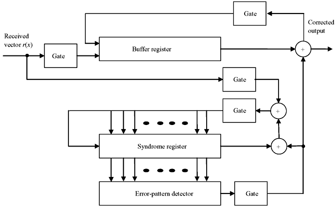
Figure 6.10 Error Correction when r(x) is Fed from Right End
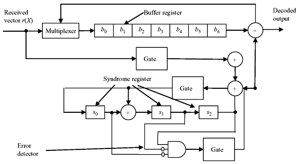
Figure 6.11 Error Correction for (7, 4) Cyclic Code with Generator Polynomial f(x) = 1 + x + x3 and r(x) is Fed from Right End
The error pattern and the syndrome register contents are shown in Table 6.5 when received data is fed through right end of syndrome register for generator polynomial f(x) = 1 + x + x3.
Table 6.5 Error Pattern and Syndrome Register for Generation Polynomial f(x) = 1 + x + x3.
Error Pattern e(x) |
Syndrome s(x) = Remainder of e(x)/f(x) s3(x) is three shifts of s(x)
|
Syndrome Vector
|
|---|---|---|
|
e(x) = x6 | s3(x) = 1 |
0 0 1
|
|
e(x) = x5 | s3(x) = x |
0 1 0
|
|
e(x) = x4 | s3(x) = 1 |
1 0 0
|
|
e(x) = x3 | s3(x) = 1 + x2 |
1 0 1
|
|
e(x) = x2 | s3(x) = 1 + x + x2 |
1 1 1
|
|
e(x) = x1 | s3(x) = x + x2 |
0 1 1
|
|
e(x) = x0 | s3(x) = 1 + x |
1 1 0
|
6.5 CYCLIC HAMMING CODE
A cyclic Hamming code of length 2m – 1 with m ≥ 3 can be generated in a cyclic form using the primitive polynomial p(x) of degree m. Dividing xm + i by generator polynomial p(x) for 0 ≤ i ≤ 2m – m – 1, we obtain
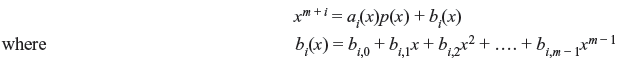
xm + i and p(x) are relatively prime as x is not a factor of p(x). Therefore, bi(x) ≠ 0 and consists of at least two terms. If bi(x) has one term say xj with 0 ≤ j ≤ m, then
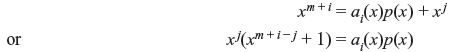
This implies that xm + i – j + 1 is completely divisible by p(x) which is impossible as m + i – j < 2m – 1 and p(x) is a primitive polynomial of degree m. Therefore, bi(x) consists of at least two terms. Other characteristic is that for i ≠ j, bi(x) ≠ bj(x).
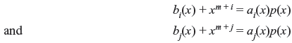
If bi(x) = bj(x), then combining the above two equations, we obtain
This implies that (xj – i + 1) is divisible by p(x), which is impossible. Hence, bi(x) ≠ bj(x). Therefore, cyclic Hamming code may be generated by the polynomial p(x). The matrix H = [Im Q] forms the parity-check matrix of the cyclic Hamming code as referred in Eq. (6.20). Im is an m × m identity matrix and Q is an m × (2m – m – 1) matrix formed with bi(x). The columns of Q has 2m – m – 1 elements of bi’s with 0 ≤ i ≤ 2m – m – 1. From above discussion, it is found that no two columns are similar and each column has at least two 1’s. Thus, H is the parity-check matrix of a Hamming code.
Decoding of Hamming code can be devised with schematic circuit shown in Figure 6.12. The received vector is fed to the syndrome register from right end. When all the data of a block is received, the syndrome register contents is equivalent to the remainder resulting from dividing xmxn – 2 (n = 2m) by generator polynomial p(x). The syndrome will be of the form of s(x) = xm – 1. Therefore, if any single error occurs at highest position, the syndrome will be (0000...01). For any single error at any other position, syndrome will be different from (0000...01). Hence, only a single multi-input AND gate is needed to detect the syndrome, where the highest location content of the AND gate is connected directly whereas rest of the contents are complemented.
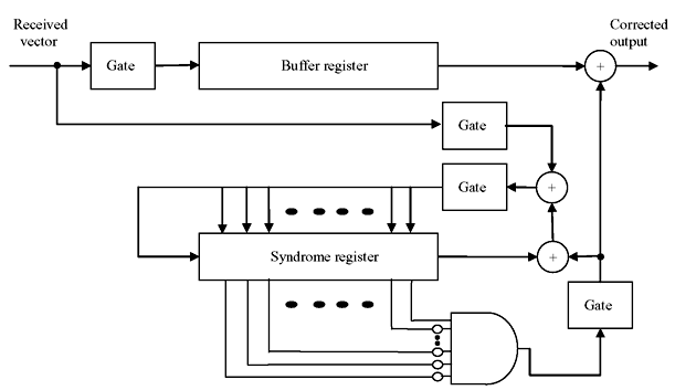
Figure 6.12 Decoding Scheme of Hamming Code
6.6 SHORTENED CYCLIC CODE
In a system, if a code of suitable natural length or of suitable number of information digits is not found, it may be desired to shorten a code to meet the requirements. Consider that in an (n, k) cyclic code C there is set of code vectors for which l numbers of leading locations are identical to zeros. There are 2k – l code vectors that form a part of the linear subcode of C. If l numbers of zero information digits are deleted from each of these code vectors, we obtain 2k – l set of vectors of length n – l. These 2k – l shortened vectors form an (n – l, k – l) linear code. This code is called shortened cyclic code or polynomial code. It is not cyclic. The shortened cyclic code has at least the same error-correction capability as the code from which it is derived.
The encoding and decoding with shortened cyclic code can be accomplished with the similar circuits as those of original cyclic code. However, at decoding end, the contents of syndrome register is critically shifted l times to generate proper syndrome. For large l, these extra l shifts of syndrome register cause unnecessary delay which can be eliminated by modifying either the connections of syndrome register or error-pattern circuit. Figure 6.13 exhibits a typical circuit schematic for decoding of (31, 26) shortened cyclic code shortened to (28, 23) with generator polynomial f(x) = 1 + x2 + x5.
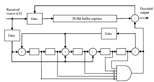
Figure 6.13 Decoding of Shortened Cyclic Code
6.7 GOLAY CODE
The binary form of the Golay code is one of the most important types of linear binary block codes. It is of particular significance since it is one of only a few examples of a nontrivial perfect code. A t-error-correcting code can correct a maximum of t errors. A perfect t-error-correcting code has the property that every word lies within a distance of t to exactly one code word. Equivalently, the code has minimum distance of 2t + 1. If there is an (n, k) code with an alphabet of q elements and a minimum distance of 2t + 1, then for M codewords,
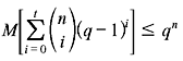
The above inequality is known as the Hamming bound. Clearly, a code is perfect precisely when it attains equality in the Hamming bound. Two Golay codes do attain equality, making them perfect codes: The (23, 12) binary code with minimum distance of 7, and the (11, 6) ternary code with minimum distance of 5. The (23, 12) binary Golay code can correct up to three errors.
This (23, 12) Golay code can be generated either by
or
Both polynomials f1(x) and f2(x) are factors of x23 + 1 and x23 + 1 = (1 + x)f1(x)f2(x). Several different ways are available to decode the (23, 12) binary Golay code that maximizes its error-correcting capability.
Extended Golay Code—Codes can be easily extended by adding an overall parity-check to the end of each code word. The (23, 12) Golay code can be extended by adding an overall parity check to each code word to form the (24, 12) extended Golay code.
6.8 ERROR-TRAPPING DECODING
Error-trapping decoding is a practical variation of Meggitt decoding devised by Kasami, Mitchell, and Rudolph. This decoding technique is most effective for decoding single-error-correcting codes, for some sort of double-error-correcting codes, and particularly for burst-error-correcting codes. Consider an (n, k) cyclic code with generator polynomial g(x) and code vector v(x) be transmitted and corrupted by the error pattern e(x). The received polynomial is r(x) = v(x) + e(x). The syndrome s(x) computed from r(x) is equal to the remainder resulting from dividing error pattern e(x) by generator g(x), i.e., e(x) = a(x)g(x) + s(x). If the error is confined to n – k high-order positions, then e(x) = ekxk + ek + 1xk + 1 + ... + en – 1xn – 1. Now, if r(x) is cyclically shifted by n – k times the error will be confined to n – k low order parity positions and the error pattern will be

Since the degree of e(n – k) (x) is less than n – k and syndrome s(n – k) (x) of r(n – k)(x) is obtained from the remainder while dividing e(n – k) (x) by g(x), we observe the following equality:

Multiplying both sides by xk, we have

This means, if errors are confined to the n – k high order positions of received polynomial r(x), the error pattern e(x) is identical to xks(n – k) (x), where s(n – k) (x) is the syndrome of r(n – k) (x), the (n – k)th cyclic shift of r(x). Therefore, the transmitted code vector can be obtained by computing s(n – k) (x) and addition of xks(n – k) (x) to r(x).
Now consider that burst error has occurred at (n – k) consecutive positions of r(x), starting from ith position, but not confined to (n – k) high-order positions. If r(x) is cyclically shifted to right by (n – i) times, the errors will be confined to (n – k) lower order position of r(n – i) (x) , i.e., r(x) with (n – i) right shifts, and the error pattern is identical to xis(n – i) (x), where s(n – i) (x) is the syndrome of r(n – i) (x).
If polynomial r(x) is received through syndrome register from right end and shifted, it makes equivalent to pre-multiplication of r(x) by x(n – k). The contents of syndrome register form the syndrome s(n – k) (x) of r(n – k) (x) after entire r(x) is shifted into syndrome register. If errors occur at (n – k) high-order positions, they are identical to s(n – i) (x). However, if errors are confined to (n – k) consecutive positions other than (n – k) high-order positions, the syndrome register must be further shifted for certain number of times before its contents are identical to the error digits. This shifting of syndrome register is called error trapping. Now the error correction can be accomplished by simply adding the contents of syndrome register to the received vector. For t-error-correcting code, the weight of the syndrome register may be tested after each shift. As soon as the weight of the syndrome becomes t or less, it may be assumed that errors are trapped in the syndrome register. For t or fewer errors confined to (n – k) consecutive positions, the error pattern will be of the form e(x) = xjB(x), where B(x) has t or fewer terms and has degree n – k – 1 or less. For end-around case, same form may be obtained after certain cyclic shift of e(x). Dividing e(x) by generator polynomial g(x), we have
where s(x) is the syndrome of xjB(x). As s(x) + xj B(x) is a multiple of g(x), it is a code polynomial. If the weight of s(x) is t or less and s(x) ≠ xj B(x), then s(x) + xj B(x) is a nonzero code vector with weight less than 2t + 1. But t-error-correcting code must have the minimum weight of 2t + 1. Therefore, it may be concluded that errors are trapped in syndrome register only when the weight of the syndrome becomes t or less and s(x) = xj B(x).
Based on the discussions above, the error-trapping decoder may be implemented as shown in the schematic diagram of Figure 6.14. The polynomial r(x) is received in syndrome register shifting through right end, as well as in k-bit buffer register, as only k bits of information are required to be analyzed. After receiving entire r(x) in the syndrome register, the weights of its contents are tested by an (n – k) input threshold gate. The output of threshold gate is 1 when t or fewer inputs are 1. If the weight of the syndrome is t or less, the contents of syndrome register are identical to the error digits at (n – k) high-order positions of r(x).
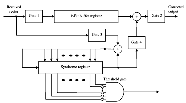
Figure 6.14 Schematic of Error Trapping Decoder
In case of the error not confined to (n – k) high-order positions, cyclically shift the syndrome register once, keeping gate3 on and all other gates at off condition. If weight of the new syndrome is tested to be t or less, the errors are confined to the locations xk – 1, xk, ..., xn – 2 of r(x) and contents of syndrome register are identical to errors at these locations. Therefore, the received digit rn – 1 is error-free and read out from buffer register. If the weight of the syndrome is greater than t, the syndrome register is shifted once more and tested as described previously.
Thus, syndrome register is shifted continuously until the weights of its contents go down to t or less. If the weight becomes t or less after ith shift, the contents of buffer register are error-free and read out of the buffer register, the contents of syndrome register are shifted out and used to correct next n – k received digits. Any nonzero digits left in the syndrome register are ignored as they are the parity parts.
Implementation of error-trapping decoder is possible in a different manner as shown in schematic diagram of Figure 6.15. In this scheme the error patterns confined to n – k consecutive end-around locations can be corrected in a faster way. Here the received vector is shifted from left into the syndrome register. If the errors are confined to n – k low-order parity positions of r(x), then, after entire r(x) is entered in the syndrome register, the contents of syndrome register are identical to error digits of similar positions of r(x). And if errors are not confined to n – k low-order parity positions of r(x), but are confined to n – k consecutive locations, after n – i cyclic shifts of r(x), errors will be shifted to the n – k low-order positions of r(n – i) (x). The syndrome of r(n – i) (x) will be identical to the errors confined to the positions xi, xi + 1, ..., x(n – k) + i – 1 of r(x).
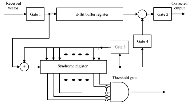
Figure 6.15 Error Trapping Decoder
The decoding of cyclic Hamming code as described earlier is actually an error-trapping decoding. Error-trapping decoding is most effective for single or burst error correction. However, this decoding technique is ineffective for long and high rate codes with large error-correcting capability.
6.8.1 Improved Error-trapping
The error-trapping decoding as described above may be further improved with additional circuitry if most errors are confined to n – k consecutive locations and fewer errors are outside the n – k digits span. An improvement proposed by Kasami is discussed here.
The error pattern e(x) of received vector r(x) may be divided into two parts: eP(x), errors at parity section, and eI(x), errors at information section.

Dividing eI(x) by generator polynomial g(x), we have
The remainder p(x) is of the degree of n – k – 1 or less. Therefore,

As eI(x) has the degree of n – k – 1 or less, p(x) + eP(x) must be the remainder resulting from dividing the error pattern e(x) by the generator polynomial. Hence, p(x) + eP(x) is equal to the syndrome of received vector r(x).
or
Thus, if error pattern of information part ei(x) is known, the error pattern of parity part eP(x) can be found.
The improved error-trapping decoding technique as devised by Kasami requires searching a set of polynomials ![]() of degree k – 1, such that, for any correctable error pattern e(x) there exists one polynomial Φj(x). This implies that xn – kΦj(x) matches the information part of e(x) or cyclic shift of e(x).The polynomials Φj(x)’s are called covering polynomials. The decoding procedure is described as follows:
of degree k – 1, such that, for any correctable error pattern e(x) there exists one polynomial Φj(x). This implies that xn – kΦj(x) matches the information part of e(x) or cyclic shift of e(x).The polynomials Φj(x)’s are called covering polynomials. The decoding procedure is described as follows:
- The received vector is entirely shifted into syndrome register.
- Weight of s(x) + pj(x) is calculated for each j = 1, 2, ..., N, where pj(x) is the remainder resulting from dividing xn – kΦj(x) by the generator polynomial g(x).
- If, for some m, [the weight of s(x) + pm(x)] ≤ [t – weight of Φm(x)], then xn – kΦj(x) matches the error pattern in the information part of e(x) and s(x) + pm(x) matches the error pattern in parity part. Hence, e(x) = s(x) + pm(x) + xn – kΦm(x). Correction may be done by taking modulo-2 sum of r(x) + e(x). In this step, N(n – k)-input threshold gates are required to test the weights of s(x) + pj(x) for j = 1, 2, ..., N.
- If [the weight of s(x) + pj(x)] > [t – weight of Φj(x)] for all j = 1, 2, ..., N, both the buffer and syndrome registers are shifted cyclically once. The weights of new contents of syndrome register and pj(x) is again tested as above.
- The syndrome and buffer registers are continuously and cyclically shifted till the condition [the weight of s(i)(x) + pm(x)] ≤ [t – weight of Φm(x)] is not fulfilled, s(i)(x) being the ith shift of s(x).
- If the above condition never arises, the error pattern is uncorrectable.
This error-trapping method is applicable to many double-error-correcting and triple-error-correcting codes. It is applicable to relatively short and low rate codes. For longer code length, its complexity increases, as the number of covering polynomials N is required to be more, as well as N(n – k)-input threshold gate is required.
6.9 MAJORITY LOGIC DECODING
Majority logic decoding scheme is an effective method of decoding certain classes of block codes especially certain cyclic codes. It was first devised by Reed for a class of multiple-error-correcting codes and its algorithm is later extended and generalized by many investigators. First such generalization was performed by Massey.
Let us consider an (n, k) cyclic code c with parity-check matrix H. The row space of H is an (n, n – k) cyclic code denoted by Cd which is a dual code of C. For any vector V in C and W in Cd, the inner product of V and W is zero, i.e.,

In fact there exists a code vector in c, if and only if W · V = 0, where V is the vector in Cd. The equality of Eq. (6.36) is called parity-check equation and there are 2n – k such parity-check equations.
If code vector V is transmitted and received vector is R with error vector E, then R = V + E. For any vector W in dual code Cd, the parity-check sum or check sum may be formed with linear sum of the received digits as follows:

If R is a code vector, A must be zero. In case of error,
As W · V = 0, A = W · E,
or

An error digit Ei is assumed to be checked by check sum A, if Wi = 1. Suppose there exists J numbers of vectors in the dual code Cd. Then we have the following sets of relations:
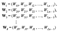
These J vector are orthogonal on the (n – 1)th position and said to be orthogonal vectors. This set of equations has the following properties:
- The (n – 1)th component of each vector is ‘1’, i.e.,
W1,n – 1 = W2,n – 1 = W3,n – 1 = ... = Wj,n – 1 = 1
- For i ≠ n – 1, there exists at most one vector whose ith component is “1”, i.e., if W1,i = 1, then
W2,i = W3,i = ... = WJ,i = 0
Using these properties, the following equations may be formed with J orthogonal vectors and Eq. (6.38).
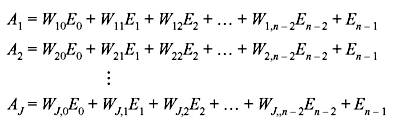
These J check sums are said to be orthogonal on error digit En–1. Since Wi,j = 0 or 1, the check sum equations can be generalized in the form:

If all error digits in check sum AJ are zero for i ≠ n – 1, then AJ = En–1. Based on this fact, En–1 or the received digit Rn–1 can be estimated. Suppose there are at most [J/2] errors in the error vector E, i.e., [J/2] or fewer components of E are 1. If En–1 is 1, the other nonzero errors are distributed among at most [J/2] – 1 check sums orthogonal on En–1. Hence, at least [J/2] + 1, or more than one-half of the check sums orthogonal on En – 1 have En – 1 = 1. On the other hand, if En – 1 is 0, the other nonzero errors are distributed among at most [J/2] check sums. Therefore, at least [J/2] or one-half of the check sums orthogonal on En – 1 have En – 1 = 0. Hence, the value of En – 1 is equal to the value assumed by clear majority of the parity-check sums orthogonal on En–1. If no value is assumed by clear majority of the parity-check sum, i.e., in case of tie, the error digit En – 1 = 0. Hence, an algorithm for decoding En – 1 may be formulated as: The error digit En – 1 is decoded as 1, if a clear majority of the check sums orthogonal on En – 1 is 1, otherwise En – 1 is decoded as 0.
If there are [J/2] or fewer errors are present in error vector E, correct decoding of En – 1 is guaranteed and it is possible to form J parity-check sums orthogonal on any error digit because of the symmetry in cyclic code, which is identical to decoding of En – 1. It may further be noted that a cyclic code with minimum distance dmin is said to be completely orthogonalizable in one step, if and only if it is possible to form J = dmin –1 parity-check sums orthogonal on an error digit. A general schematic diagram of majority logic decoding is shown in Figure 6.16.
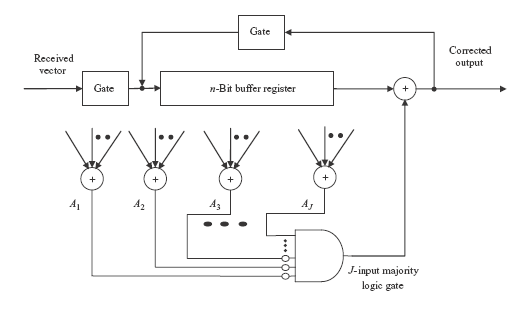
Figure 6.16 Majority Logic Decoder
6.10 CYCLIC REDUNDANCY CHECK
A cyclic redundancy check (CRC) is an error-detecting code whose algorithm is based on cyclic codes. It designed to detect accidental changes to raw computer data, and is commonly used in digital networks and storage devices such as hard disk drives. Blocks of data entering these systems get a short check value attached, derived from the remainder of a polynomial division of their contents; on retrieval the calculation is repeated, and corrective action can be taken against presumed data corruption if the check values do not match.
If m(x) is the message polynomial and g(x) is generator polynomial, then m(x) = q(x)g(x) + r(x), where q(x) and r(x) are the quotient and remainder, respectively. Transmitted data will be m(x) + r(x). If g(x) is chosen to be of k bits, the remainder must be of k – 1 bits. Message polynomial m(x) is initially formed with original message followed by k – 1 numbers of zeros. The cyclic redundancy check is formed by the remainder polynomial r(x). The receiver repeats the calculation, verifying the received and computed r(x). If they are equal, then the receiver assumes the received message bits are correct.
Example 6.8: Suppose there is the message data 11010011101100 is to be transmitted, where g(x) = 1011. As g(x) is of four bits, the remainder must be of three bits.
The message polynomial is formed by inserting three 0s at the end, as m(x) = 11010011101100 000. Now with the long division operation we have the remainder as r(x) = 100. Therefore, the transmitted coded message will be m(x) + r(x), i.e., 11010011101100 000 + 100 = 11010011101100100.
The validity of a received message can easily be verified by performing the above calculation again. The received data 11010011101100100 is divided by g(x), i.e., 1011. The remainder should be equal to zero if there are no detectable errors.
CRCs are specifically designed to protect against common types of errors on communication channels, where they can provide quick and reasonable assurance of the integrity of messages delivered. However, they are not suitable for protecting against intentional alteration of data. First, as there is no authentication, an attacker can edit a message and recalculate the CRC without the substitution being detected. Second, the linear properties of CRC codes even allow an attacker to modify a message in such a way as to leave the check value unchanged and otherwise permit efficient recalculation of the CRC for compact changes.
The design of the CRC polynomial depends on the maximum total length of the block to be protected (data + CRC bits), the desired error-protection features, and the type of resources for implementing the CRC as well as the desired performance. The generator polynomial must be chosen to maximize the error-detecting capabilities while minimizing overall collision probabilities. Typically, an n-bit CRC, applied to a data block of arbitrary length, will detect any single error burst not longer than n bits, and will detect a fraction 1 – 2 –n of all longer error bursts.
6.11 SOLVED PROBLEMS
Problem 6.1: If g(x) = 1 + x + x3 for a (7, 4) cyclic code, then find the code vector for the message u = (1010).
Solution: For (7, 4) cyclic code, the polynomial 1 + x7 can be factorized as
For generator polynomial g(x) = 1 + x + x3, the minimum distance is 3 of single-error-correction capability. The message word u = (1010) is equivalent to u(x) = 1 + x2. The code vector is g(x) · u(x) = (1 + x + x3)(1 + x2) = 1 + x + x2 + x5 or (1110010).
Problem 6.2: Consider g(x) = 1 + x + x3 for a (7, 4) cyclic code. Find the generator matrix of systematic form.
Solution: Dividing x3, x4, x5 and x6 by g(x), we have
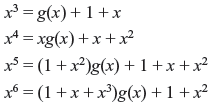
Rearranging the above equations, we have
Considering above equations in matrix form, we obtain the generator matrix of order of (4 × 7) in systematic form in cyclic code.
Problem 6.3: Let the generator polynomial is g(x) = 1 + x + x2 + x4 + x5 + x8 + x10 of cyclic code over GF(2) with block length of 15. Find the parity-check matrix H. How many errors can be detected by this code? How many errors can be corrected by this code? Write the generator matrix in systematic form. Find the generator polynomial of its dual code.
Code vectors generated by x5h(x –1) = 1 + x2 + x4 + x5 have the minimum distance of 5 and are capable of correcting any single error as well as detecting combinations of double error.
The generator matrix in systematic form can be obtained from dividing xn – k – i by generator polynomial g(x) for i = 0, 1, 2, ..., k – 1, such that
where bi(x) is remainder of the form of

Since xn – k – i + bi(x) is the multiple of g(x) for i = 0, 1, 2, ..., k – 1, they are code polynomials and generator matrix for systematic form may be arranged in k × n matrix form as
and corresponding parity matrix is
Problem 6.4: Consider the decoding of a (7, 4) cyclic code generated by g(x) = 1 + x + x3. The code has minimum distance of 3 and capable of correcting any single error over the block length of 7. Draw the schematic diagram of the syndrome circuit and find out the register contents after seventh shift for a received vector of 0010110.
Solution: The schematic of syndrome circuit is given in Figure 6.17. The syndrome register contents for each shift are given in Table 6.6.
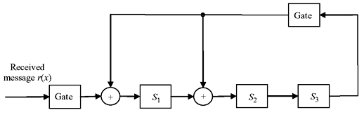
Figure 6.17 Syndrome Computing Circuit
Table 6.6 Syndrome Register Contents
|
Shift |
Input |
Register Contents |
|---|---|---|
|
|
|
0 0 0 Initial state |
|
1 |
0 |
0 0 0 |
|
2 |
1 |
1 0 0 |
|
3 |
1 |
1 1 0 |
|
4 |
0 |
0 1 1 |
|
5 |
1 |
0 1 1 |
|
6 |
0 |
1 1 1 |
|
7 |
0 |
1 0 1 s0 |
|
8 |
– |
1 0 0 s1 |
|
9 |
– |
0 1 0 s2 |
MULTIPLE CHOICE QUESTIONS
- For a (7, 4) cyclic code generated by g(x) = 1 + x + x3 the syndrome of error pattern e(x) = x3 is
- 101
- 110
- 111
- 011
Ans. (b)
- For generator polynomial g(x) = 1 + x2 + x3 of a (7, 4) cyclic code the message word u = (1010). The code vector is
- 1010101
- 1001001
- 1001110
- 1100011
Ans. (c)
- The generator polynomial of cyclic code of block length n is a factor of
- 1 + xn
- 1 + xn + 1
- 1 + xn + 2
- 1 + xn – 1
Ans. (a)
- The generator polynomial of a (7, 4) cyclic code has the degree of
- 2
- 3
- 4
- 5
Ans. (b)
- If C is a code word and H is the parity-check matrix, then for a valid and correctly received code word
- CH = 0
- CTH = 0
- CTHT = 0
- CHT = 0
Ans. (d)
- The syndrome polynomial in a cyclic code solely depends on
- generator polynomial
- parity polynomial
- error polynomial
- code word
Ans. (c)
- What is the minimum distance for a (31, 21) code?
- 3
- 4
- 5
- 6
Ans. (c)
REVIEW QUESTIONS
- What do you mean by Cyclic Burst?
- What are the degree of polynomials for (7, 4), (15, 8) and (31, 16) cyclic codes?
- Show that the generator polynomial g(x) = 1 + x2 + x4 + x6 + x7 + x10 generates a (21, 11) cyclic code. Develop a decoder circuit for it. If the received polynomial is r(x) = 1 + x5 + x17, compute the syndrome for it.
- Consider g(x) is the generator polynomial of binary cyclic code of block length n.
- Show that, if 1 + x is one of the factors of g(x), the code contains the code vectors of all even weights.
- If n is odd and 1 + x is not the factor of g(x), show that one of the code vector contains all 1’s.
- If n is the smallest integer such that g(x) divides xn + 1, show that the code has the minimum weight of at least 3.
- Consider generator polynomial g(x) = 1 + x + x3. Find the encoding circuit and complete the code vector for the massage vector u(x) = c
- Consider a systematic (8, 4) code whose parity-check equations are v0 = u1 + u2 + u3, v1 = u0 + u1 + u2, v2 = u0 + u1 + u3 and v3 = u0 + u2 + u3. Find the generator matrix and parity-check matrix for the code. Show that the minimum distance of the code is 4.
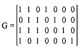
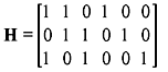
- Determine whether the received code (111011) is a valid code when the parity-check matrix is
- Shorten the (31, 26) cyclic Hamming code by deleting 11 high order message digits to form (20, 15) shorten cyclic code. Devise a decoder circuit for this.
- Devise an encoder and a decoder circuits for (15, 11) cyclic code generated by the generator polynomial g(x) = 1 + x + x4.
- Consider two cyclic codes c1 and c2 of block length n generated by generators g1(x) and g2(x), respectively. Show that the code polynomials common to both c1 and c2 also forms a cyclic code c3. Determine the generator polynomial for c3. If d1 and d2 are the minimum distances of c1 and c2, respectively, find the minimum distance of c3.