
Most people are pretty familiar with the “cat chasing the little red dot” paradigm. It’s so popular it even had a short scene in one of the Shrek movies. Some cats will chase the laser spot until they drop. Some will only chase it for a little while. In any event, anyone who has a cat has probably used a laser pointer when playing with their feline friend at some point.
But wouldn’t it be nice if you could entertain your cat when you’re not there? A laser pointer, contrary to what you might think, does not have to be held and controlled by a human. With a little programming and mechanical engineering magic, you can have yourself an autonomous cat toy.
However, in the cat-toy project we’ll build in this chapter, we won’t leave it at that. We just can’t. After all, it wouldn’t make sense to have the toy always moving, whether your cat is around to play with it or not, would it? So, we’ll add something special—an infrared sensor. That way, it’ll turn on only when your cat’s around, and it will turn off when the cat leaves the room.
Are you ready? Let’s start by getting the parts we’ll need to create our cat toy.
A Shopping List of Parts
A Raspberry Pi
Two standard (not continuous) servos—I recommend the Parallax 900-00005 ( http://www.parallax.com/product/900-00005 ), but any model will work
A cheap laser pointer, which you can purchase at a pet store for around $10 US (see Figure 9-1)
A PIR motion sensor ( http://parallax.com/product/910-28027 )
Glue/epoxy
Miscellaneous wires (red, black, and so forth)
Flat-headed screw
Electrical tape
Popsicle stick
9V battery
A container on which to mount everything—I used a short length of PVC pipe

An ordinary laser pointer used with the cat toy
The Concept Behind the Toy
The key to making this toy work is random motion . If you program the toy to make a series of concentric circles, one after another, and then repeat the pattern, it won’t take long for your cat to recognize the pattern and get bored. However, by using Python’s random or randint functions, you can randomize the patterns and keep your cat (and possibly your toddler) entertained.
Another thing to keep in mind is that you will be randomizing the motion on two axes—the x-axis and the y-axis—while keeping the motion within certain bounds (which is where the parameters of the randomizing functions and the movement extremes of the servos come in). You will be using two servos, but they’ll be joined together so as to control the motion of one laser pointer. To control the servos, like in several other projects in this book, we’ll use the Pi’s GPIO pins and Python’s GPIO library. Another nice thing about this project is that the servos end up drawing so little power that they can be sourced with a simple 9V battery. You still need to power them separately from the Pi (always a good idea, regardless of the project), but you don’t need a fancy battery setup as you do with many other projects.
Creating and Using Random Numbers
You’d think creating and using random numbers would be simple. Just call a function, get a random integer, and proceed. While that may be how it works in practice and is all that most of us think of, the actual process of randomizing output is fascinating—it’s actually the subject of intense study by many computer scientists and mathematicians. (See the sidebar “Oh, the Randomness.”) To get a random number in Python, you can use several built-in functions. The first is, appropriately enough, the random() function. This function returns a float (a floating point decimal number). It takes no parameters, returning instead a random number between 0.0 and 1.0. This is often very useful, but for our purposes we’re going to need somewhat larger numbers, preferably in an integer format, which can be done with the randint() function.
Oh, the Randomness
Since ancient times, humans have had many methods for generating “random” numbers, from flipping a coin, to rolling a die, to shuffling a deck of cards. And for most applications, any of these would be fine. If you need to decide who kicks the ball first, you can flip a coin; choosing one card out of a deck of 52 is random enough to make it very impressive when a magician successfully guesses its identity.
However, there are two main issues with using these methods to generate random numbers for any true mathematical or statistical endeavor. First of all, they are all based on physical systems—the flip of a round coin in the air, the rolling of a more-or-less square die on a not-so-level patch of ground. Because they are physical systems, they can never be truly random. Given enough iterations, a pattern will eventually start to emerge based on imperfections in the system. A coin, for example, has a slight weight bias on one side due to the patterns engraved on both faces. If you flip it enough times, that pattern will show itself in the collected results. It may take several million or several billion flips, but it will emerge. Likewise, a die will never be perfectly square or perfectly weighted and will eventually show a bias toward one side after a sufficient number of rolls.
The second issue with these methods of generating random numbers is simply that they take too much time. If you need a good batch of a million random numbers, you’re going to be flipping a coin for a long time to get all those numbers. It’s just impractical for large batches of data.
But computers are excellent at handling immense batches of numbers and data, and they can generate them incredibly fast. The average desktop computer can process at a theoretical speed of around 7 Gigaflops. (That’s 7 billion floating-point operations per second.) At that speed, generating a million random numbers would take . . . well, let’s see . . . carry the two . . . divide by yellow. . . um . . . about 7 milliseconds. Much faster than card shuffling.
However, computers, again, are physical systems. Yes, you’re generating the numbers from within the “cyberspace” of the computer’s central processor, but that processor is a physical silicon chip with physical transistors and wires. No matter what program you use to generate those random numbers, they will eventually display a pattern that shows they are not truly random. Thus, you see the interest in random numbers by mathematicians and scientists. A truly random number generator would be incredibly useful in many areas of science, not the least of which is cryptography. Most ciphers are based on a random hash code; a truly random code would be infinitely more difficult to crack, which is one of the reasons for the intense interest.
Current random-number generators work by using algorithms that create long strings of pseudo-random numbers, often based on combinations of multiplications and modulus operations. Depending on the quality of the algorithm, the numbers thus generated may or may not be cryptographically sound, though they are most often random enough for applications such as video games. In other words, the algorithm you use to generate random numbers probably won’t stop a concerted effort to crack the code by a supercomputer, but it’s good enough to generate opponents when you play Call of Duty: The Day We All Died at the Hands of the Sixth-Grader Down the Block.
This generation process is why, when you begin a program that will be using random numbers, you have to “seed” the random-number generator with another number, such as today’s date or the system time on your computer. The random seed is simply a number used to initialize the random-number vector algorithm in the program. So long as the original seed is ignored, subsequent initializations should provide sufficiently random numbers. Yes, eventually a pattern will emerge—it’s inevitable—but a randomly seeded generator should be sufficiently random for most needs, particularly a random-motion cat toy. Schrödinger’s cat might not be fooled, but your feline should be. (Sorry—just a little physics humor there.)
According to the Python docs, randint(a, b) returns a random number n, such that n is between a and b, inclusive. In other words, the following code
should return 1, 2, 3, 4, 5, 6, 7, 8, 9, or 10. We’re going to use it to generate positions for the servos we use.
Note
The Python docs can be found at http://docs.python.org . I highly recommend that, as you learn the language, you get in the habit of consulting the docs. You can also type help(function) at the interactive Python prompt to get the same reading material.
Using the GPIO Library
Now that you have an idea of how we’re going to generate our random numbers, you need to know how to control the servos that will be attached to the Pi. Luckily, there is a Python library that is specifically designed for this purpose and comes preinstalled on the Pi. This library enables us to access the Pi’s General Purpose Input Output (GPIO) pins and is called, simply, RPi.GPIO.
You may have to manually install the Python development libraries if you haven’t done so already. First, make sure your Pi is up to date by typing
and then install the packages by typing
We can now start typing our final code for this project. Remember, it’s available as cat-toy.py from Apress. com . Now, to access the Pi, call the following in the first lines of your program:
Then, configure it by typing

Pinout of GPIO pins
Note
Keep in mind that with GPIO.setmode(GPIO.BOARD), when you refer to pin 11, you’re actually referring to the physical pin #11, which translates to GPIO17 in the diagram in Figure 9-2), not GPIO11, which translates to the physical pin #23).
Once you set the mode, you can then set each pin to be either an input or an output. Users of the Arduino will probably recognize the concept here, but this is what you type for the Pi:
and so forth. Once you set a pin as an output, you can then send voltage to it (turn it on) by entering
or
Subsequently, you can turn it off by entering
or
We’ll use two pins for servo controls, one pin to power the laser pointer, and another to read input from the IR sensor.
Controlling the Servo
Servos are an important part of many different applications, from radio-controlled vehicles to high-end robotics. A servo is, at its heart, nothing more than a DC motor. However, with the help of software you can have extremely fine control over the motor’s rotation. For example, if you need it to rotate 27.5 degrees and then stop (and assuming the servo is capable), you can send it that command programmatically.
So, how do you do that using the GPIO pins on the Pi? Unfortunately, you can’t just plug the servo’s signal wire (the white one, usually) into a GPIO out pin, give it a positive and negative voltage, and expect it to work. It may, but then again it may not.
The answer lies in how to control servos. As analog pieces of hardware, they predate most of today’s digital hardware, including the Pi. They operate using pulse-width modulation (PWM) signals. To control them, you must be able to send PWM signals via whatever mechanism you’re using, whether it’s an Arduino pin, serial cable, or Raspberry Pi’s GPIO pin. If you want to set a servo’s position, you need to send it regular pulses of current—50 times a second is an average pulse speed—rather than one long pulse. That 50 times a second translates—if you’re wondering—to one pulse every 20 milliseconds (ms).
The length of that pulse, moreover, is what determines the position of the servo. An on pulse of 1.5ms, for example, sent every 20 milliseconds, will send the servo to the center position. Shorter pulses will turn it one direction, while longer pulses will send it the other. Thus, by precisely timing the length of the pulses you send to the servo, you can precisely position the servo head.
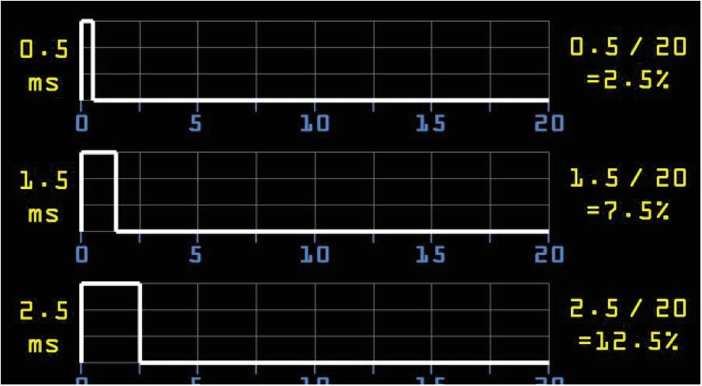
Duty cycles of a servo
If you want to send the servo to the neutral “zero” position, you send it a 1.5ms on pulse every 20 milliseconds, which can be thought of as a duty cycle of 7.5 percent. Likewise, if you want to turn it counterclockwise with a 0.5ms on pulse, it has a duty cycle of 2.5 percent, and a longer 2.5ms on pulse translates to a 12.5 percent duty cycle. In other words, the servo is given a “high” pulse 2.5 percent, 7.5 percent, or 12.5 percent of the time.
These directions are applicable to standard—not continuous—servos. The difference is that while standard servos use the length of the pulse to determine their final position (in degrees from center), continuous servos use the length of the pulse to determine the speed at which they should turn. A standard servo will move to its destination position and then stop until a new command is sent; a continuous servo is almost always moving, with the speed of the movement determined by the pulse lengths. And while you could conceivably use either type of servo for the cat toy, it makes more sense to use standard servos and thus have both the capability of exact positioning and the ability to stop completely, allowing the cat to—temporarily, at least—“catch” the little red dot.
The problem with this method of moving servos, however, is that it can be difficult to use the Pi and Python to send millisecond-length pulses to the GPIO pins. Like all other processes running on the Pi, Python is constantly being interrupted by system-level running processes, making the precise timing of pulses by a Python program impractical, to say the least. However, once again, the GPIO library has what we need: you can use the library to set a GPIO pin as a PWM pin, giving it the duty cycle necessary to send the correct-length pulses to the pin.
So, while it is theoretically possible to script something like this:
the results would most likely be something completely unexpected, if it worked at all. Instead, what we can do is use the RPi.GPIO library function to set the servo’s signal pin (pin 11 in our example case here) to be a PWM output pin by entering
The 50 in this case sets the pulses to 50Hz (one pulse every 20 milliseconds), which is what the servo requires to work. We can then set the pin’s duty cycle to 7.5 percent by typing
If we put p.start(7.5) inside a while loop, the result is that the servo will move to the center position and then remain there. Changing the duty cycle with p.ChangeDutyCycle() will allow us to move the servo in different directions, which is what we’re going for with the cat toy. So, for example, to see your servo move back and forth, try the following script:
Running this script should make your servo sweep back and forth, pausing for a second between each direction change.
All that’s left for our cat-toy script is to implement some random numbers. Those numbers will determine which servo moves, in which direction, and for how long. The result should be a rather random path in two dimensions.
Constructing the Servo Mechanism
Our cat toy is going to sweep a laser pointer in two directions, which means we need a servo capable of the same thing. While servos aren’t generally capable of two-dimensional motion, we can easily construct a pan-and-tilt servo mechanism using two normal servos attached to each other.
Note
This procedure will permanently bond your two servos, making them inseparable, so make sure you have others to use for other projects. However, remember that a pan-and-tilt setup like you’re making here is a handy thing to have for projects where you need to move an item in two dimensions, and you’ll probably use it again. So, it’s not like you’re trashing the two servos completely.
All you need to do is mount the body of one servo to the horns of the other. To make a secure connection, you may need to remove the screw holding the servo horns of the base servo (let’s call it the x-axis servo to keep the task simple) and file down the plastic a bit. You’re trying to flatten the top of the servo as much as possible to mate it tightly with the body of the other (y-axis) servo.
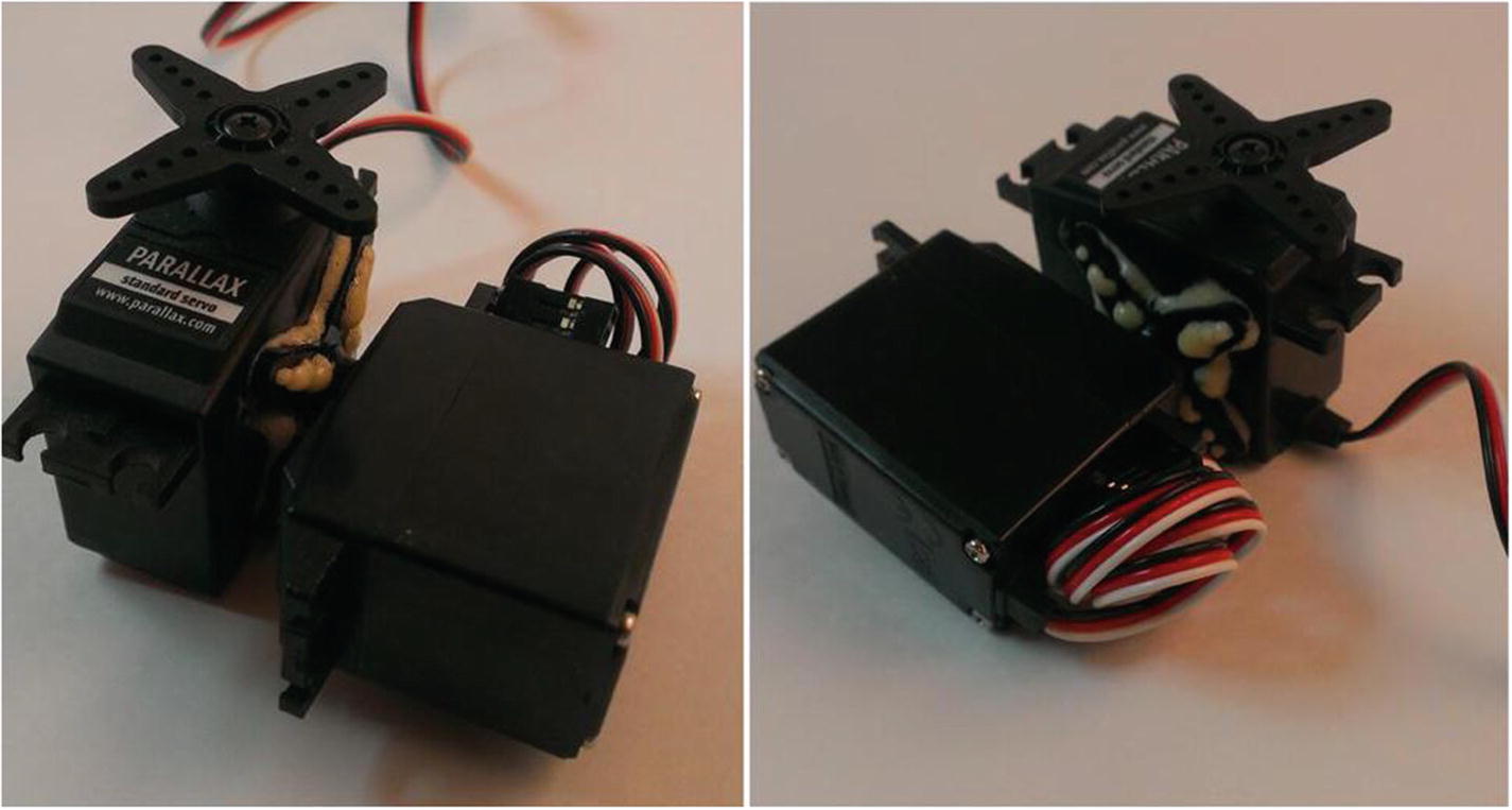
Bonded x and y servos
The laser pointer can now (after some not-so-minor modifications) be mounted to the top (y-axis) servo.
Constructing the Laser Mechanism
We’re going to use a standard laser pointer, but we’re going to modify it in a few important ways. The most important way is that instead of using batteries, we’ll power it using the Pi’s GPIO pins. This is important because it enables us to turn the laser on and off programmatically rather than by fussing with the push-button switch.
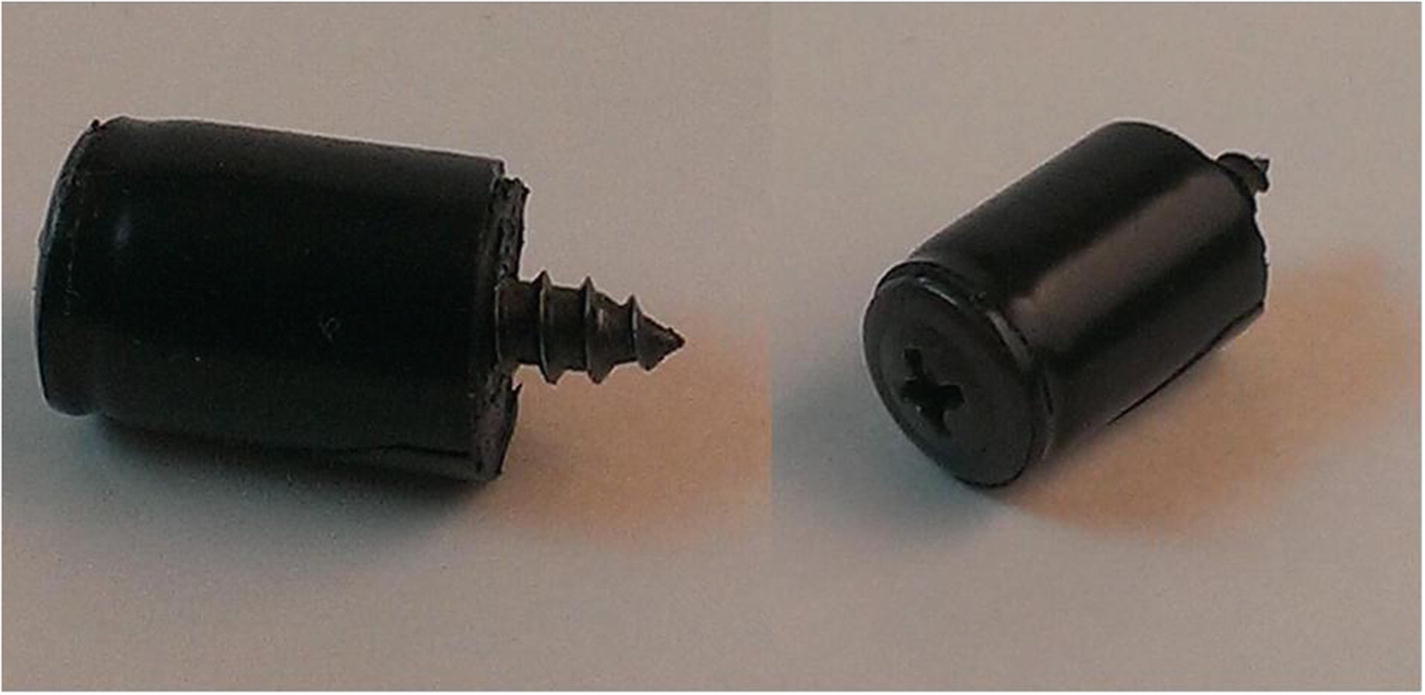
Screw mechanism for laser pointer
Remove the laser pointer’s base and take out the batteries. Push the screw, head first, into the body of the pointer so that the screw head is pushing down the inner spring that is normally held down by the batteries. You may have to play with the amount of tape you use to wrap the screw; you want it to be a tight-enough fit to press down the spring and stay in place without being in danger of moving.
We also need to tape the laser pointer’s power button down so that it’s always on. As I said, we’ll be taking care of powering the pointer from the Pi. Wrap a piece of tape around the pointer to hold down the button.

Completed laser-pointer mechanism
If you want to test your work (never a bad idea), use a few alligator clips to connect the screw’s point to pin #6 (the ground pin) on the Pi, and then connect the body of the pointer to pin #1 (3.3V). The laser should light, showing you are powering it directly from the Pi’s power pin. If nothing happens, make sure the screw head is pressing on the spring, the power button is securely taped down, and all your connections are solid. Once the connections are solid, you’re ready to mount the laser to your two-dimensional servo contraption.
Connecting the Laser to the Servo
Connecting the laser to the servo is probably the easiest part of the project. If you’re like me, you don’t want to permanently attach the laser to the pan-and-tilt servo setup you’ve got, because that setup can come in handy with other projects. So, we need to find a way to temporarily attach the laser to the servo horns.
I used a popsicle stick to pull this off. We can glue the laser to the popsicle stick, and then screw the stick to the servo horns. This can be done with either the screws that came with the servo (you still have them, don’t you?) or the smallest screws you can find in your workshop. Trust me—those are really tiny holes in the servo horn.
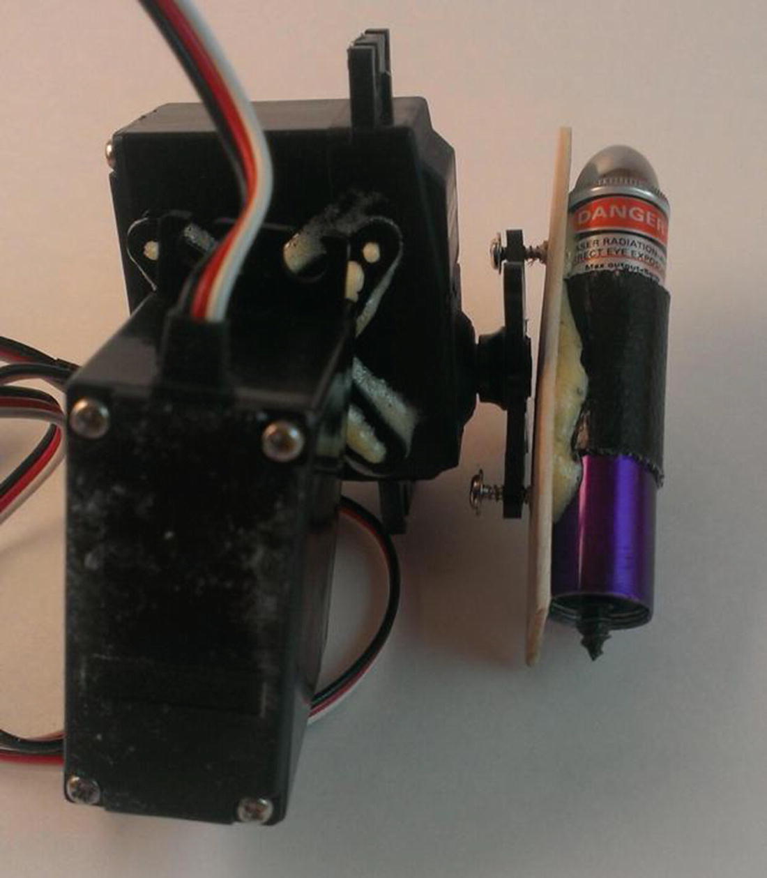
Laser mounted to servos
A word of caution here: take some time and position the laser pointer and its associated servo so that the laser can spin freely no matter where in the cycle the two servos are. Obviously, the easiest way to do this is to remove the screws holding the servo horns to the servos and reposition the horns based on the servos’ travel arcs. Then, run the two servos through all possible positions and make sure that your mechanism doesn’t bind at any point in its motion. Since standard servos only travel through an arc of around 180 degrees, you should be able to find a suitable position for all the parts.
The last integral part of this project is connecting the motion sensor.
Connecting the Motion Sensor
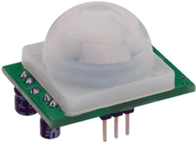
Parallax IR sensor
Hooking up the IR sensor is simple: the positive and negative pins are connected to power, and the third pin (the leftmost pin in Figure 9-8) is connected to one of the Pi’s GPIO pins configured as an INPUT. When the sensor detects motion, it outputs a HIGH signal on the output pin, which then travels to the Pi’s INPUT pin. With the GPIO pin configured as an INPUT, we can read that signal and execute the Python script controlling the toy only when that signal is present.
Before we continue, I need to discuss the important concept of a pullup or pulldown resistor, which I also talked about in the previous chapter. Whenever you have an input in electronics, if that input is not directly reading anything, it is referred to as a floating input . That means the value read from that input could be absolutely anything. We need to define that input’s “empty” state so that we’ll know when that input changes.
To define an input’s “empty” state, we normally connect a resistor (10K or 100K are common values) between the input and either a positive pin (thus creating a pullup resistor) or a ground (thus creating a pulldown resistor). Which one you use is not important—it’s just important that the input is pulled up or down. Thus, if nothing is being read on the pin, and it’s connected to a ground via a pulldown resistor, it will read “0.” When it no longer reads “0,” we’ll know that it’s receiving input.
In the case of our IR sensor, we need to define the value read at the pin when no motion is detected as “LOW,” so we’ll use a pulldown resistor. Luckily, to keep this process simple, the GPIO library allows us to do that in code when we define a pin as an input, like this:
If we connect our IR sensor’s OUT pin to pin 11 on the Pi and initialize that pin with the preceding line of code, everything read on pin 11 will be “LOW” until movement is detected. At that point, the pin will read “HIGH,” and we can call the function that turns on the laser and moves it around.
To test the sensor and our coding prowess, we’ll set up the GPIO pins accordingly. We can use a simple setup to test our code; an LED on a breadboard that will light up when the sensor is tripped. In a Python script, enter and save the following code:
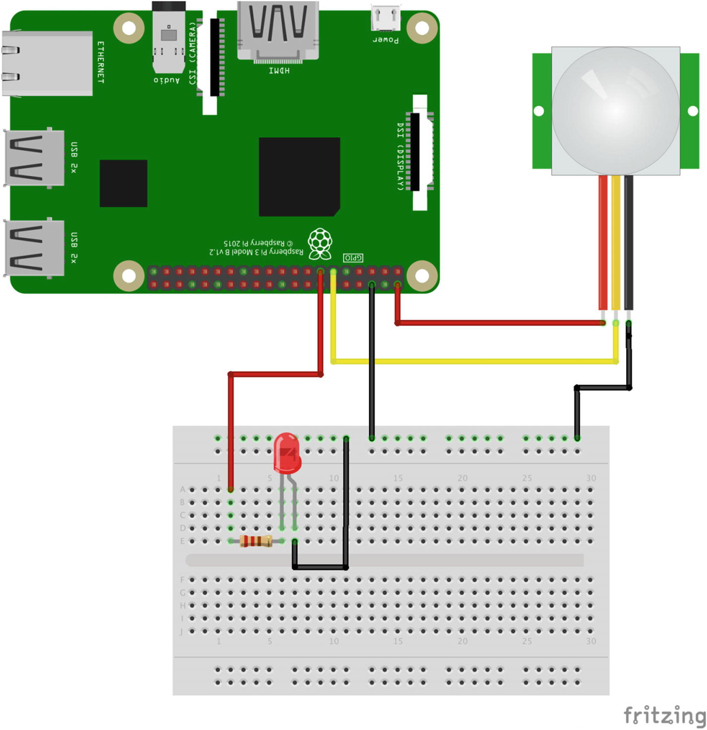
IR sensor and LED test setup
Note
The image in Figure 9-9 was created with Fritzing ( http://www.fritzing.org ), a great open source breadboarding/design tool. It’s cross-platform, very easy to use and learn, and highly recommended.
When you run the script (remembering to execute the code as the superuser, or sudo, since you’re accessing the GPIO pins), the LED should light up when you move your hand around the sensor, and then go out again after a few seconds of non-movement. If it doesn’t work, check your connections and your parts; a burned-out LED can cause all sorts of troubleshooting headaches, believe me!
If everything works as planned, we can now wire the toy and complete all the connections.
Connecting All the Bits
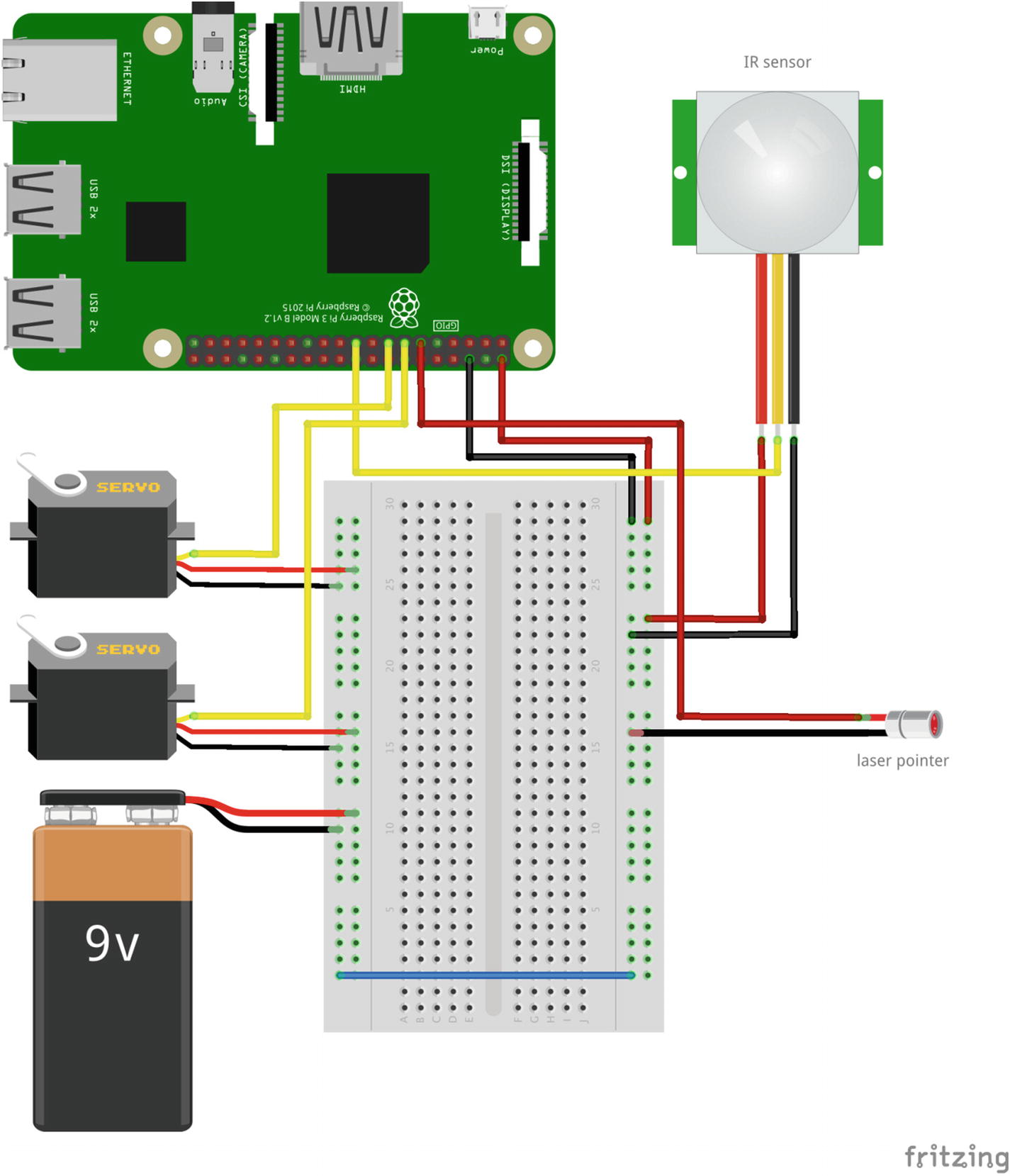
Final component connections
Figure 9-10 is not totally accurate, as the laser pointer is physically attached to the servos, but you can see the electrical connections. The pointer is powered with pin #11, the servos are powered with pins #13 and #15, and pin #19 is the sensor input. Then, everything is given its respective voltage to make it work.
There are a few mechanical engineering tasks involved in the building of this toy, not the least of which is the best way to permanently attach the power and ground wires to the laser pointer. While alligator clips are fine for testing, as soon as the servos start jerking the pointer around in circles, they’re going to come undone.
The best solution to this is to solder the wires to the pointer parts. If you can, use sandpaper to roughen the point of the screw and the pointer casing. If you have room, drill a small hole in the pointer casing to hold the positive wire. Then, attach your wires and solder everything. Your results may vary, depending on your soldering abilities and the materials with which you’re working. You can even use glue, as long as you don’t get glue between the metal contacts of the wires and pointer parts. It’s important that all the wires have a good, solid connection.
The last step is to mount the entire device in some sort of container to hold it all in place and to protect the guts of the machine from feline investigation. You can keep all the parts breadboarded, as long as it’s protected from the end user (your cat). I tend to use PVC pipes in cases like these because a standard servo fits almost perfectly in a two-inch I.D. PVC pipe. In this case, you can mount the lower servo to the edge of the pipe, and most of the wires and guts can be stowed securely inside of it, with a hole drilled in the side for the IR sensor. The Pi won’t fit, but it can be safely stowed away in a separate box, connected to the pipe assembly via long jumper wires. If you decide to go with a Pi Zero (which is completely capable of running this code), it will fit inside the pipe as well, so that may be something to consider.
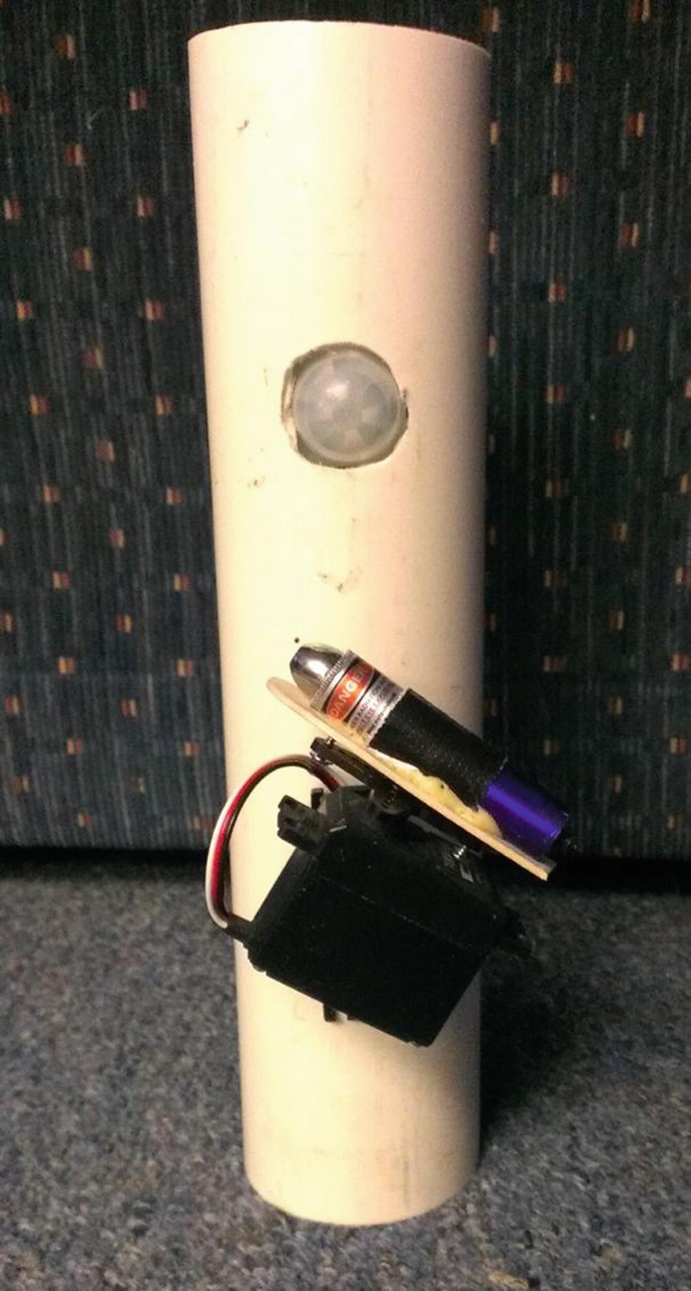
Completed cat toy
It’s not pretty, but your cat won’t care. It can be gussied up, of course, with a cap on the end of the pipe and a coat of paint. Probably the most important detail to remember (and it’s not shown here) is to hide the guts and wires from prying eyes (and paws). The PVC pipe I’ve used here is too narrow, but a pipe with a larger cross-section could easily be fitted with the Pi and all the other guts inside of it, making a self-contained unit. Then, you can add a power switch for the outside, and it’s ready to go.
That should be it! Executing the cat_toy.py script should now keep your feline friend (and quite possibly your human ones) entertained for hours. It’s worth noting that you now have the knowledge and capability to aim and fire a laser with your Raspberry Pi. Yes, it’s a measly little laser pointer, but the concept can easily be applied to any laser, regardless of size or power. Any laser.
Have fun!
Final Code
This code, available on the Apress.com website as cat-toy.py , sets up the GPIO output pins, seeds the random-number generators, and then spins the servos and lights the laser in random motions.
Summary
In this chapter, you successfully constructed a two-axis servo mechanism, hacked a laser pointer to be fired by the Raspberry Pi, and used your programming skills to randomly point and fire the laser to entertain your cat.
In the next chapter, we’re going to get your Pi out of the house and send it into the sky on a radio-controlled airplane.