
Living in modern times can be . . . well, let’s face it: it can be a scary, stressful thing. Bad guys, and the crimes they commit, are everywhere. According to the FBI Crime Statistics website, there were approximately 7.9 million property crimes committed in the United States in 2016, the most recent year for which statistics are available. And although the property-crime rate has been steadily decreasing for the past fourteen years, the days of living on a peaceful street, where neighbors know each other and leave their doors unlocked while they go to work, are long gone.
Luckily, we’re able to protect our homes and also to watch those homes with cameras—both still and video—that are mounted where we need them and are capable of live-streaming that video to any of our always-connected devices, such as our laptops or smartphones. We can outfit our house with sensors, such as motion sensors and trip switches, and use the information gathered from those sensors as a trigger to perform certain actions. If you’re willing to spend the money, you can install systems that do everything from protecting your home from fire and burglars to alerting you to carbon monoxide (CO) leaks.
As it happens, the Raspberry Pi is perfect for doing all those things for quite a bit cheaper than an entire network of closed-circuit cameras and the computer system to run them. Not a lot of computing power is necessary—it’s small enough and power-miserly enough to actually be installed onsite, it can take pictures of important moments via its available camera (infrared, even!), and because it’s connected to a home network it can alert you when something is wrong. Perfect.
Yes, you could get a watchdog. In fact, that’s what many people (some would say normal people) do. But let’s take a moment to consider the pros and cons of owning a dog versus owning a Raspberry Pi. Then, we can start building our home security system with the Raspberry Pi.
Dogs as Security
Dogs (Canis lupus familiaris) are commonly known as man’s best friend, and they have been used as watchdogs for nigh on ten thousand years. They are descended from the wolf and come in all shapes and sizes, from the pint-sized Chihuahua to the giant Great Dane.
One of the jobs of the dog has long been to protect the home from intruders. They are intensely loyal and protective of their human family members and their “den” and will bark at, and even attack, intruders. To keep up this behavior, they require food—sometimes quite a lot of it. And while they are often cute and cuddly and great at keeping your feet warm on cold winter nights, the fact that they have to eat means, unfortunately, that they have to eliminate as well—a stinky undertaking for all concerned.
Dogs are also incapable of being upgraded. The last time I tried to plug a USB cable into my dog, she yelped and ran to my wife. And though dogs can be very cute when they stick their heads out of the window when you’re driving down the road, you can’t upgrade their drivers or use a package manager to download a more efficient gas-elimination program.
The upshot? Dogs are great for watching the house, but they have some serious shortcomings.
The Raspberry Pi as Security
The Raspberry Pi (Rubus strigosus Pi) is commonly known as the hobby-roboticist’s best friend, and it has been used to make all kinds of off-the-wall projects for at least six whole years. These devices are descended from the Acorn RISC Machine from the early 1980s and, as mentioned previously, come in various sundry versions: version 1, version 2, version 3, version 3+, the Zero, the Zero W . . .
The Raspberry Pi does not really have a specific job, but as a computer, it is well known that it will follow all instructions given it to a fault. If you program it to find all prime numbers between 1 and 10,000, it will do so; on the other hand, if you tell it to continue finding prime numbers until a pig flies overhead, it will continue computing until its processor burns out or until Porky grows wings. To do these amazing feats, the Pi does not have to eat, nor does it have to eliminate. The trade-off for the lack of metabolizing organic substances is that the Pi cannot keep your feet warm on cold winter nights. (Actually, I take that back; the version 3 can get kind of toasty when it’s doing some heavy-duty lifting, like video processing. But it’s still small and prickly.)
You can upgrade a Pi, however, with judicious use of the sudo apt-get install command. The Pi welcomes a USB input, and it can be programmed to use sensors to watch your house and its surrounding grounds and to alert you if those defenses are breached. Unfortunately—speaking from experience—people give you very strange looks if you drive down the street with your Pi hanging its head out of the window, but there’s no malodorous gas problem, so there’s that.
The upshot? The Raspberry Pi has some serious shortcomings, but those can be overcome to allow it to watch over your house. And since this is a book on the Pi, that’s what we’re going to use.
Using a Sensor Network
The home security system (and the weather center in Chapter 6) is based on the concept of a sensor network . If a computer is like a brain, sensors are the senses that allow it to gather information from and interact with the physical world. Cameras are like eyes, reed switches are like fingertips, and pressure switches are like toes that have been stepped on by a clumsy dog. Robots would be nothing without their sensors, and any robot brain that needs to interact with the physical world is entirely dependent on that network of sensors.
This, as a matter of fact, is one of the coolest things about the Pi—its ability to easily interface with physical things like sensors . Most modern desktops and laptops have had all of their interesting ports—such as the parallel and the serial port—taken away, left with nothing but a few lonely USB ports and an Ethernet port. This leaves them crippled, unable to easily interact with the “real” world without special equipment and the code to go with it. Meanwhile, the Pi can be plugged directly into a motion sensor via its GPIO pins and let you know, with a few lines of code, whether Slenderman is creeping about in the bushes behind your bedroom.
In our security system, we’re going to use several sensors: an infrared motion sensor, a pressure switch, a magnetic sensor, and a reed, or limit, switch. The motion sensor can be placed anywhere on the grounds. The pressure switch might be useful placed inside a doorway, where an intruder is likely to step. The magnetic sensor can be used to detect if a window is opened, and the reed switch can be used to determine if someone touches a trip wire. We can use the Pi’s onboard camera to take pictures if any sensors are tripped and access those pics any time. Last, we can use our home network to have the Pi send us a text message and/or email message should something interesting happen in our security network—kind of like the security company calling you if they detect an alarm.
This is the sensor network we’ll be working with. It’s kind of basic, but it’s also infinitely expandable. And although we’ll just be using one of each kind of sensor, you can easily add more if you want to (one magnetic sensor for each window in your house, for example).
Understanding a Pulldown Resistor
One important concept to know and remember any time you use an input with almost any circuit is that of the floating input and the pulldown (or pullup) resistor. Basically, whenever a pin (such as a GPIO pin on the Pi) is set to read input from a voltage source, such as a sensor, it is what’s called a floating input until some voltage is read at the pin. Before a voltage signal is sent from the sensor, the level at the pin could be almost anything. This unspecified floating voltage could seriously screw with your program; if you’ve programmed the self-destruct sequence to activate when the pin reads a 2.3V value, and the floating value happens to hit 2.3V, BOOM! We need a way to set the pin to a known value (such as a logical HIGH or a logical LOW) when nothing is being read from it.
The way to solve this problem is to use a pullup or pulldown resistor. This resistor connects the input pin to either Vcc or GND (pullup or pulldown, respectively). That way, if there is no input coming in, the pin will read either Vcc or 0, and we will know that value. This is often done with a physical resistor (10KΩ or 100KΩ, normally), but many development boards (including the Pi) will let you do it “virtually” via software—a huge advantage when you’re working with limited space. Using the GPIO library, you can declare a pin as INPUT and, at the same time, “pull it down” as if with a pulldown resistor with the following syntax:
This defines the value read at pin #11 as LOW until it receives voltage from the sensor; at that point, that voltage is pulled HIGH, and the program can act. When the HIGH value disappears, the pin is again pulled LOW until the process repeats. A pullup resistor does almost the same thing, except the pin is pulled HIGH (to Vcc) until an input appears.
A Shopping List of Parts
A Raspberry Pi (obviously) and power adapter
Raspberry Pi camera module
Pressure switch (such as http://bit.ly/Owc8aN , for example)
Magnetic sensor (such as http://bit.ly/1cis71c , for example)
Motion sensor (such as http://bit.ly/1c35pQp , for example)
Reed switch (such as http://bit.ly/1k6n2RM , for example)
Large spool of Ethernet cable (crimped ends not required—buy in bulk to save money)
Solder, soldering iron, and miscellaneous jumper wires and connectors
Some of these parts are optional, of course; it all depends on how thorough you want your security system to be. You can even add items to your list as your security system grows. Each sensor merely adds to your sensor network, expanding your system’s reach.
Connecting to Your Network Wirelessly
When you set up your Pi as the main controller of your security system, it will have to connect with your home’s network to allow you to remotely log in and administer it and to send you a text message to inform you of an infraction. When you connect to your network, you have the choice of going wired or wireless. Each option has pros and cons, of course, but I highly suggest you use a wireless connection. This is mainly for two reasons: a wireless connection allows you to place the Pi anywhere without having to run Ethernet cable to its location, and a wireless connection is also more secure—a burglar can cut a wired connection to your Pi to render it useless, but not so with a wireless connection.
The main thing you’ll need to do is set up your Pi to have a static IP address. This will allow you to log in to your Pi remotely from anywhere, regardless of whether it has been powered off since your last remote login. If you leave the Pi to receive its IP address dynamically from your home router, it’s possible the IP address will change if the Pi has to reboot, meaning you’ll be unable to log in (because you won’t know what the new address is).
Luckily, setting up a static IP for your Pi’s wireless connection is not difficult, though it can get confusing since the methodology seems to change every time a new Pi model is released. You’ll need to know your router’s address, which is normally something like 192.168.0.1.
In a terminal prompt on your Pi, enter
and scroll to the bottom of the file. This is where you’ll put the information for your particular network and your particular address. Let’s say your router has an address of 192.168.0.1, and you would like your Pi to have an address of 192.168.0.4. Enter the following at the bottom of /etc/dhcpcd.conf:
The first line determines which interface, wired or wireless, you’re setting. The second line gives the Pi’s new static address, and the third line gives the router’s address. Finally, the fourth line sets the DNS server to Google’s DNS.
Once you’ve entered that information, reboot your Pi. Depending on your wireless setup, you may need to use the Pi’s desktop interface to add the password for your personal network. Once this is done, however, your Pi will always have the same address. Now, even if it needs to reboot, you’ll always be able to log into it, using that address to administer it.
Now, to use that static IP, you’ll need to have an SSH server running on your Pi. Depending on how you first set up your Pi, you might have one running already. The easiest way to get your SSH server up and running is to run your raspi-config tool by typing
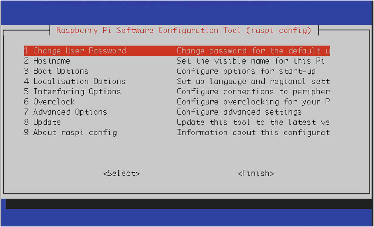
The raspi-config tool
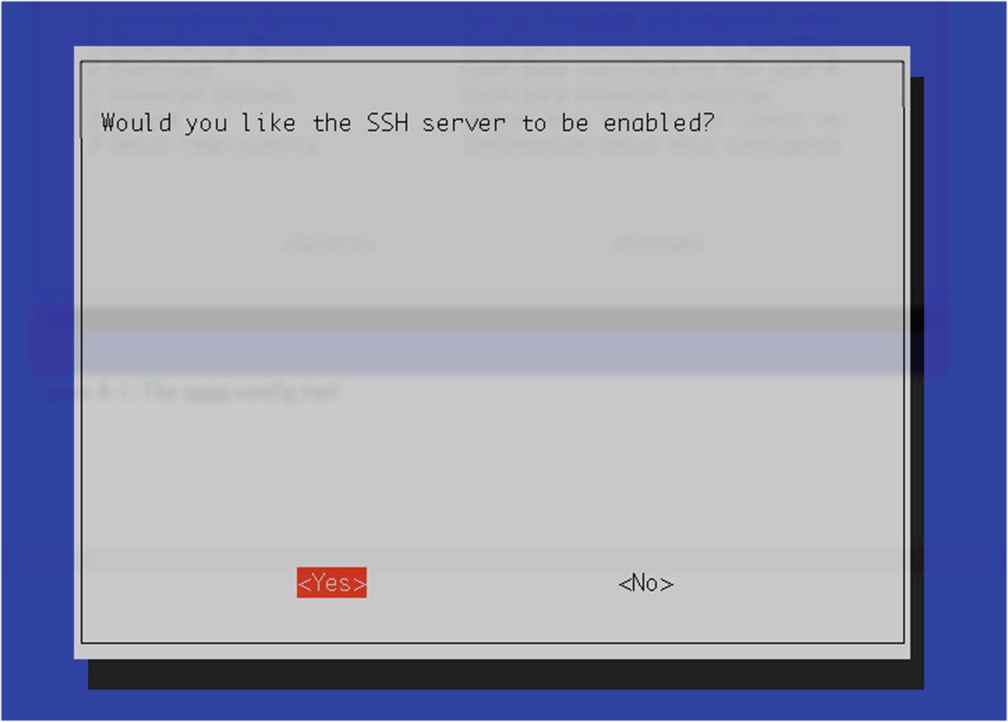
Enabling the SSH server
Then, back out of the raspi-config tool by selecting <Finish> and pressing Enter. Finally, reboot your Pi by typing
in the terminal, and your SSH server should be up and running. You can now remotely log in to your Pi from anywhere. If you’re using a Windows machine, you’ll need to download the free tool PuTTY in order to log into your Pi. If you’re using a Mac or Linux box, ssh is enabled already. Just use the following command:
Enter raspberry at the password prompt, and you’re in! With PuTTY, enter your Pi’s IP address in the box, add the username and password, and click “Connect.” You can now administer your Pi via the command line from anywhere.
Accessing the GPIO Pins
As stated before, and as you’ve already seen if you’ve read some of the other chapters in this book, the Pi’s GPIO pins are the way we interface the Pi with the physical world, such as sensors, servos, motors, and lights. In order to do this, we use a Python library especially designed for this purpose: RPi.GPIO.
To work with the library, you may have to manually install two other libraries. (It depends on which version of Raspbian you’re running.) First, make sure your Pi is up to date by typing
Then, install the Python development packages by typing
Now, in order to access the pins, you call
in the first lines of your program and then configure it by typing

The pinout diagram of the Pi’s GPIO pins
Note
Keep in mind that with GPIO.setmode(GPIO.BOARD), when you refer to pin 11, you’re actually referring to the physical pin #11 (which translates to GPIO 17 in the diagram in Figure 8-3), not GPIO11, which translates to the physical pin #23.
Once you’ve set the mode, you can set each pin to be either an input or an output. Users of the Arduino will probably recognize the concept here:
and so forth. Once you’ve set a pin as an output, you can then send voltage to it (turn it on) by using
or
and subsequently turn it off by using
or
When you configure a pin as an input, remember to set a pullup or pulldown resistor as discussed earlier.
Setting Up the Motion Sensor
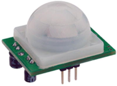
The motion sensor
The sensor we’re using, by Parallax or a close clone, detects motion by detecting changes in the infrared (heat) levels emitted by objects in the surrounding environment. Like most sensors, it then signals that a change has been detected by outputting a “HIGH” or “1” signal on its output pin. It has three pins: Vcc, Gnd, and Output.
The pins are (from the left in Figure 8-4) OUT, +, and –. A nice feature of this particular sensor is that it can use any voltage from 3V to 6V. To use and test it, connect the (–) pin to the Pi’s ground pin (pin #6), connect the (+) pin to the Pi’s 5V pin (pin #2), and connect the OUT pin to one of the GPIO pins.
To test the sensor and our coding prowess, we’ll start by setting up the GPIO pins accordingly. We can use a simple setup to test our code—an LED on a breadboard that will light up when the sensor is tripped. Start a new Python script (let’s call it motion.py) with nano motion.py and enter the following:
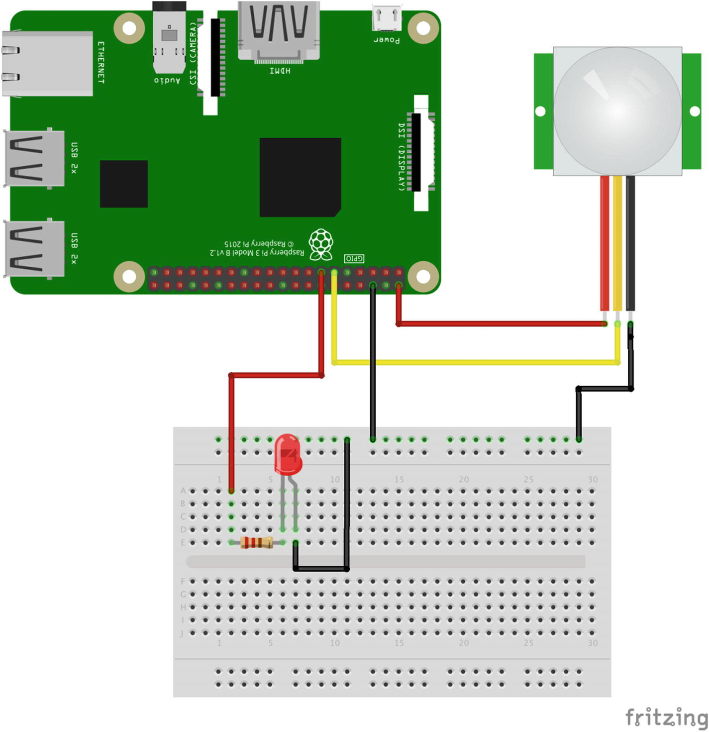
Testing the motion sensor
When you run the preceding script (remembering to use sudo because you’re accessing the GPIO pins), the LED should light up when you move your hand around the sensor, and then it should go out again after a few seconds of nonmovement. If it doesn’t work, check your connections and your parts—a burned-out LED can cause all sorts of troubleshooting headaches, believe me!
Leave the sensor attached as it is, as we’ll be using it in our system, and let’s move on to the reed switch.
Setting Up the Reed Switch

The limit switch
The long arm protruding from the body of the switch allows objects that are far away to close the switch’s contact—the small hump protruding from the switch. It has three terminals, but we’re only going to use two because we’re only interested in when the switch closes.
In our case, we’re going to use a limit switch to determine if a trip wire has been pulled. You can mount the switch on a wall and run a thin thread or fishing line from the opposite wall to the switch’s lever. Position it so that if someone were to walk into the thread, they’d pull the lever down, activating the switch.
Because we’re using a physical switch, rather than a sensor like the motion detector, it’s important that I introduce you to the concept of debouncing . A common aspect of physical switches is that, because they’re often made of spring metals, when they are first activated they tend to bounce apart one or more times, often in almost microscopic increments, before making a steady contact. The result is a very fast on-off-on-off-on-off “chatter” before the voltage settles at a steady HIGH or LOW. To combat this, we debounce the switch by reading from it only when it’s no longer bouncing back and forth, like so:
This little script illustrates the concept quite nicely. It ignores a button press if it occurs less than 0.05 seconds after the last one.
So, to test our switch, let’s hook it up to some GPIO pins and make sure we can read the input when its state changes. Just using the switch, connect your Pi’s power pin (#2) to the switch’s leftmost pin, as shown in Figure 8-7. Then, connect the middle pin to your Pi’s pin #11. Try the following code:
When you run this script (remembering to use sudo), pressing the switch will send voltage directly through it from pin #2 to pin #11, thus registering as HIGH at pin #11. It’s a debounced signal, and the Pi should print “Button pressed” when you press the button. Congratulations! You’re able to read when a switch is pressed!
Let’s move to the next switch.
Setting Up the Pressure Switch

The pressure switch
Rather than a physical lever and a button, a square pad is used that simply registers pressure as a change in voltage. For this reason, it’s even easier to connect than the limit switch. Connect your Pi’s pin #2 to one of the leads, and connect the other lead to pin #11. Then, run the same script as you did for the limit switch and test it by pressing down on the pad with your finger. Voilá! You’re now reading a value from a pressure switch! This is perfect for reading a footstep from underneath a welcome mat, for instance.
Connecting the Magnetic Sensor
The magnetic sensor (shown in Figure 8-8) is a little device that, while not commonly used outside of certain specific applications, can come in handy for applications like ours. It measures the surrounding magnetic field and sends a signal when that field changes. For that reason, it is very good at determining when the relative positions of two pieces of metal have changed.

The magnetic sensor
To test our magnetic sensor , we can again use the switch.py code we’ve been using. Connect the jumper wires that came with the sensor to the connector block on the sensor, then connect them to your Pi: red to pin #2, black to pin #6, and white to pin #11. Now, just change the code to read
and run the script. Your terminal will remain blank until you wave the magnet past the sensor. (You might have to experiment with different distances and speeds. My experience is that the magnets have to pass pretty closely to register.) At that point, it will tell you “field changed.” After a little experimentation, you’ll know just where you’ll have to mount the magnet in order for the change in field readings to influence your security system. Now you can mount the sensor on one pane of a sliding window, for instance, and a magnet on the other pane, and should the window slide open, the magnetic sensor will register the movement of the magnet.
Setting Up the Pi’s Camera
Finally, one of the features that makes the Pi attractive as a security-system lynchpin is its ability to take pictures from a small built-in camera. While this means that the Pi must be positioned in a strategic location to pick up anything interesting, the Pi is so small that finding a good place for it shouldn’t be a problem.
To take pictures, you’ll have to have two components working on your Pi: the wireless and the camera. I discussed the wireless setup earlier; the camera can also be enabled with the raspi-config tool, if you haven’t configured it already.
Once you’ve enabled the camera, you have two commands you can use: raspistill (to capture pictures) and raspivid (to capture video). Each can be used with various flags and options to change the frame size, capture rate, and other configurations.
We’re interested in taking still pictures, however; streaming video via live feed, while possible, requires a few extra software tools that can be difficult to set up. Taking a picture is a simple call to raspistill from the command line, or the use of the picamera Python library (which is what we’ll use). To try it out, enter the following in a new Python script:
and make sure that it’s been enabled with your raspi-config tool. A still image labeled “image.jpg” will be stored in the current directory. We can put this picture-taking functionality in a take_pic() function and call it whenever a sensor is tripped. We then have evidence, should we need it for corroboration!
Sending a Text Message from the Pi
In my opinion, having your Pi send you a text message when something unusual happens is one of the coolest parts of the project, and it’s particularly useful if you’re going out of town. A notification from your Pi can let you know that you need to call your neighbor (or the police) and have them check on your house. It’s really pretty simple: the Pi uses the local network to send an email message, which is then translated by your mobile carrier into an SMS, or text message.
You’ll need an email account that’s web-accessible; most of us have a Gmail or Yahoo account, for instance. You’ll also need to know how to send a text via email with your mobile carrier. Each carrier is slightly different, but the basic concept is the same—sending an email to a certain number (<mobile_number>@txt.<carrier>.net, for example) has that email delivered as a text. I use AT&T, and if you send an email to 19075551212@txt.att.net, it will be delivered as a text. Check with your particular carrier as to what address and format to use; if the information isn’t easily found on their website, ask a tech. Then, using Python’s smtplib library, you can send an email to your phone.
It’s probably easiest if I just show you with the following code:
Calling the send_text() function with a string such as “OMG I’m being robbed!” will send you a text message. Obviously, this code is designed to work with AT&T and uses a Gmail account. You’ll need to modify it as necessary for your carrier and email provider. Gmail’s smtp access is through port 587, as you can see in line 9 in the preceding code; this may differ for Yahoo or MSN. You can call this function when you detect an input at any of your sensors, and you can even adjust the string sent according to which sensor is tripped.
Implementing the Callback
There’s one significant idea left to explore in this project, and that is the concept of the callback . You may have noticed that there’s no easy way to check each switch; you have to continue to “poll” each switch and hope that nothing unusual happens while you’re doing something else. Not a big deal if you have only three or four switches and sensors, but should you start adding to your network, the delay between something happening and your being notified about it can get unwieldy quickly; limit switch #2 could get tripped while you’re checking magnetic sensor #16, and you won’t know about it for another two seconds. By that time, of course, the intruder could have snuck by the trip wire and be well on his way to breaking all of your dishes or stealing your Star Wars memorabilia.
Luckily, Python (and the Raspberry Pi) have an answer to that switch-checking problem. It’s embedded in the RPi.GPIO library: the threaded callback interrupt. What this allows us to do is to start a different program thread for each switch. Each thread will go into a “waiting” mode, doing nothing, while the rest of the program (and the rest of the threads) go on about their business. If and when the switch gets tripped, it immediately issues a callback, or interrupt, to the main program to let it know (“Hey! I’ve been tripped over here!”), and then it performs whatever function we want it to. In this way, we can be sure we won’t miss an important button press or switch trip. Meanwhile, all of the other threads continue their holding pattern. At the bottom of this pattern, one switch functions as a base; if that one switch is tripped, you can end the program. Otherwise, it continues inside a while loop.
This callback feature is accomplished using either one of two functions: GPIO.wait_for_edge() or GPIO.add_event_detect(). GPIO.wait_for_edge() does just that—waits for a rising or falling edge on any particular pin and then acts when it detects that edge. GPIO.add_event_detect(), on the other hand, waits for a rising or falling edge on a particular pin and then calls the function declared in its parameters. You can see them both in use in the final code later in this chapter. Just be aware that for each sensor or switch, we have a unique callback function—one that is unique to that sensor—so that we know exactly which switch has been tripped.
Connecting All of the Bits
Now that we’ve determined how to use all of the pieces of this puzzle, let’s quickly go over how to connect everything.
You’ll need to use the Ethernet cable to make all of your connections; it’s strong, easy to work with, and (mostly) waterproof. Strip the outer casing to reach the wires inside and chop all but the two or three wires you need to connect each sensor to your Pi. You’ll need a small breadboard to place next to the Pi because everything should share a ground.
Find a good place to mount your Pi, where you can plug it in (no worrying about batteries) and mount the camera so that it can take good pictures of the action. Once you’ve found a place, you can use poster putty to hold everything in place. You may want to use a plastic or metal project box to keep everything together.
Finally, find good places for all of your sensors. Remember, they don’t need to be in sight of the Pi: as long as you can run Ethernet cable to them, it’s a good spot. Attach the cables securely and in such a way that nobody trips over them. Connect all of the negative wires to your common ground row on your breadboard, and then connect each positive wire to a GPIO pin. At this stage, it’d probably be a good idea to write down what sensor is attached to which pin so that you can reference it in your code.
The Final Code
That completes all the individual parts of this project. All that’s left is to put them all together in your final code, like so (you can download the final code file, called home_security.py, at apress.com):
Summary
In this chapter, you learned about what sensors are, the concept of a sensor network, and how to hook different sensors to your Pi’s GPIO pins. You set up the limit switch, pressure switch, magnetic sensor, and motion sensor (which we will also use in the Pi-powered cat toy in the next chapter). With the knowledge you’ve gained here, you now have the ability to create a full-sized security system, with its breadth limited only by the amount of sensors you have and how much wire you’ve got to tie them all together.