
Submersibles, both those remotely operated and autonomous ones, have been used for both scientific research purposes and private enterprise for several decades. They have studied life on the barren intercontinental plains, explored volcanic vents in the middle of the Atlantic Ocean, and gone places impossible for humans to go. In the commercial world, they were thrust into the spotlight during the Deepwater Horizon oil disaster in 2010. A fleet of submersibles was used to cap the oil well and stop the spill in 5,000-foot depths, far below what human divers could reach. They are routinely used to conduct maintenance on deep-sea oil rigs and offshore wave farms.
There are basically two kinds of submersible: ROVs and AUVs. ROV stands for Remote Operated Vehicle and describes a sub that is remotely controlled from a ship via a tether—a cable that provides both power to the sub and two-way communication with its onboard systems. Ordinarily, an onboard camera sends a video signal up the tether to a monitor in the control room, where a specially trained operator uses the video feed to control the sub with a high-tech version of an Xbox controller. The remote operator controls the sub’s propulsion, steering, and depth, and that person is also able to work the vehicle’s grippers and sample collectors, assuming it is so equipped.
AUV , on the other hand, stands for Autonomous Underwater Vehicle and describes a submersible that works without human intervention or control. It may or may not use an onboard camera; if it does, the video from the camera is often used only for data-gathering purposes, not for navigation. An AUV has an array of onboard sensors and a relatively sophisticated onboard computer that is programmed to perform a variety of tasks and movements based on information from the sensors.
Using the Raspberry Pi, you can actually construct both an ROV and a full-scale AUV, but for our purposes we’re going to make a (much simpler) remotely operated vehicle. We can use the Pi’s onboard camera to take snapshots of our underwater explorations, and we can control the sub with a hacked Wii nunchuk. You won’t be able to navigate via video, because sending a video signal through a cable to an external monitor is slightly beyond the scope of this book, but as long as you don’t go too deep, you should be able to follow the sub with a raft or small boat and direct it from the surface. Again, to keep the project within the scope of a single book chapter, we’re going to avoid depth control as well; instead, we’re going to make the sub neutrally buoyant.
Precautions in The Event You Fry Your Pi
Buy an extra Pi to use in your submersible. It’s relatively inexpensive (especially if you use the Pi Zero or Zero W), and should you happen to fry it, you’ll still have your original Pi with all of its tweaks and added modules. If you duplicate your SD card (see the next bullet point), the submersible Pi will be exactly like your regular one.
Back up your SD card regularly, just as you do with your computer’s hard drive. If you back up as you go, you won’t lose too much hard work if something happens to the card.
A Shopping List of Parts
Raspberry Pi
Raspberry Pi camera kit—available from Adafruit, Amazon, and Sparkfun
Motor Driver—dual L298 H-bridge ( http://www.sparkfun.com/products/9670 )
Nintendo Wii nunchuk controller
1 Wiichuck adapter ( https://www.dfrobot.com/product-91.html )
Headers
2 DC motors
Model propellers
2 battery packs (the Lithium-Polymer packs used by RC hobbyists are a good choice)
1 waterproof enclosure—think Tupperware or something similar
1 tube of 5200 marine waterproofing sealant
PVC pipe and elbow joints
Assorted zip ties
Chicken wire or plastic mesh/netting
Wire—red and black, 18 gauge
Ethernet cable—25–50 feet (buy it in bulk, if possible, as you won’t need the plastic terminals, just the cable)
Wax
Caulk
Accessing the Raspberry Pi’s GPIO Pins
One of the features that makes the Raspberry Pi so incredibly useful is its GPIO (General Purpose Input/Output) pins. Using a specific Python module that comes preinstalled on the Pi, the GPIO pins can be directly controlled, sending voltages to external devices and reading inputs that can then be used in programs.
GPIO: WHAT’S THE BIG DEAL?
GPIO pins are like some of the ports on an old computer. An easy way to interface with the external world used to be either the serial port or the printer (parallel) port. Both could be accessed with the correct programming libraries, sending signals directly to each pin. But as technology progressed, both ports disappeared and were replaced with USB and Ethernet connectivity. As a result, it became much more difficult to control external devices from a programming standpoint, and this is why many people are excited by the possibilities offered by the Pi’s GPIO pins.
To configure your Pi to access the GPIO pins programmatically, you may need to install the correct development kit and tools. Just enter
When that finishes, type
Note
python-rpi.gpio may already be installed, depending on your Raspian version. Depending on the date you’re reading this chapter, it may also return an error of “Unable to locate package.” No big deal—it’s most likely already installed.
You’re now ready to access the pins. The Python module used to access them is the RPi.GPIO module. It is normally called in the first lines of your program by typing
and then configured by typing
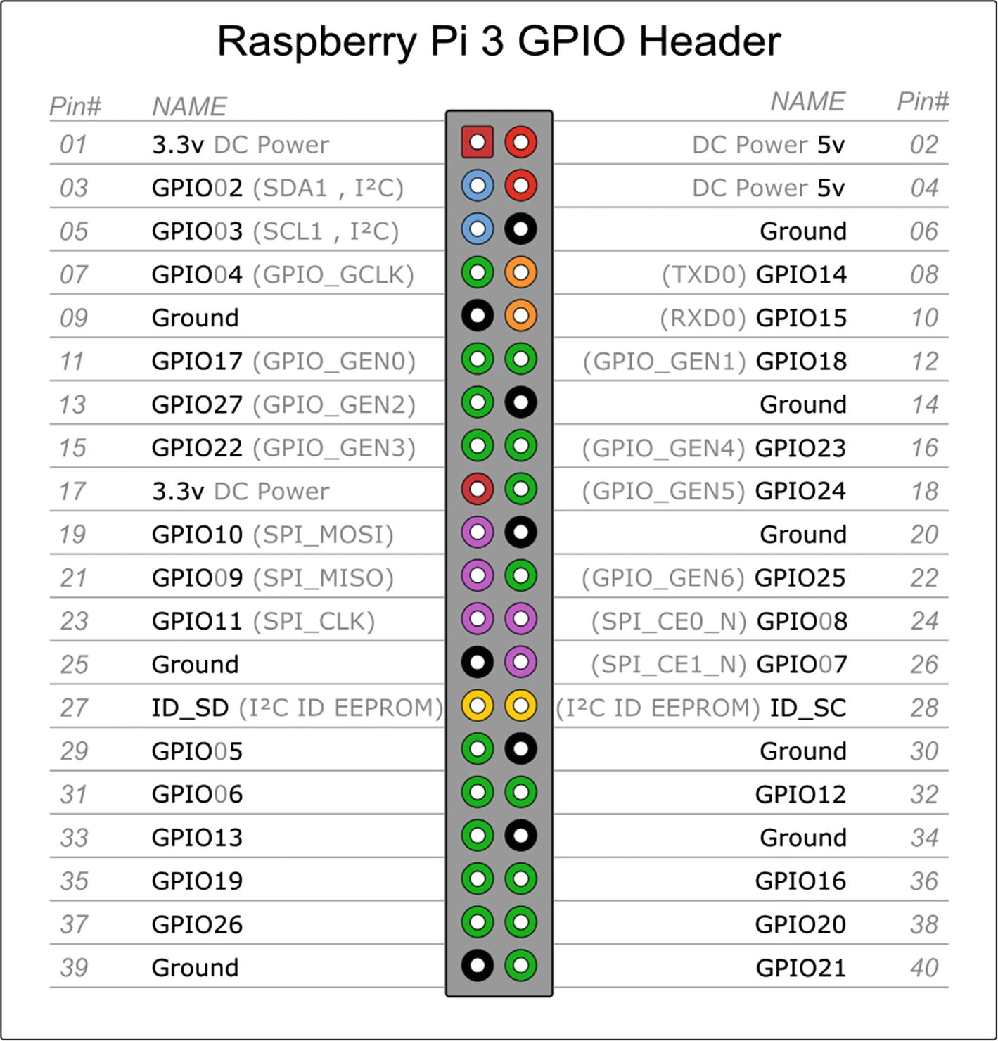
Raspberry Pi 3 pinout
Note
Keep in mind that with GPIO.setmode(GPIO.BOARD), when you refer to pin 11, you’re actually referring to the physical pin #11 (which translates to GPIO17 in the diagram in Figure 12-1), not GPIO11, which translates to physical pin #23.
Once you’ve set the mode, you can then set each pin to be either an input or an output. Users of the Arduino will probably recognize the concept here. Type the following
and so forth. Once you’ve set a pin as an output, you can then send voltage to it (turn it on) by typing
or
and subsequently turn it off by typing
or
If the pin has been configured as an input, you can query it to see if a button or switch connected to it has been pressed. However, an important caveat here is that if the pin is merely declared an INPUT, it is defined as “floating” and has no defined voltage level. In this case, we need to connect the pin to a ground so that it is always LOW (0) until we press a button. This is done by putting a resistor between the pin and a common ground. Luckily, the RPi.GPIO module allows us to do this in software by typing the following:
At this point, you can “poll” the pin at any time by typing
Insert this simple piece of code in a loop in your script; every time the loop runs, the script will check the pin’s status. We’ll use this functionality in our final submersible program to trigger the camera to take pictures.
Installing the Pi Camera Board
The submersible we’ll build will be equipped to take pictures, either at preset intervals or at the press of a button. Obviously, this means we need to install the camera module that interfaces with the Pi.
When you get the camera board, it will most likely come in a plain white box, inside of which is an anti-static gray bag containing the camera board. Make sure you have discharged any static electricity from your body (because the camera is very sensitive to static) by touching a good ground; then, remove the camera from the bag.
Connecting the Pi’s camera cable
You should have enabled the camera support when you set up your Pi in Chapter 3; if you didn’t, however, it’s not difficult. From the terminal, type
and
to make sure your Pi is running all the latest kernel fixes and software updates. When both of those finish, type
to start the configuration program. Navigate to the “camera” selection and click “Enable.” Then, select “Finish” and reboot the Pi.
When the Pi comes back up, you can use its built-in camera functions, raspistill and raspivid, to experiment with the camera. For a full list of commands, simply enter
or
at the command prompt for instructions. For example, to take a still picture in a “cartoon” format, simply type
and the image will be saved in whichever directory you happen to be in. You can change the image resolution, height, width, effects, and delay and even set up a time-lapse situation using the -tl flag (which we may use later).
Controlling the Sub
The Wii nunchuk
The nunchuk communicates via a protocol known as I2C, or I2C, or IIC , which stands for Inter-Integrated Circuit. If you’re working your way through the projects in order, you may remember the I2C protocol from Chapter 6, “The Weather Station.” I2C was created by Philips in the early 1980s as a way for different devices to communicate on a single bus (communication wire). It has since undergone several revisions, but the basic concept remains the same. On an I2C bus , one machine serves as a “master” and can be connected to a variety of different “slaves.” Each machine can communicate on the same set of wires, using a clock signal transmitted by the master to synchronize the communication. Luckily, for our purposes, the Raspberry Pi can utilize the I2C protocol over some of its GPIO pins, and the communication is relatively simple because there are only two devices communicating: the Pi, serving as the master, and the Wii nunchuk, the solitary slave.
Attaching the Wiichuck Adapter
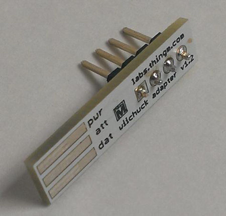
Headers soldered to the Wiichuk adapter
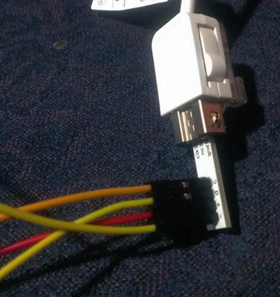
Correct positioning of Wiichuk adapter
Caution
You should connect the nunchuk to the Pi’s #1 pin (3.3V), not the #2 pin (which is 5V). The Wii’s nunchuk is designed to run on 3.3V, not 5V. Although it will work with 5V, it can severely shorten the life of the controller.
Activating the Pi’s I2C
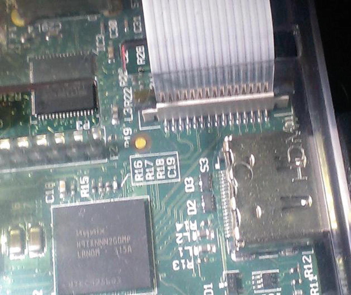
The Raspberry Pi has two pins, #3 and #5, that are preconfigured to be the I2C protocol’s SDA (data) and SCL (clock) lines, respectively, so it can easily communicate with I2C devices. The Pi also has an I2C utility that makes it possible to see the devices that are currently connected. To install it, type
If you’re using a recent version of Raspbian, such as Wheezy or Stretch, these should be installed already, in which case you’ll just get a note telling you that they’re already the newest version.
Now you can run the I2C utility tool called i2cdetect to make sure everything is working and see what devices are connected. Type the following line:
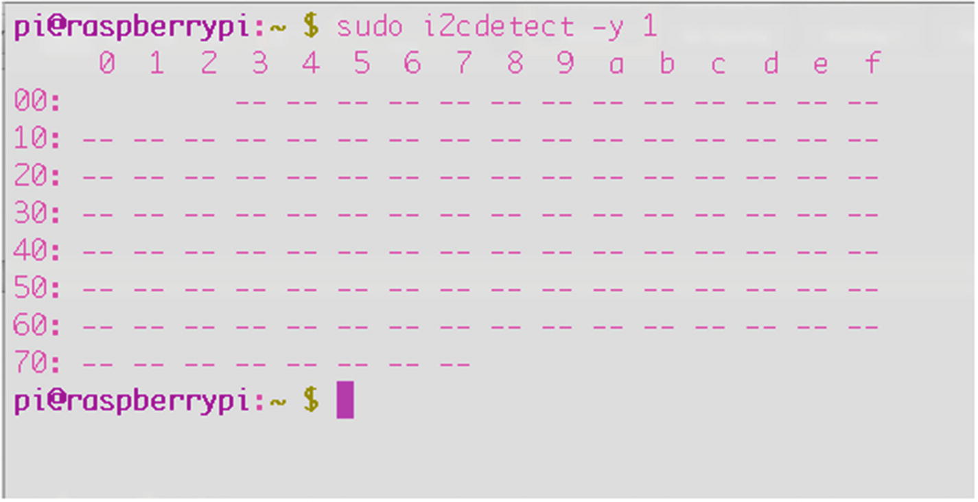
The i2cdetect tool
In the figure, no devices are present, which makes sense because we haven’t plugged any in yet. But you know that your tools are working correctly. If you’ve plugged in your Wiichuk adapter, you should see an entry at #52, which is that tool’s I2C address.
Tip
If you have trouble getting results, and you’re positive you hooked up all the wires and devices correctly, check that all your wires are intact. I have lost hours and hours troubleshooting a build, only to find that one or more of the cheap jumper wires I was using was broken inside the insulation, meaning I wasn’t getting signals where I was supposed to. It happens more often than you think!
Reading from the Nunchuk
You’re now ready to read from the nunchuk. Eventually, of course, we’re going to translate signals from the nunchuk into commands for the motors, but it might be instructional to see what signals we’re getting to begin with. To do this, let’s create a Python script that imports the correct modules, listens for signals from the nunchuk, and outputs them to the screen. There are seven signals that get sent over the wire: the x and y positions of the joystick, the state of the “Z” and “C” buttons on the front, and the x, y, and z states of the nunchuk’s built-in accelerometer. We won’t use all of these for the sub, but we can still take a look at them.
Here’s the full script for you to type in:
If you haven’t already, create a folder for your submersible program, save this script in that folder as nunchuktest. py , and run it. After importing the necessary modules, the script creates a “bus” over which all communications will be made with the nunchuk. It then begins communication by writing to the nunchuk’s I2C address (bus.write_byte_data()). It then enters a loop where it continuously reads the 5-byte strings coming from the nunchuk (data0, data1, and so on) and categorizes them as joystick directions, accelerometer readings, and button presses, in that order. Then, it prints those values to the screen and repeats the process.
Because it involves reading and writing to the I2C bus, you’ll have to run it as root, so type the following:
As soon as the script starts, it will show you a running status report of all the nunchuk’s sensors, updated in real time and formatted like so:
With the script running, try moving the joystick, pressing the buttons, and shaking the nunchuk to watch the values change. You now know how to read values from the nunchuk, which we’re going to use to drive the motors.
The Nunchuk and LED Test Side Project
As a little side project (and as a test for my nunchuk-reading ability), I hooked up six LEDs to a small breadboard and some GPIO pins so that they would light up depending on which way I moved the joystick or pressed the buttons. This might be a worthwhile test to conduct to make sure that not only are you reading the values, but also that you are able to do something with those values. In this case, choose four GPIO pins and set them as outputs. Connect those pins to a resistor and the positive leg of your LEDs connected in parallel (as shown in Figure 12-7), tie all the grounds together, and run the following script:
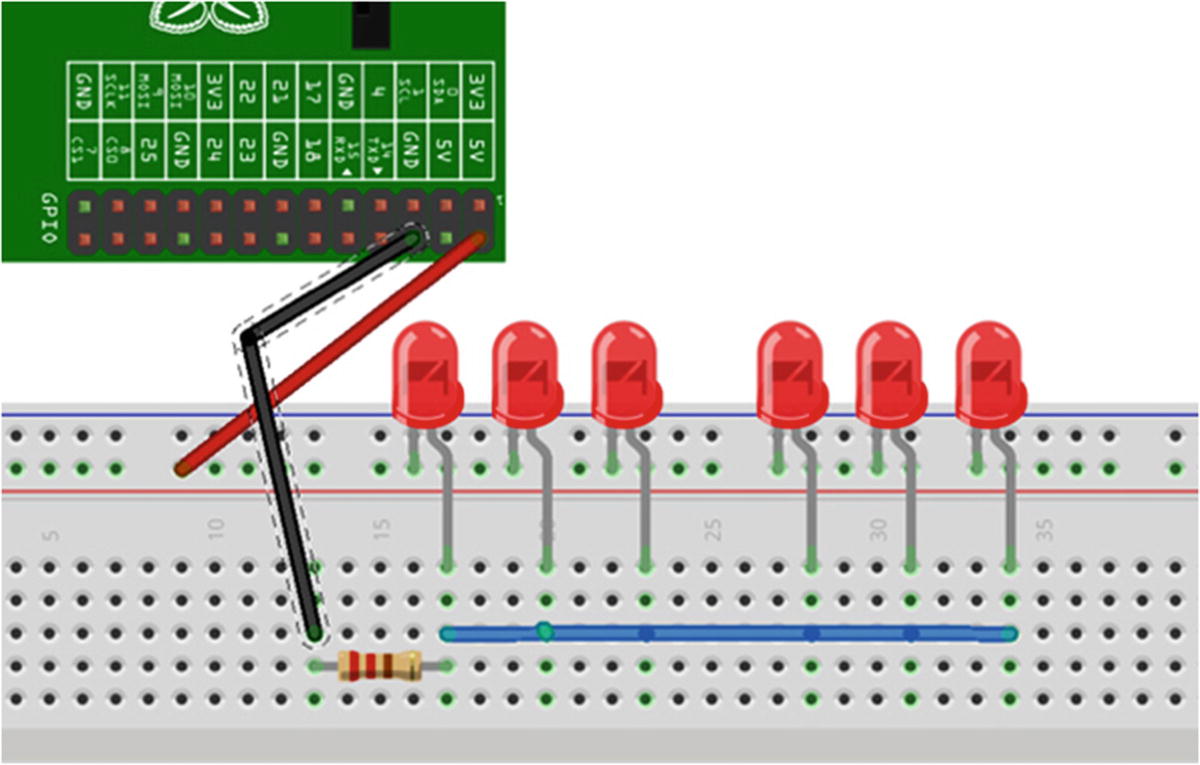
LED test setup
As mentioned earlier, the code first creates a “bus” over which all communications will be made with the nunchuk. It then begins communication by writing to the nunchuk’s I2C address (bus.write_byte_data()). It then enters a loop where it continuously reads the 5-byte strings coming from the nunchuk (data0, data1, and so on) and categorizes them as joystick directions, accelerometer readings, and button presses, in that order. The values of those strings indicate what each component of the nunchuk is doing: if buttonZ is True, for example, the button has been pressed. Likewise, the joystick’s y-direction value indicates whether the joystick is being pushed forward or pulled back. The long sequence of if-elif statements simply iterates through the received values and lights the corresponding LED.
Running it (again, using sudo) should result in different LEDs lighting depending on what you’re doing with the nunchuk.
As you can see, hooking the LEDs in parallel means that they all share a common ground and a common high-voltage line. In contrast, if you were to connect them in series, the positive leg of each LED would hook to the negative leg of the next LED, with a resistor between the last LED and either the positive pin or negative pin of the Pi.
Controlling the Sub Motors and Camera with the Nunchuk
Now that we’ve got the nunchuk working, we will use it to control the motors of the sub, which involves using the L298 motor controller chip . Ordinarily, we can’t drive very powerful motors or servos with the Pi, because the Pi can’t source (supply) enough current to drive them. To get around this limitation, we use a motor controller chip such as the L298. Chips like this, called H-bridges , allow you to hook an external power source to your motors and use the Pi to turn the motors on and off as needed. The L298 chip costs only a few dollars and can be used to drive incredible amounts of current and voltage—up to 4 amps and 46 volts. It’s commonly used with hobby robots and is perfect for this type of application.
However, though the chip is cheap, connecting it to your Pi and the motors can be complicated because you need to use several 10nF capacitors and some flyback diodes to protect the Pi from voltage spikes coming from the motors. For that reason, I highly recommend getting the L298 motor driver board from Sparkfun, as mentioned in the “A Shopping List of Parts” section. It makes the connections much simpler: you plug in the external source, input signals from the Pi, and output wires to the motors, and you’re done. For the rest of the chapter, I’m going to assume you’re using the Sparkfun board . If you decide to breadboard the chip yourself, some good schematics can be found online.
Joystick forward = both motors spinning
Joystick left = right motor spinning
Joystick right = left motor spinning
C button pressed = take still picture with camera
Z button pressed = take video with camera
Motor Values and Settings
ENA Value | ENA = 1 | ENA = 1 | ENA = 1 | ENA = 0 |
IN1 Value | IN1 = 1 | IN1 = 0 | IN1 = 0 | - |
IN2 Value | IN2 = 0 | IN2 = 1 | IN2 = 0 | - |
Result | Motor A spins clockwise | Motor A spins counter-clockwise | Motor A brakes | Motor A stops |
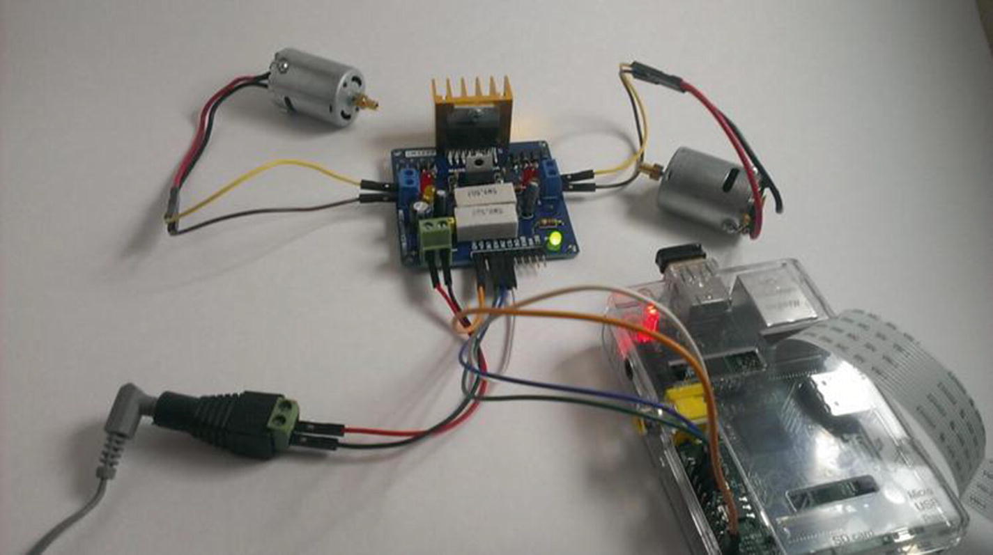
Motors and the motor controller connected to the Pi
Obviously, all we need to do is set up three GPIO pins for each motor. At the same time, we read the GPIO pins set as I2C inputs and set the motor pins HIGH or LOW, depending on the signals we’re getting from the nunchuk. We’ll also check for button presses in order to activate the camera . (Figure 12-7 shows the connections for one motor, not both.)
We can set each command for the camera (take_picture, take_video, etc.) within its own function and call that function when the appropriate button is pressed on the nunchuk. Similarly, we can set up functions to run the motors and call those functions according to the position of the joystick. All of this happens within a while loop and continues until we kill the program or the batteries die.
Starting the Program Remotely
There are several ways to get the Python program running once you power up your submersible, as you won’t have a keyboard, mouse, or monitor connected to the Pi. It would seem that the easiest way would be to set up a static IP address, remotely log in to the Pi from a laptop, and then start the program from there. However, this will only work if you are logged on to a wireless network, and chances are that there won’t be any networks available out on the middle of a lake (or ocean, or wherever you happen to be using your submersible).
You could set up an ad-hoc network , which is where the Pi and your laptop create a small, exclusive network, and then log in to the Pi from your laptop. However, setting up an ad-hoc network can be problematic, and if it doesn’t work for some reason, you’ll be unable to access your Pi, rendering your submersible useless.
After some thought, I decided that the best way to proceed would be to simply start the sub control program automatically when you start up your Pi. That way, you can turn it on, send power to the motors, and proceed to work with your sub.
To do this, all we need to do is to edit one file—your cron scheduler. The cron scheduler is a job scheduler you can edit. It enables you to schedule tasks and scripts at specified times and intervals. To edit it, you open the file called the crontab by typing
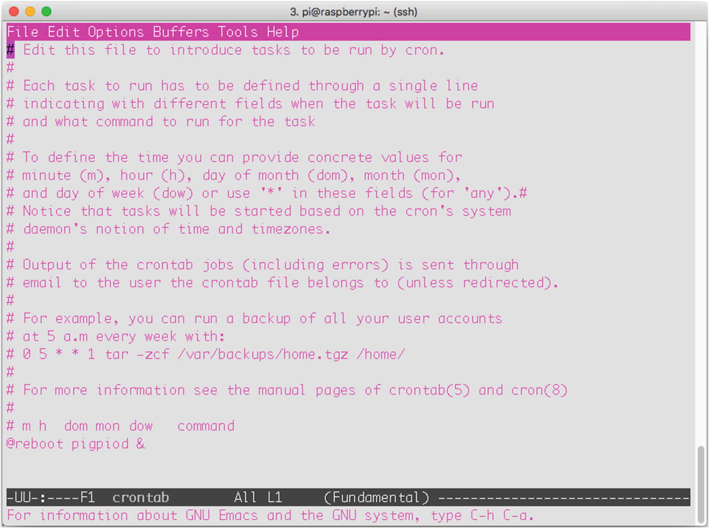
The user’s crontab file
Scroll down to the end of the file and enter the following line:
This is the specific path to your Python script (assuming you’ve saved sub.py in the submersible folder on your desktop), and the & tells cron to run the job in the background, so as not to interfere with the normal startup routine. Save the file. The next time you reboot the Pi, sub.py will be running—test it if you like!
The Final Code
Save the following code on your Pi, preferably in its own folder. It’s also available as sub.py on the Apress website.
Constructing the Sub
At this point, we’re ready to start building the actual submersible. Gather your parts together: the PVC pipes and elbows, waterproof container, glues, screws, and the rest. Remember that the design I illustrate in the following sections is just that—an illustration, not a step-by-step instruction sheet. As long as you end up with a frame of some sort upon which you can mount your waterproofed Pi enclosure and waterproofed motors and propellers, you will have succeeded in this task.
Note
Construction plans, particularly motor-waterproofing procedures, have been influenced heavily by the Seaperch program ( http://www.seaperch.org ), a program designed to teach students of all ages about building a remote-controlled submersible and to encourage involvement in engineering and mathematical fields. It is a valuable program, and I highly endorse its goals.
Building the Frame
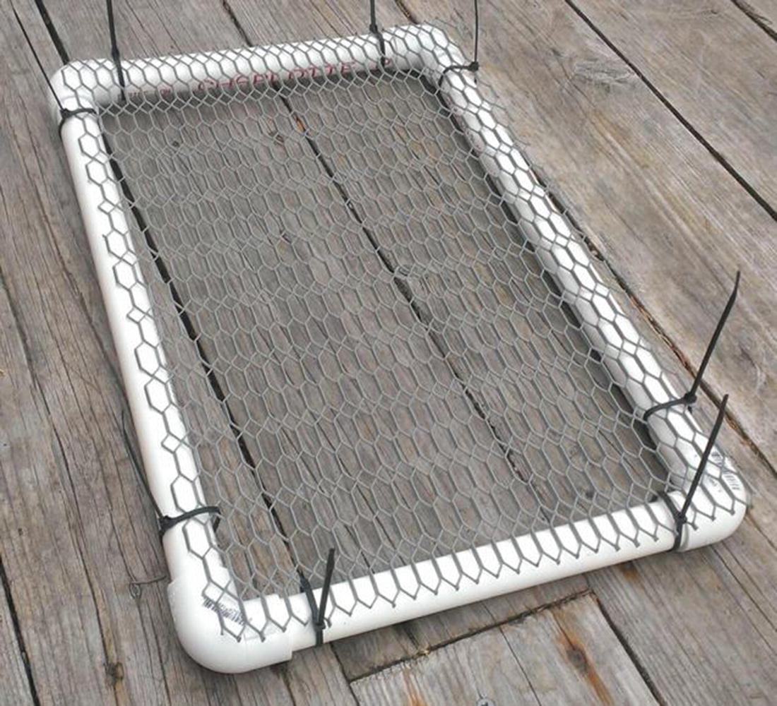
The sub platform
This is your sub’s body. I’ve left it large enough to add strips of Styrofoam on the sides if I need to change the buoyancy, though I shouldn’t have to, seeing as how the Pi’s enclosure is filled with air.
Creating the Pi’s Enclosure
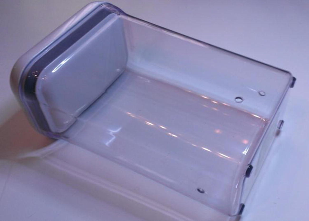
Waterproof Pi enclosure
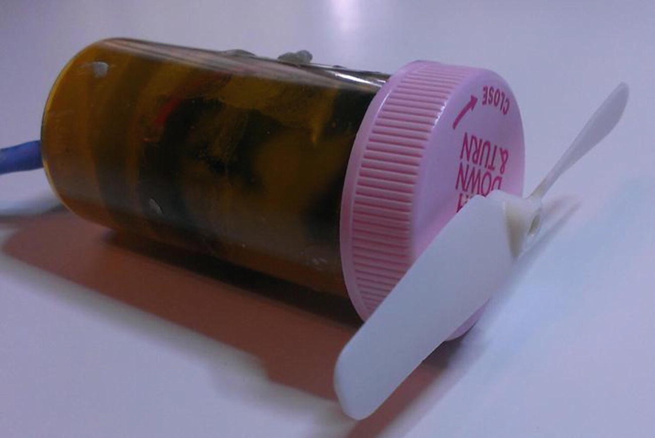
Waterproofing the Motor Enclosures
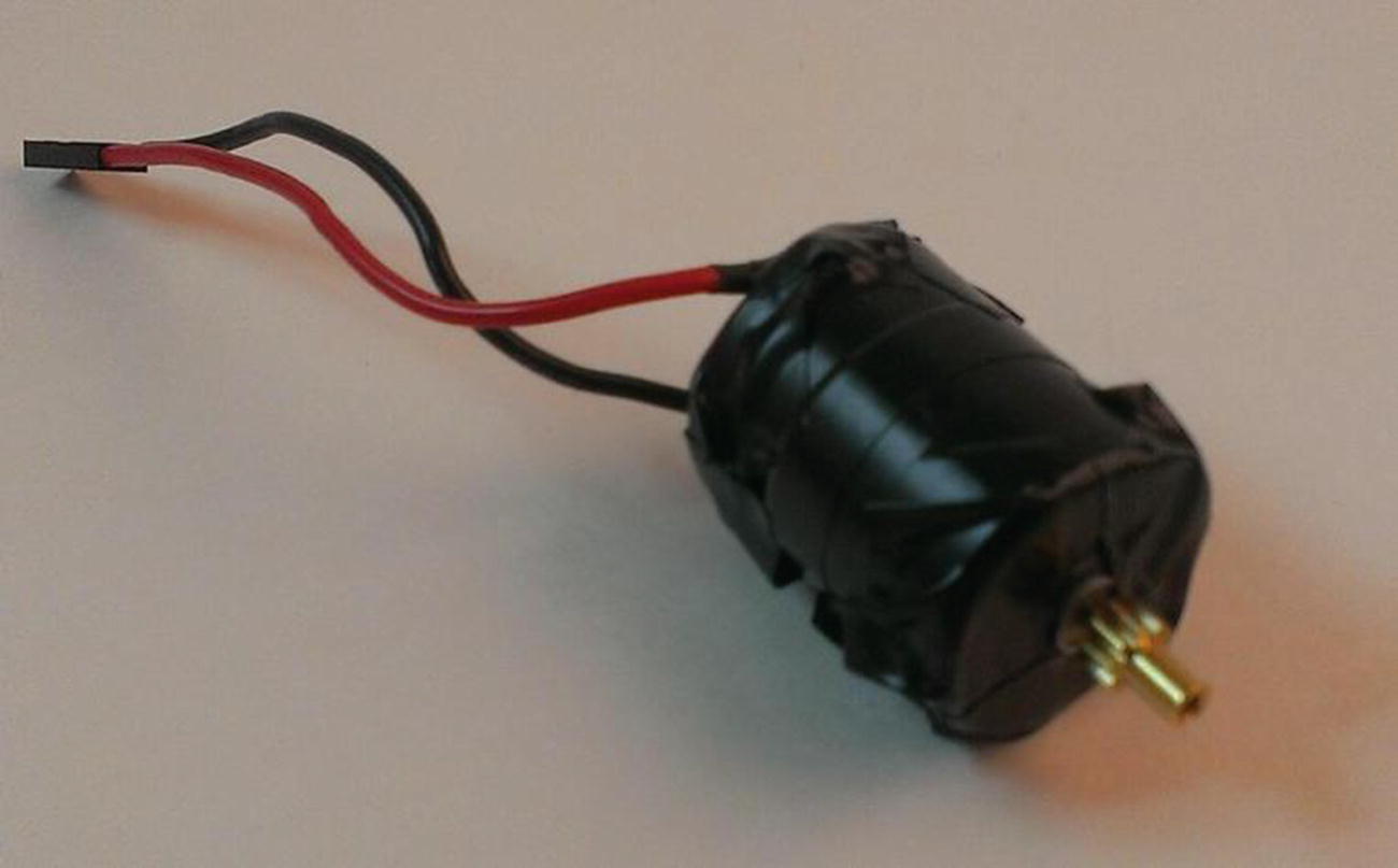
Motor wrapped in electrical tape
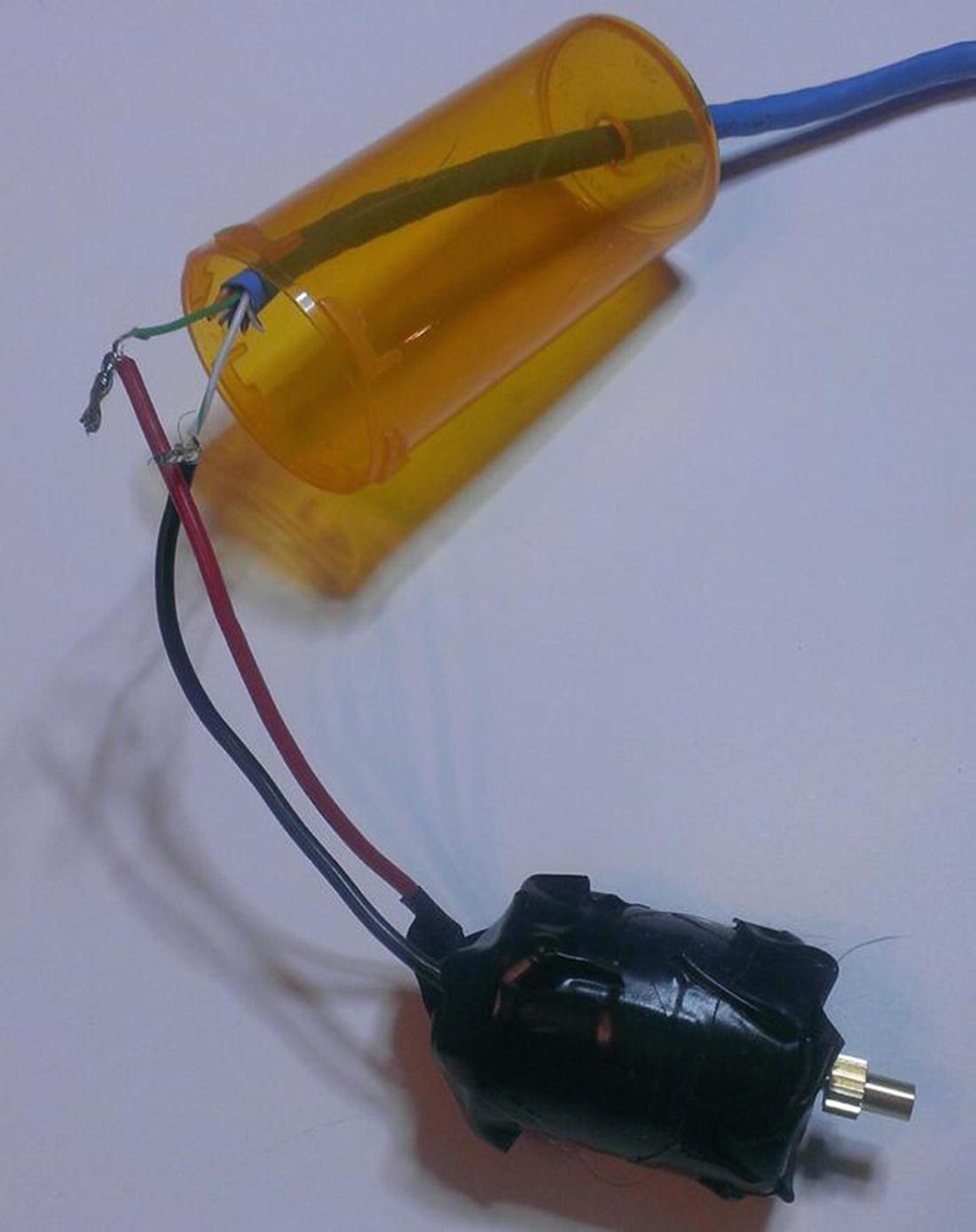
Motor ready to be inserted into pill bottle
Motor snugly fitted in pill bottle
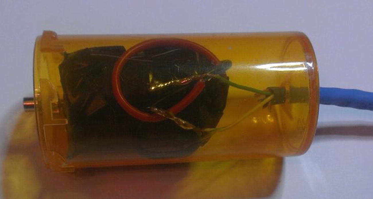
Motor surrounded by wax
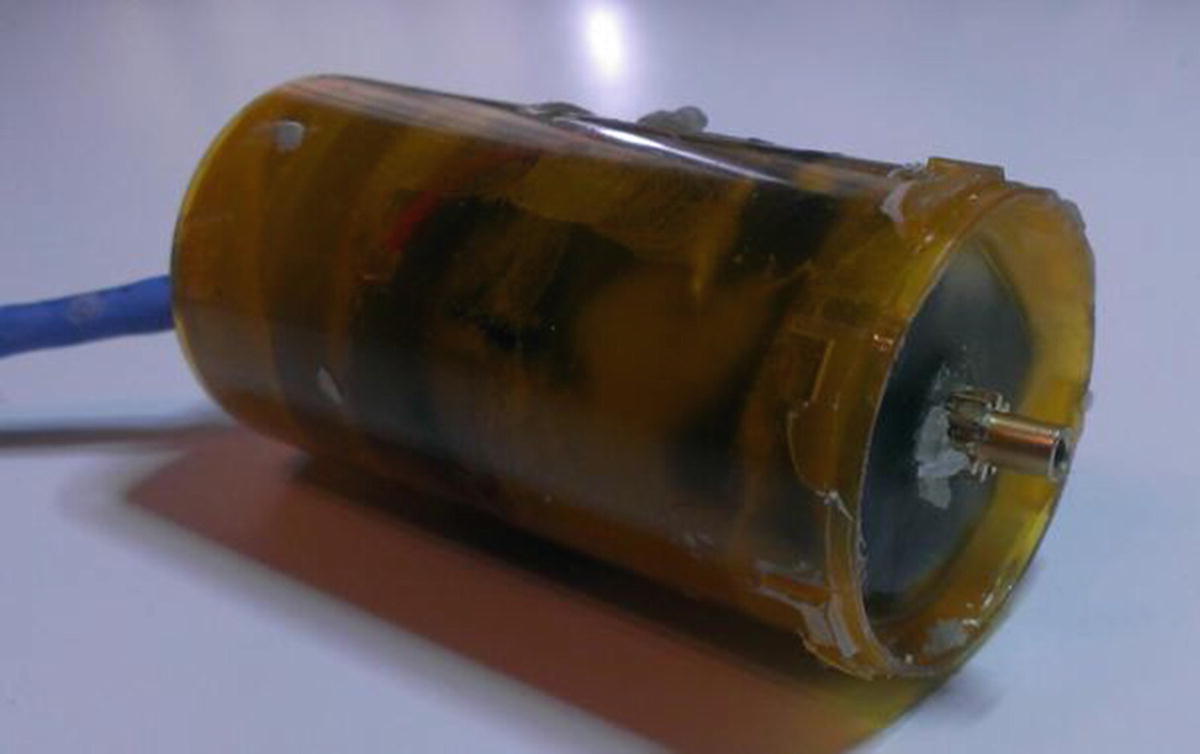
Waterproofed motor, ready for mounting
Connecting the Nunchuk
Since we’re going to be running Ethernet cable from the sub to your nunchuk (which will be kept onboard your boat), you’ll need to use another length of Ethernet cable . Strip the ends, grab four wires, and solder them to your Wiichuck controller. Slide the other end of the cable through the top hole in your sub’s body, then connect the other ends of those four wires to your Pi’s GPIO pins.
Assembling the Final Product
Once your motors are waterproofed, you can assemble the final product. Run the wires from each motor through the holes in your container and connect them to the motor controller board the same way you did for testing. When all the wires have been fed through the holes, use the marine epoxy to seal the holes.
Warning
The 5200 sealant is extremely sticky and messy, and if you get it on your skin, it won’t come off. Wear gloves and do all your work outside if you can. Also, don’t be stingy with the sealant—you’re trying to protect all your electronics, so make sure there’s no way water’s getting into your enclosure.
When the holes are sealed, make sure all your electronic connections are sound and put the Pi and the motor controller into the enclosure. Use a small piece of tape or poster putty (which is what I used) to press the camera against the front “wall” of the enclosure and to hold the various boards in place. Use a small breadboard to connect your grounds, and add your two batteries—one for the Pi and one for the motor controller.
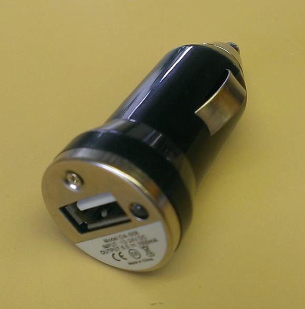
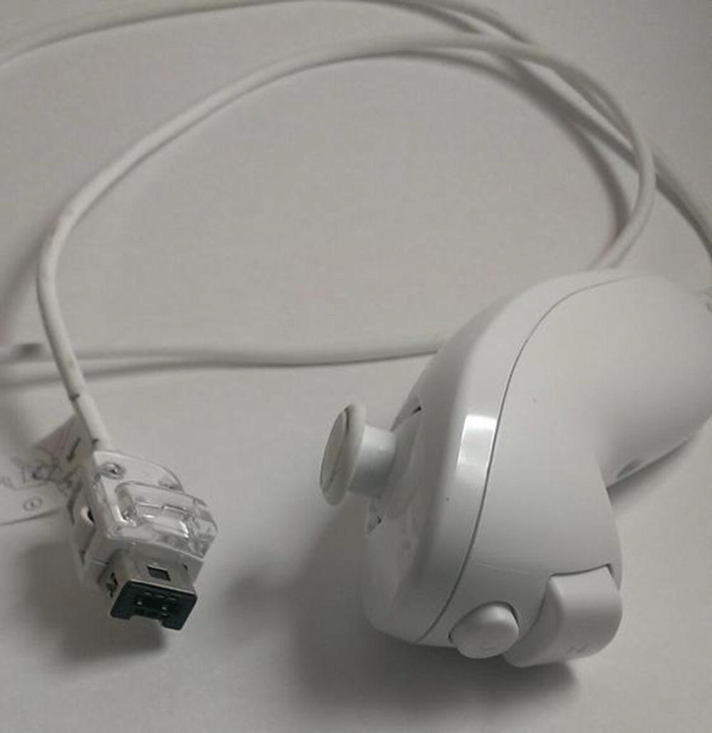
USB car charger
Crack the casing open and use a USB-to-micro-USB cord to attach the USB power out to your Pi’s power in. Then, attach your battery’s power to the charger’s power inputs, and voila! You have 5V powering your Pi!
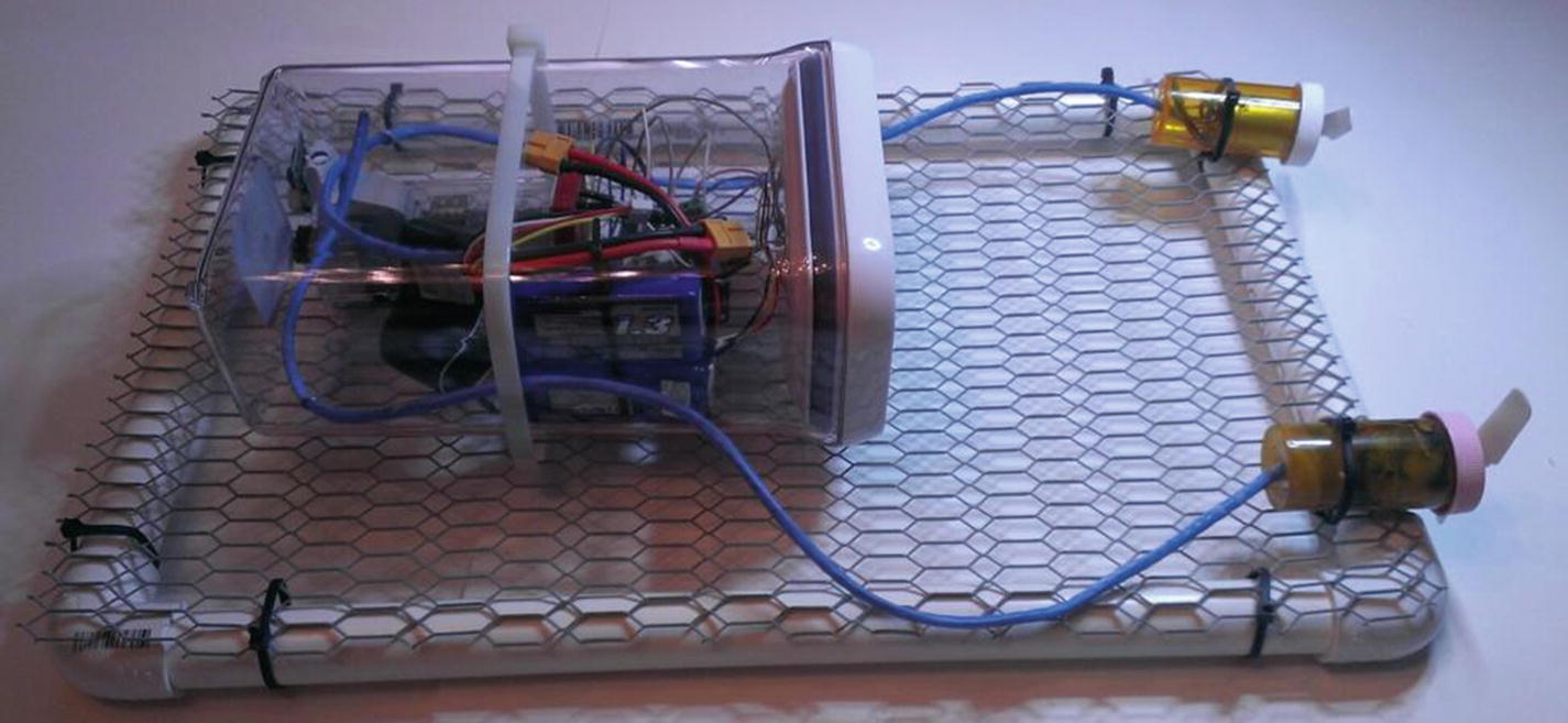
Completed submersible
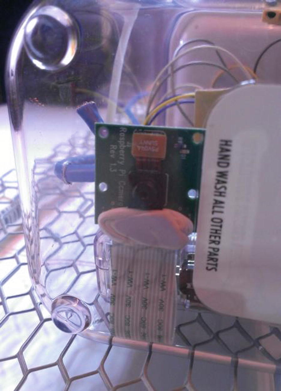
Pi camera placement in enclosure
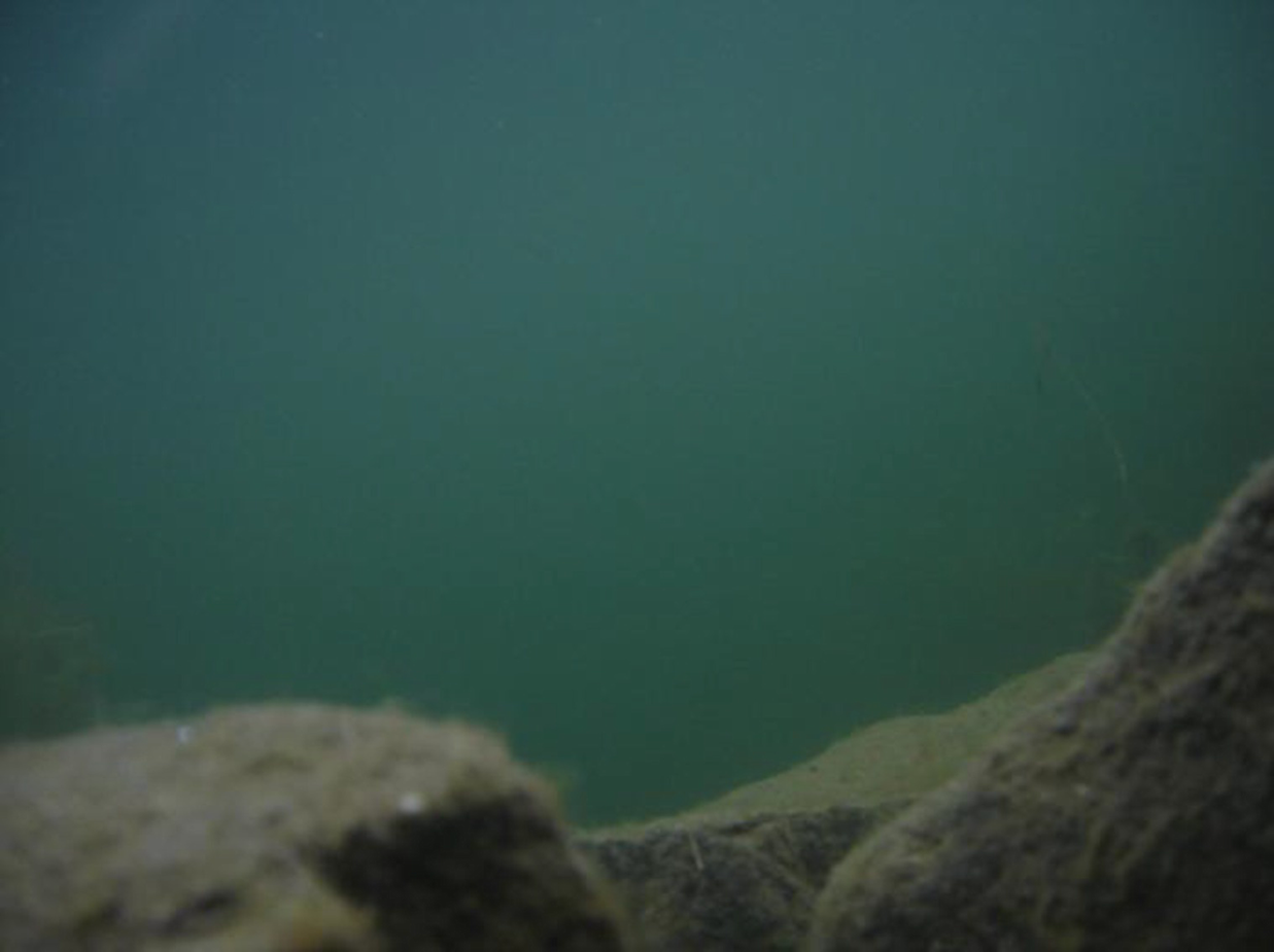
If you’ve followed all the instructions carefully, you should now have a Pi-powered submersible that you can control from onshore or your boat, using a Wii nunchuk. Pressing the button on the nunchuk will let you take pictures, and you can transfer these to your home computer when you bring the Pi back onboard.

Underwater photography
(Full disclosure here: This picture was not taken with a Pi sub. But it could have been.)
Alaskan underwater photography

More Alaskan underwater photography

Underwater pic

Underwater pic

Underwater pic
Enjoy your submarine, and I really would like to see the pictures you take!
Summary
In this chapter, you learned about using the I2C protocol to connect a Wii nunchuk to your Pi and use it to control a few different functions on your Pi. You then constructed a watertight, mobile enclosure for your Pi, connected some motors and your camera, and were able to remotely pilot your sub and take some (hopefully) impressive underwater pictures.
In the next chapter, you’ll learn how to connect a microcontroller—the Arduino—to your Pi to increase its capabilities.