
Peanut butter and jelly. Batman and Robin. Dr. Jekyll and Mr. Hyde. Some things are just meant to go together, and we know it from the moment we first lay eyes on the combination. Such is the case with the Raspberry Pi and the Arduino. Many hobbyists and engineers (including me) had been using the Arduino for projects but were wishing there was a device similar in size with just a bit more power. Well, our wishes were granted with the introduction of the Pi. It has scads more processing power than the Arduino (the Arduino is only a microcontroller), and it has a full ARM processor—four cores’ worth in the new Pi 3. It was obviously a perfect match, and we’ve been using the two together since the Pi made its debut.
Of course, other alternatives to the Arduino exist in the consumer microprocessor-board market. A popular choice is the Beagleboard, an ARM processor–based board that also runs different versions of Linux, including Angstrom and even Ubuntu. However, it’s more like the Pi than the Arduino, and another drawback is its $100 price tag. Parallax puts out a few prosumer-grade boards as well, such as the eight-processor Propeller with a built-in breadboard, but again, it’s more similar to the Pi than the Arduino, and as of this writing costs $129. Its BASIC Stamp line of microcontrollers has been around since the early 1980s, but never got quite the market saturation that Arduino has. Various other boards have made their introduction in the intervening years since the Pi’s intro, with varying degrees of success, such as the Pine64 and the BBC’s micro:bit (which I’ve also written about in another text).
None of these boards, however, have yet gained anywhere near the following of the Arduino. An entire culture has sprung up around this popular little board and the incredible things the average person can do with it. There are many, many books, websites, forums, and groups dedicated to its projects, so I won’t rehash those sources here. However, information on interfacing the Arduino with the Raspberry Pi is a bit scarcer. The Pi is a Linux-based computer, and as such is perfectly capable of running the Arduino software. In this chapter, I’ll walk you through installing that software and creating one or two simple projects that run solely on the Pi and the Arduino—no desktop machine required.
Exploring the Arduino
For those of you unfamiliar with it, the Arduino is a popular implementation of microcontroller technology that is packaged to make it easy for the layperson to program and do complex, interesting tasks with some complex electronics. For people who just want to make stuff, it’s a boon; the Integrated Development Environment (IDE) used to program the Arduino runs on almost any computer, the programming language is very much like C, and—perhaps best of all—the board is inexpensive, with most Arduino versions costing less than $30 US.
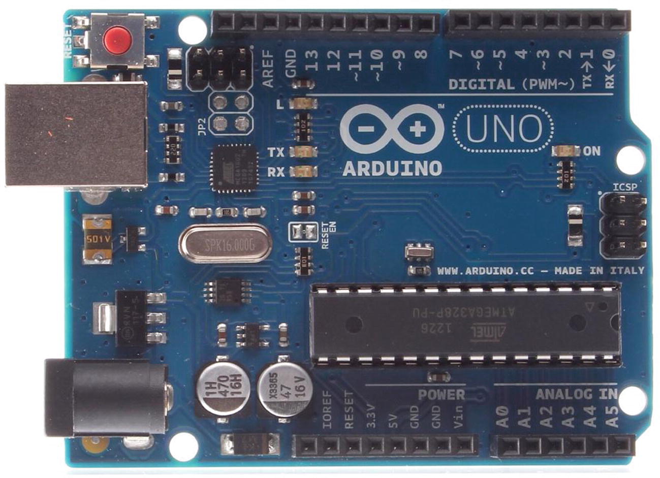
The Arduino Uno
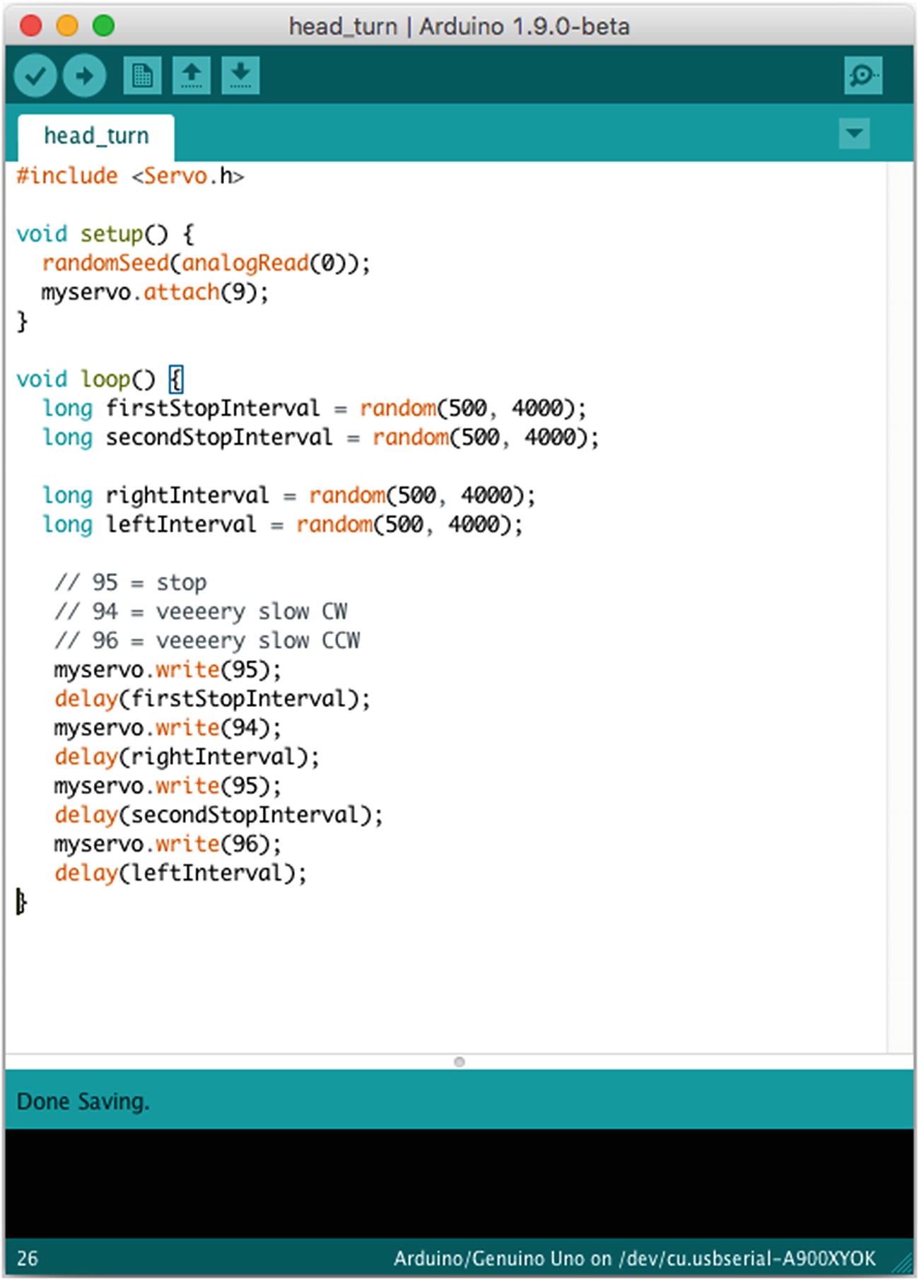
A typical Arduino sketch
In the figure, you can see the code used to interface with a servo; you include the Servo.h library, create a servo object called myservo , and then write values to that object in order to move it. Similarly, to light an LED, for example, you simply set a particular pin to be an output and then send values of “1” or “0” to it to turn a connected LED on or off, respectively. As I mentioned before, you can see that it’s not Python code. Lines are terminated with semicolons, and blocks of code are delineated with brackets, not indentations.
Another nice feature of the Arduino’s setup is that you can pull the Atmega chip off of the board and use it in a standalone breadboarded project. In other words, let’s say you want to design a circuit on the Arduino that will use servos and motors to open and close a pet door in your house. You can write and test the program on your Arduino board, but then you can pull the chip and place it in your standalone circuit. Then, you can replace the chip on the board with another one from Atmega (costing about $3), burn the Arduino bootloader onto the chip, and go on programming. You don’t have to use an entire Arduino every time you design a new circuit.
Installing the Arduino IDE on the Pi
Installing the Arduino IDE on the Pi is a simple matter of opening a command line and typing
You’ll be prompted to accept all of the necessary dependencies, and then the IDE will download and install.
When it finishes, you’ll need to install pyserial—a Python library that makes it easy to communicate with the Arduino through a serial interface. Open your Pi’s Internet browser (the globe icon in the menu bar) and browse to http://sourceforge.net/projects/pyserial/ . Click the “Download” button and save the file. It’s a gzipped tar file, which means you’ll have to unzip and untar it. Back in your terminal, browse to the file’s location (/home/pi/Downloads/) and unzip/untar it by typing
You’ll have a new folder called pyserial-2.7. Navigate into that folder with cd and install the library by typing
Note
The process described in this section is routine when installing a Python-based library. setup.py is a common script used to install a Python library like this, and it requires the install parameter to run. If you’re installing a module that is system wide (in other words, one that doesn’t require you to be in the same directory to run it), inside its unpacked folder you’ll most often find a folder called build and a file called setup.py. You don’t need to do anything with the build folder, because the setup.py script does everything for you. Using sudo (you’ll be changing system-level files, so you need to execute the script as the root user), type sudo python setup.py install into your terminal, and the script will install the module.
The library is now available for your use in any Python script.
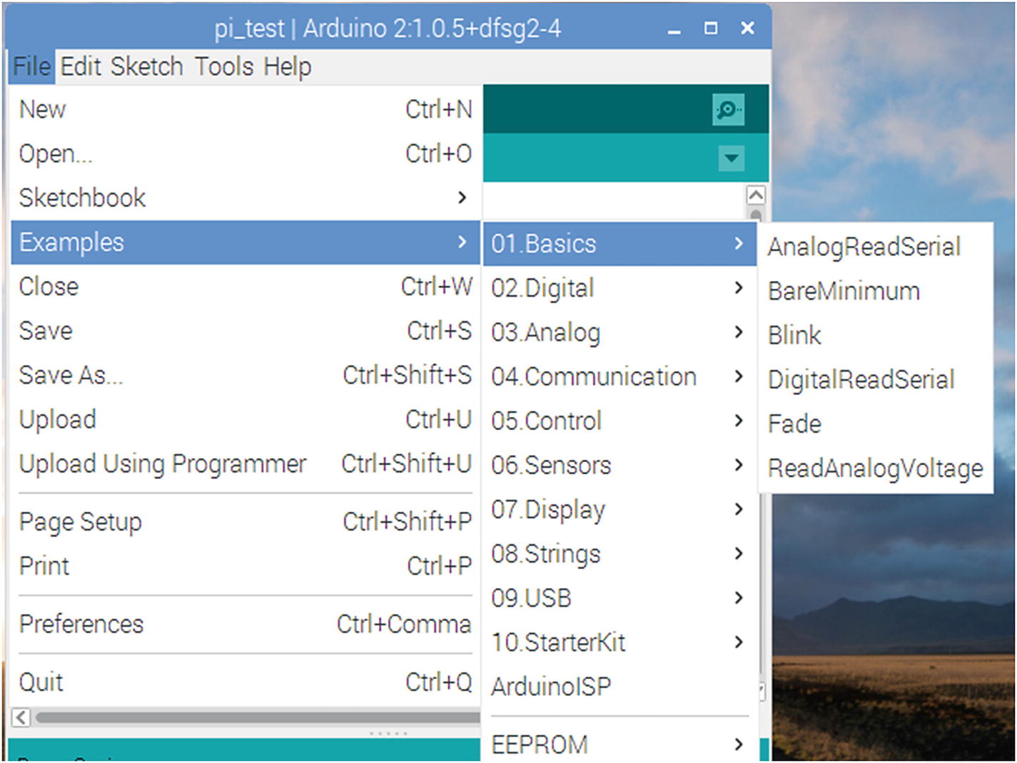
To test it, we’ll have to write some Arduino code. Bear with me, and I’ll walk you through it, since it may be new to you. Open your Arduino IDE (shown in Figure 13-3), and in the sketch window that appears, type the following code:
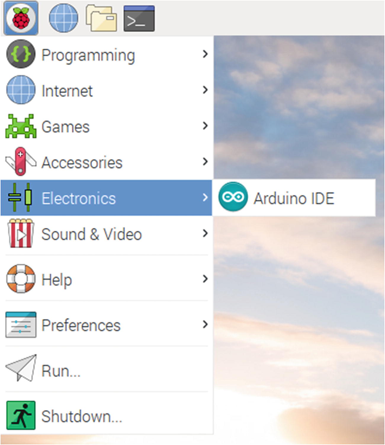
Opening the Arduino IDE on the Pi
The first line of this script sets the variable ledPin to a number, 13. The following setup() function sets pin 13 to be an OUTPUT and then opens communication with the serial port. Finally, the loop() function (which is every Arduino sketch’s main program loop) prints the string "Hello, Raspberry Pi!" to the serial port every 1,000 milliseconds (one second). Save the sketch and name it pi_test.
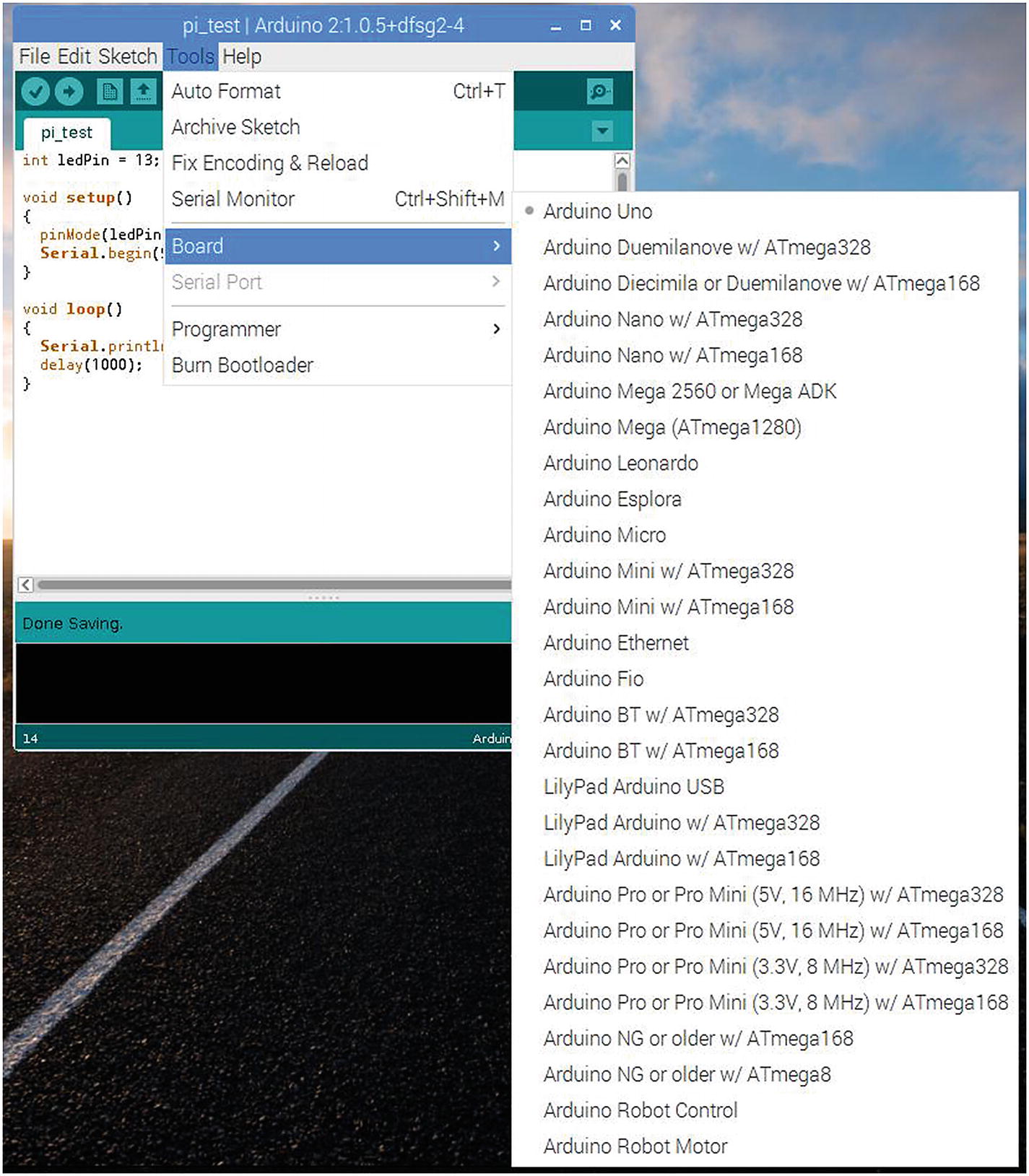
Selecting your Arduino board
Loading the Blink sketch
When the Blink sketch is loaded, select “Upload” from the File menu (or click the right-facing arrow icon in the toolbar) and wait for the IDE to compile the Blink sketch and upload it to your board. When the Arduino window displays “Done uploading,” the red LED on your Arduino should be blinking slowly. If not, double-check your connections and try uploading again. You may get an error message stating that the COM port you selected can’t be found and asking if you want to choose another one. Take note of the suggested port (you’ll use that information later), select it, and upload your sketch.
Once you know that your connection is correct, switch to the pi_test sketch and upload it to the Arduino.
After the sketch has been compiled and uploaded, in a new terminal window, start a Python session and type the following:
Here you’re importing the serial library and starting a communication over the USB0 port at 9600 baud, which is the value we placed in our Arduino code. If you had to use a different port in the connection protocol earlier, use that port instead. For example, you may need to make the second line read
if you had to use the /dev/ttyACM0 port for your connection.
Now we can read from the serial device—the Arduino—which we’ve told to transmit once every second. Continuing in your Python session, type
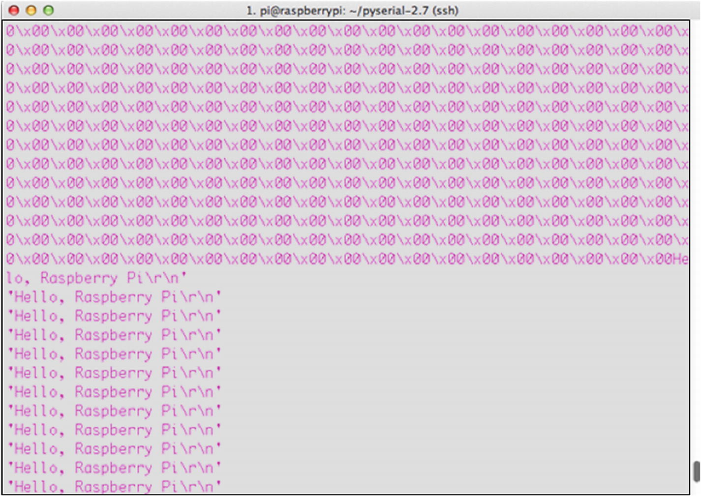
Reading from the Arduino’s serial port
So, we’ve now established that we can read from the Arduino over the serial connection. Let’s establish that we can write to it, as well. Go back to your Arduino pi-test sketch and change the void loop() function to the following:
This code tells the Arduino that if it’s able to read from the serial connection to take the first received integer (the '0') and send it as a parameter to the flash() function, which follows here. After the loop() function, enter the following into your sketch:
This function flashes the Arduino’s onboard LED (hardwired to its pin #13) n number of times, which were passed to it as a parameter. As you can see, the concept is similar to the GPIO’s OUTPUT functionality; first you declare the pin to be an output, and then you write either a HIGH or LOW value to it to turn it on or off. Save the sketch again and re-upload it to your Arduino board. Then, go back to your terminal, and in the same Python session type
You should be rewarded with the Arduino’s onboard LED flashing four times. Try it with different numbers and make sure it’s working. Remember, however, that the Arduino is set up to read only the first integer sent to it. If you type
it will flash once, not 10 times.
Congratulations! You’re now able to read and write to your Arduino from your Raspberry Pi!
Running a Servo
Admittedly, flashing an LED on command is not the most impressive operation you can do with your Arduino/Pi combination. My main goal is to teach you how to get the two devices to communicate, leaving the possible uses and implications up to you, but let’s discuss communicating with a servo connected to your Arduino.
As a matter of fact, all we need to do is modify our LED code just a bit to interface with a servo rather than an LED. Clear the text from your pi_test sketch and replace it with the following:
This code takes the integer you type into your Python prompt, translates it to one speed or another based on its value, and then writes that value to the servo as a speed. To test it, hook your servo’s power wire to the Arduino’s 5V pin, the ground wire to the Arduino’s GND pin, and the signal wire to the Arduino’s pin #9. Then, save the code, upload it to your board, and—again in your Python prompt—experiment with typing different values of
from 0 to 9 into the prompt, and see how the servo responds.
Yes, it’s a very simple code, but hopefully you understand the underlying concepts. Communicating with the Arduino over the Pi’s serial interface is no different from communicating with, say, a GPS unit or another small breakout chip. The Arduino, however, is not only a bit more intelligent, but it is also infinitely more expandable, allowing you to add as many additional parts as the Pi allows, if not more.
Summary
Although this chapter has provided just a short introduction to how to interface the Arduino with your Raspberry Pi, I hope you now realize that communicating with another board like the Arduino, especially via a serial connection, is a simple matter and is no different than communicating with any other device. The main difference, of course, is that you can program the Arduino using its IDE, allowing it to base its actions on information provided to it from the Pi. Likewise, the Arduino can have sensors hooked up to it, act as a sensor network hub, and provide information to the Pi. This can allow you to offload some of the processing power to the Arduino and free up your Pi for more processor-intensive tasks.
In short, the Arduino and the Raspberry Pi don’t compete with other, they complement each other. Each fulfills tasks in a different way, and they can be used together to do neat operations in your projects. Take some time to acquaint yourself with the interface—you’ll be glad you did.