GPIO stands for General-Purpose Input/Output . GPIO pins don’t have fixed assignments, so under program control, they can perform many different tasks. In this chapter, you learn the specifics of the GPIO interface and are introduced to programs that can control devices connected to GPIO pins.
All Raspberry Pi models have GPIO connectors; all except the Pi Zero and Pi Zero W have pin headers that make connections very simple. The Pi Zero and Pi Zero W have open holes that can be used for soldered-in-place GPIO interfaces.
Hardware Used in This Chapter
Raspberry Pi Model B
Raspberry Pi 2
Raspberry Pi 3
Gertboard
PiFace
SunFounder kit
What Can You Do with GPIO?
The number of tasks that can be performed by a Raspberry Pi through its GPIO pins is almost unlimited. Here are a few examples :
Camera control
Motor control
Weather monitoring
Control lights, sounds
Interface and monitor devices
Run Pi without a full-size display
GPIO Pinouts
Although the 26-pin header on the Raspberry Pi Model A and B and the 40-pin header on the A+, B+, Pi 2, and Pi 3 are commonly referred to as the GPIO header, the header also includes leads for 3.3V and 5V DC power, several ground lines, and three specialized types of data leads:
UART
I2C
SPI
Pins that do not fall into one of the preceding categories can be used in a variety of ways under program control. These pins can also be used for GPIO applications if they are not being used for their specialized tasks.
UART
Universal Asynchronous Receive/Transmit pins can be used for serial (one bit at a time) data transmission and receiving. The UART can be used to control GPIO pins or to monitor boot messages transmitted (by default) by the Linux kernel.
I2C
Inter Integrated Circuit pins are often used to communicate with external boards, such as accelerometers like the Adafruit ADXL345.
SPI
Serial Port Interface pins can be used to connect to multiple devices on the same port. Each device is assigned a separate chip select pin.
Figure 9-1 illustrates the default GPIO pinouts for most Raspberry Pi models. Pi 1 Model A and Model B include a 26-pin connection, while other models include a 40-pin connector.
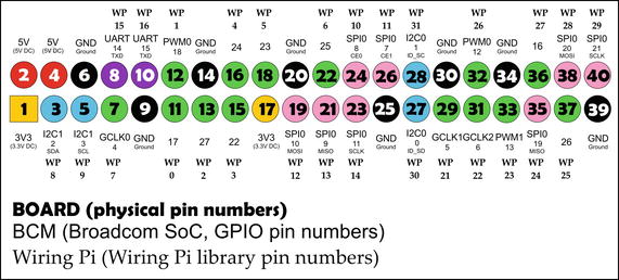
Figure 9-1. The default GPIO pin assignments for Raspberry Pi for BOARD , BCM , and wiringPi numbering schemes
Caution
Revision 1 Pi 1 Models A and B have different default pin assignments. Also, with any version of Raspberry Pi, many pins have alternative uses. For an interactive visual guide to the Raspberry Pi pinout and its variations, visit https://pinout.xyz .
Raspberry Pi GPIO Pin Numbering Schemes
Programs that run on the Raspberry Pi can use any of the following numbering schemes to use particular pins on the PI’s GPIO interface (refer to Figure 9-1):
BOARD
BCM
wiringPi
BOARD
The BOARD numbering scheme identifies pins by their physical pin numbers. A Python program that uses the BOARD numbering scheme includes the following code at the start of the program:
Import RPi.GPIO as GPIOGPIO.setmode(GPIO.BOARD)
The first line imports the RPi.GPIO library, a program module that enables the program to control GPIO channels. The second line specifies that the program uses the BOARD method. The BOARD method is recommended when you are writing a program that might run on various versions of the Raspberry Pi.
Tip
For many more details about referring to GPIO pins in Python programs, see https://sourceforge.net/p/raspberry-gpio-python/wiki/BasicUsage/ .
BCM
The BCM numbering scheme (also known as the GPIO numbering scheme) identifies pins by the channels used by the Broadcom SoC (system on a chip ) processor used on the Raspberry Pi board. A Python program that uses the BCM numbering scheme includes the following code at the start of the program:
Import RPi.GPIO as GPIOGPIO.setmode(GPIO.BCM)
The first line imports the RPi.GPIO library. The second line specifies that the program uses the BCM method. The BCM method is very popular, but a program that uses the BCM method won’t run on different revisions of the Raspberry Pi unless the program checks for the board version and has different commands for pins that vary between versions.
Note
Revision 2 Raspberry Pi boards with a 26-pin GPIO header also have a P5 GPIO connector that is designed for an optional header normally soldered to the underside of the board. The mounting holes are next to the 26-pin connector. To see the pinout for this connector, see the P5 header figure at http://wiringpi.com/pins/ .
wiringPi
The wiringPi numbering scheme was adapted from the Wiring pin numbering scheme used by the Arduino microcontroller board ( www.arduino.cc ). Unlike BCM, wiringPi enables programmers to address logical, rather than physical, pins. In practice, this means that programs written using wiringPi won’t fail when run on differing revisions of Raspberry Pi.
wiringPi uses the C programming language ( www.wiringpi.com ), but it has been adapted for use on Python, Perl, and PHP. To download a version of wiringPi for these languages, see https://github.com/WiringPi . Any Python program that uses wiringPi must include import wiringpi, followed by additional statements that configure the pin numbering method used. For additional code snippets and tips, see https://github.com/WiringPi/WiringPi-Python .
Programming the GPIO Interface
Originally, the C programming language was used to control devices that plugged into the GPIO connector. The first version of the Gertboard (see “Using a Gertboard” in this chapter) included only C language examples, and wiringPi is a library for the C language. However, Python has become a popular choice for educational uses, so many vendors of add-on devices for Raspberry Pi now provide both C and Python sample programs. The program examples in the remainder of this chapter use Python.
Using a Gertboard
The Gertboard (Figure 9-2) includes an Atmel ATmegs 328p AVR microcontroller, relays, digital/analog and analog/digital converters, an LED light array, and open-collector outputs for use with lamps and relays. With its many different types of connectors , it’s a versatile experimentation device. However, the software samples provided with the documentation are designed for the 26-pin Raspberry Pi A and B versions. Due to differences in pinouts and memory locations in later versions of the Raspberry Pi, the Gertboard is not as suitable a choice as newer boards, such as the PiFace Digital ( www.piface.org.uk/ ).
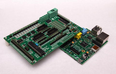
Figure 9-2. The Gertboard mounted on a Raspberry Pi 1 Model B
The Gertboard has a 26-pin connector on its underside that mounts to the 26-pin GPIO connector on the top of the Raspberry Pi (Figure 9-3).
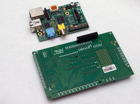
Figure 9-3. The Gertboard’s connector compared to the GPIO pins on the Raspberry Pi Model B
The Gertboard is designed for a wide variety of experiments, all of which require the user to connect jumper blocks or wires to various connectors on the Gertboard. The original Gertboard documentation included only C language examples, but the version 2.0 documentation revision included with later production and also online at www.element14.com/community/docs/DOC-51727/l/assembled-gertboard-user-manual-with-schematics (free membership required) also includes Python versions of most examples.
Tip
The easiest way to use examples for the Gertboard or any other add-on for Raspberry Pi is to download and install the language libraries and examples to a system running Raspbian with PIXEL or another GUI, open the example file in a file manager and run it, and then modify it as desired. You can download the Python version of the software and examples for the Gertboard from http://raspi.tv/downloads . The Gertboard examples include versions for the GPIO and wiringPi libraries.
Figure 9-4 shows the Gertboard configured for the LEDs program (C version: leds. Python with GPIO numbering: leds-rg.py. Python with wiringPi numbering: leds-wp.py). When you run either Python version, the program displays the correct jumper block/wiring positions before starting (Figure 9-5).
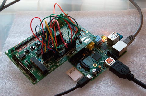
Figure 9-4. The Gertboard running the LEDs test
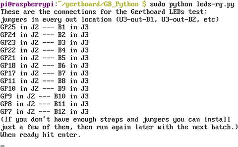
Figure 9-5. Running the GPIO version of the LEDs program for Python
Using a PiFace Control and Display Board
The PiFace Control and Display (PiFace C and D) board was made for the original 26-pin Raspberry Pi 1 Models A and B, but it also works with the newer versions. The PiFace Control and Display 2 board is more suited for use with newer models, as it has been redesigned to avoid being blocked by the additional USB ports on the Pi B+, Pi 2, and Pi 3 boards. However, this author was able to successfully connect the original model to a Pi 2.
As the name implies, the PiFace Control and Display board provides an alternative to a full-size display and keyboard interface. It uses a two-line scrollable LCD display with adjustable contrast. It has a three-position rocker button on the top of the unit (press in the button for a fourth option) and five pushbuttons below the LCD (Figure 9-6).
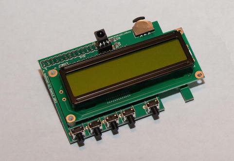
Figure 9-6. The PiFace Control and Display board before being mounted on a Raspberry Pi
To test the PiFace Control and Display board , you can use simple commands that can be run from the Python shell. Figure 9-7 illustrates the commands needed to display the classic “Hello, World!” message. Note that you can program the PiFace C and D board to run with or without the backlight.
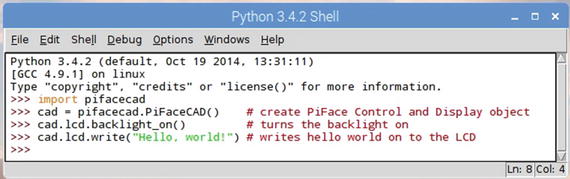
Figure 9-7. Testing the PiFace Control and Display board with commands from the Python shell
The sample programs provided by the PiFace web site and manual take full advantage of the interactive nature of the PiFace C and D and its ability to display custom bitmaps. Figure 9-8 illustrates the author editing the word list in the Hangman sample program , while Figure 9-9 illustrates how the PiFace C and D displays the game in progress.
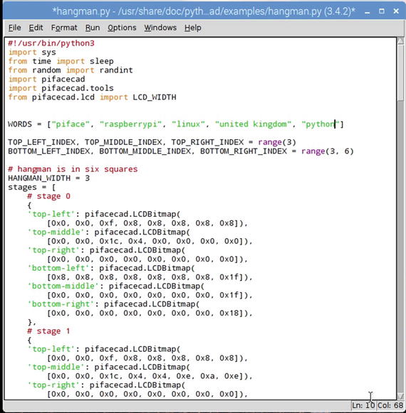
Figure 9-8. Editing the Hangman sample program
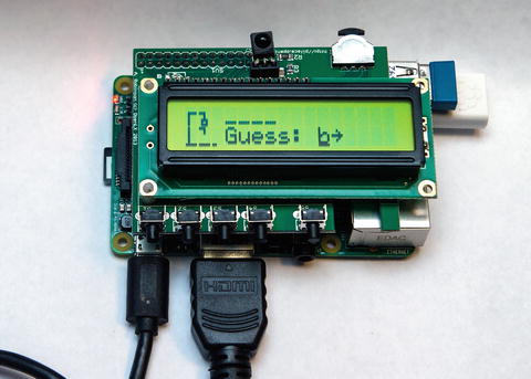
Figure 9-9. Running the Hangman program
Using a Breadboard
One of the most flexible ways to experiment with the Raspberry Pi’s GPIO pins is to connect jumper wires between the Pi and a device, such as an LED, resistor, or a motor. You can accomplish the same result more easily if you attach a device known as a breadboard to a Raspberry Pi’s GPIO pins.
A breadboard (Figure 9-10) has multiple holes for carrying signals between the Raspberry Pi and devices such as resistors, LEDs, motors, small LCD displays, and more. The breadboard illustrated in Figure 9-10 is from the SunFounder Raspberry Pi Super Kit 2.0 , which includes a GPIO extension board (breakout board) and ribbon cable that permit the breadboard to be connected in a variety of ways to the Raspberry Pi. This particular kit also includes many jumper wires, resistors, a motor, switches, control and buffer chips, and many other components for conducting experiments .
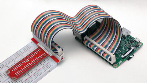
Figure 9-10. Connecting a breadboard to a Raspberry Pi 2
Note
Other vendors with somewhat similar kits include Adafruit ( www.adafruit.com ), CamJam EduKit ( www.thepihut.com ), Monkmakes ( www.monkmakes.com ), and CanaKit ( www.canakit.com ).
Note
To learn more about the kit shown in Figures 9-10 through 9-12, visit www.sunfounder.com/learn/category/Super_Kit_V2_for_RaspberryPi.html . Tutorials (including the following sample code) and kit contents are listed there.
In Figure 9-11, the breadboard is connected to power and signal leads that will send 3.3V to a resistor that is connected to an LED. When the following sample program is run, the LED lights up, then turns off. The pattern repeats until the user kills the program with Ctrl-C. This program (provided by SunFounder) addresses the GPIO pins using the BOARD method .
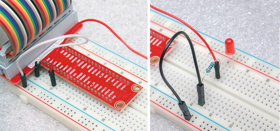
Figure 9-11. The SunFounder breadboard
#!/usr/bin/env pythonimport RPi.GPIO as GPIOimport timeLedPin = 11 # pin11def setup():GPIO.setmode(GPIO.BOARD) # Numbers GPIOs by physical locationGPIO.setup(LedPin, GPIO.OUT) # Set LedPin's mode is outputGPIO.output(LedPin, GPIO.HIGH) # Set LedPin high(+3.3V) to off leddef loop():while True:print '...led on'GPIO.output(LedPin, GPIO.LOW) # led ontime.sleep(0.5)print 'led off...'GPIO.output(LedPin, GPIO.HIGH) # led offtime.sleep(0.5)def destroy():GPIO.output(LedPin, GPIO.HIGH) # led offGPIO.cleanup() # Release resourceif __name__ == '__main__': # Program start from heresetup()try:loop()except KeyboardInterrupt: # When 'Ctrl+C' is pressed, the child program destroy() will be executed.destroy()
In Figure 9-12, the T-connector is located at the other end of the breadboard and is used to connect to a motor (with propeller) and an external power supply. A controller chip connected to the breadboard provides control signals to the motor.
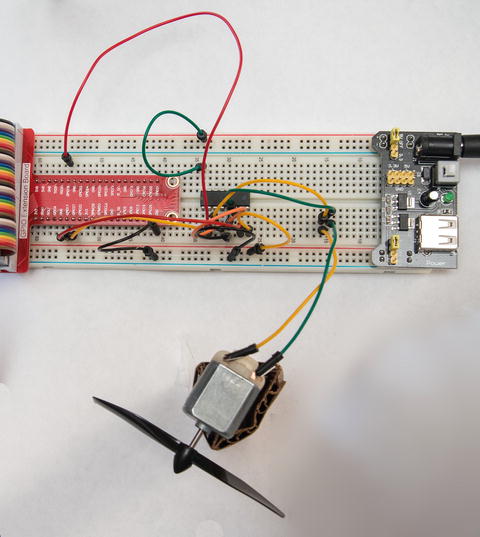
Figure 9-12. Controlling a motor requires an external power supply, a controller chip, and many additional patch cables compared to the LED light setup in Figure 9-11
Here’s the Python program provided by SunFounder for the setup shown in Figure 9-12:
#!/usr/bin/env pythonimport RPi.GPIO as GPIOimport timeMotorPin1 = 11 # pin11MotorPin2 = 12 # pin12MotorEnable = 13 # pin13def setup():GPIO.setmode(GPIO.BOARD) # Numbers GPIOs by physical locationGPIO.setup(MotorPin1, GPIO.OUT) # mode --- outputGPIO.setup(MotorPin2, GPIO.OUT)GPIO.setup(MotorEnable, GPIO.OUT)GPIO.output(MotorEnable, GPIO.LOW) # motor stopdef loop():while True:print 'Press Ctrl+C to end the program...'GPIO.output(MotorEnable, GPIO.HIGH) # motor driver enableGPIO.output(MotorPin1, GPIO.HIGH) # clockwiseGPIO.output(MotorPin2, GPIO.LOW)time.sleep(5)GPIO.output(MotorEnable, GPIO.LOW) # motor stoptime.sleep(5)GPIO.output(MotorEnable, GPIO.HIGH) # motor driver enableGPIO.output(MotorPin1, GPIO.LOW) # anticlockwiseGPIO.output(MotorPin2, GPIO.HIGH)time.sleep(5)GPIO.output(MotorEnable, GPIO.LOW) # motor stoptime.sleep(5)def destroy():GPIO.output(MotorEnable, GPIO.LOW) # motor stopGPIO.cleanup() # Release resourceif __name__ == '__main__': # Program start from heresetup()try:loop()except KeyboardInterrupt: # When 'Ctrl+C' is pressed, the child program destroy() will be executed.destroy()
Regardless of the kit you select, it’s very important to visit the vendor’s web site :
You can download and copy program code rather than typing it in yourself
You may get updated figures to make experiments easier to set up, perform, and modify
In the case of the SunFounder kit, the printed version of the manual showed direct connections between the Pi’s GPIO pins and the breadboard using individual patch wires. However, the web site provides a download that includes updated illustrations that showed how to use the ribbon cable and breakout connector to simplify setups .
Note
SunFounder and other vendors are using the free and open source Fritzing program to create diagrams of their setups. To learn more about Fritzing, see http://fritzing.org/home/ .
Troubleshooting
If you are unable to use a device that connects to the GPIO pins on your Raspberry Pi, check the following:
Have you installed the wiring libraries (BCM or wiringPi) needed? If the libraries are not installed, the program will crash.
If your experiment uses the I2C pins on the Raspberry Pi, are they enabled? Enable them using raspi-config. For more information, see www.raspberrypi-spy.co.uk/2014/11/enabling-the-i2c-interface-on-the-raspberry-pi/ .
Are you running Python (or other language) as superuser (root)?
Check the jumper blocks or cables on your Gertboard or breadboard.
If you need to use an external power supply, make sure it is configured for the correct voltage level. For example, in the motor experiment, 5V DC was needed.
If you use a resistor, make sure it is the correct rating.
If you use a LED lamp, make sure it is connected correctly.
Before you turn on the power, look over everything carefully. Incorrect power connections could fry your experimental devices or your Pi itself.
Summary
The original versions of the Raspberry Pi (Model A and Model B) have 26-pin GPIO pins, while all newer versions have 40-pin GPIO pins or open solder holes (Pi Zero and Pi Zero W).
GPIO (General-Purpose Input/Output) pins can be programmed to perform many different tasks.
Some GPIO pins have primary roles as UART (serial), I2C (inter integrated circuit), and SPI (multiple device serial port), but these pins can also be reassigned through program control.
The BOARD pin numbering scheme identifies GPIO pins by their physical pin locations.
The BCM (GPIO) pin numbering scheme identifies GPIO pins by the channels used by the Broadcom SoC chips that power various Raspberry Pi boards.
The wiringPi pin numbering scheme is based on the Wiring pin numbering scheme used by the Arduino microcontroller board.
The Gertboard includes an Atmel ATmegs 328p AVR microcontroller, relays, digital/analog and analog/digital converters, an LED light array, and open-collector outputs for use with lamps and relays. It is designed for use with the original Raspberry Pi models with the 26-pin GPIO pinout.
The PiFace Control and Display board is available in versions for the 26-pin and current 40-pin GPIO pinout. It includes a two-line scrollable LCD display with a rocker/push button and five pushbuttons.
A breadboard connects to the GPIO pins by means of a ribbon cable and a breakout board. Because the breadboard has the same signals as the GPIO pins, it makes creating circuits easier than connecting directly to the GPIO pins.