
By using the Ethernet port found on most Raspberry Pi models to connect to a network and sharing that connection via wireless, you can provide a stronger signal to computers, printers, multifunction devices, and iOS or Android mobile devices that might otherwise be in “dead spots” for wireless coverage.
For devices that have wired network adapters only or have only outdated Wireless-G or older networking, you can use a wireless adapter on a Pi and share it via a network switch with computers or printers and multifunction devices.
Compared to a dedicated signal booster, the Raspberry Pi is much more versatile. It doesn’t become useless if you install a router with a stronger wireless signal or run Ethernet cable. This chapter shows you how to share a wired or wireless connection.
Note
The default wireless configuration for Raspbian Jessie with PIXEL is to receive an IP address from a DHCP server (typically a router). If you need to assign your Raspberry Pi a static IP address, you need to edit the dhcpcd.conf file. For details, see www.modmypi.com/blog/how-to-give-your-raspberry-pi-a-static-ip-address-update .
Hardware Used in This Chapter
Raspberry Pi 3 OR
Raspberry Pi 2 with Wi-Fi dongle OR
Raspberry Pi Zero W
Gigabit Ethernet (or Fast Ethernet) switch
CAT5e cables
Internet connection
Configuring the Pi for Sharing (Hardware)
In order to share an Internet connection with other devices, a Raspberry Pi needs two different network interfaces:
A wired Ethernet (RJ-45) port
A Wireless-N (802.11n) adapter
The Raspberry Pi 3 includes both, making it the best choice for sharing. However, if you have a Raspberry Pi 2, you have a wired Ethernet port and four USB ports, one of which can be used for a wireless dongle. The Raspberry Pi Zero W has the same wireless hardware as the Raspberry Pi 3, but has only one Micro-USB port. A wired USB to Ethernet adapter can be connected to that port.
Caution
If you want to share a wired connection using a wireless dongle, it must support Access Point or Master mode. Not all wireless dongles do. The official Raspberry Pi USB Wi-Fi dongle ( www.raspberrypi.org/products/usb-wifi-dongle/ ) supports this mode. To learn about others, see http://elinux.org/RPi_USB_Wi-Fi_Adapters for test results. See also http://raspi.tv/2015/new-official-raspberry-pi-wifi-dongle-3-way-testing-vs-thepihut-and-edimax .
To determine the chipset used by a wireless adapter, use ethtool
sudo apt-get install ethtool Ethtool -I displays driver (chipset) information. To see only the driver, use
ethtool -I wlanx |grep driver [x=1-4] See www.raspberrypi.org/forums/viewtopic.php?t=159148&p=1034164 for details.
Configuring the Pi for Sharing (Software)
The packages needed for sharing your Raspberry Pi’s Internet connection with other devices vary with the type of sharing you want to do. Typical packages used for sharing include
hostapd (creates a virtual Wi-Fi access point [AP])
hostap-utils (utilities used by hostapd)
udhcpd (dhcp server; provides dynamic IP addresses)
iw (configures wireless devices)
bridge-utils (wireless bridging utilities)
dnsmasq (DHCP server and DNS server)
network-manager (manages network connections)
isc-dhcp-server (dhcp server)
Many of these packages perform the same or similar tasks, so you will not need all of these in a particular configuration.
With any of these approaches, you will be editing configuration files for wired and wireless network connections, and, in some cases, for NAT (network address translation). Be sure to read carefully through the instructions before you start.
Planning the Network Configuration
No matter which type of Internet connection sharing you set up on your Pi, you might need to determine the range of IP addresses to allocate to clients. If you are using your Pi as an access point, you don’t need to configure this setting, because the Pi is not used as a router or DHCP server. However, if you are using your Pi to share a wireless connection via an Ethernet port and switch with a separate network, you will need to assign a range of IP addresses that are not the same as those assigned by the existing DHCP and router.
For example, if the existing network uses addresses in the 192.168.1.xxx range, the Pi should assign addresses in the 192.168.2.xxx range. The networks will operate separately, but a network bridge enables the newly created 192.168.2.xxx range to connect with the existing network for Internet access.
To share a wired connection wirelessly, you also need to determine the following:
802.11 channel to use
SSID to use
WPA encryption type
WPA encryption key/passphrase
To determine the 802.11 channel to use, use a Wi-Fi monitoring app or program. If you use an Android smartphone or tablet, you can use the Wifi Analyzer (Figure 5-1). The best channels to use with a 2.4GHz wireless adapter, such as the ones built into or designed for use with Raspberry Pi, are 1, 6, or 1l, as the other channels overlap with nearby channels.
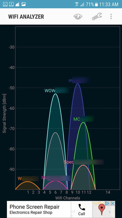
Figure 5-1. In this example, channel 1 has the lowest level of interference from other wireless networks
The SSID , which identifies your wireless network, can be any word or phrase you like. For best security, use an SSID which does not identify your ISP, your name, your location, or your device :
Bad SSID: John’sPi_onMainSt_ABC_ISP
Good SSID: AZ43098
The encryption type, which helps prevent wireless mooching by person or persons unknown, should be WPA2. The only reason to use the older WPA or first-generation, easily hacked WEP is if you are trying to share a connection with devices that should have gone to the boneyard years ago.
Finally, the encryption key should be a good mix of alphanumeric and punctuation characters (up to 60 characters):
Bad encryption key: MynetworkissafeIhope
Good encryption key: My-n07w0511#sa4e90-zz
Record the settings you plan to use, and you’re ready to get started. For the configuration examples in this chapter, we will use the following settings. Be sure to change these as required for your network:
Range of IP addresses to distribute with DHCP: 192.168.2.2-254 (or a subset)
Static IP address to use for Pi as router: 192.168.2.1/255.255.255.0
SSID: Some_Random_Name
Encryption for wireless: WPA2
WPA2 passphrase (key): T32t-1P@00Y
802.11n channel : 1
Sharing a Wired Connection Using a Wireless Adapter
In this scenario , the Raspberry Pi has an Internet connection via Ethernet and also has an on-board or USB wireless adapter. The Pi will be used as an access point for wireless devices to reach the Internet. By working as an access point, the original DHCP server provides IP addresses for the devices that connect to this access point as well to the ones that already connect to the router. Similarly, the original router provides network address translation (NAT) for the devices that connect via the access point as well as those that were already connected to the router. This configuration is considerably simpler than configurations that have the Raspberry Pi provide DHCP and NAT support.
This example is adapted from www.instructables.com/id/How-to-make-a-WiFi-Access-Point-out-of-a-Raspberry/ . These directions have been updated for Raspbian Jessie .
Tip
Commented lines start with a # symbol. I have added additional comments beyond the ones found in the source example to help further explain what the commands do.
Four packages are required:
hostapd
hostap-utils
iw
bridge-utils
Tip
If you need to install more than one package at a time, you can use this syntax (replace package1, etc., with the actual package name): sudo apt-get install package1 package2 package3.
Connect your Raspberry Pi via an Ethernet cable and make sure you can connect to the Internet with it. For example, if you can get updates (Step 2), your Internet connection is working.
Update the list of packages:
sudo apt-get updateInstall the necessary software:
sudo apt-get install hostapd hostap-utils iw bridge-utilsOpen the hostapd file:
sudo nano /etc/init.d/hostapdEdit the line DAEMON_CONF= (see Figure 5-2):
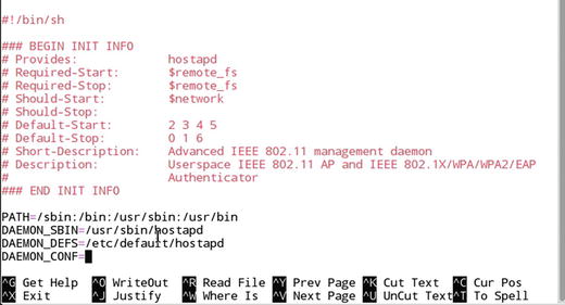
Figure 5-2. The hostapd file before editing
DAEMON_CONF=/etc/hostapd/hostapd.confSave changes (Ctrl-O, press the Enter key) and exit (Ctrl-X) (see Figure 5-3).
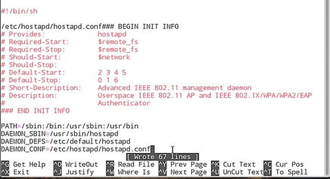
Figure 5-3. The hostapd file after editing
Create hostapd.conf. If the file does not already exist, the following command opens up a blank file :
sudo nano /etc/hostapd/hostapd.confAdd the following to the hostapd.conf file:
ctrl_interface=/var/run/hostapd################################ Basic Config###############################macaddr_acl=0 auth_algs=1# Most modern wireless drivers in the kernel need driver=nl80211driver=nl80211########################### Local configuration...##########################interface=wlan0bridge=br0hw_mode=gieee80211n=1channel=1 #Use a channel that is the least congestedssid=Some_Random_Name #Not the same as your existing WLAN's SSIDmacaddr_acl=0auth_algs=1ignore_broadcast_ssid=0wpa=3wpa_passphrase=T32t-1P@00Y #Replace with your preferred passphrasewpa_key_mgmt=WPA-PSK#wpa_pairwise=TKIP #Uncomment this line to support WPA encryptionrsn_pairwise=CCMP #This line supports WPA2 encryption### Following recommended for use with R Pi 3 or Pi Zero W's onboard Wi-Fiwmm_enabled=1 # QoS supportht_capab=[HT40][SHORT-GI-20][DSSS_CCK-40]#[HT40]support for 20 and 40MHz channels#[SHORT-GI-20]support for short guard interval for 20MHz channels#[DSSS_CCK-40]support for 40MHz data ratesNote Step 8 provides the instructions to create a WPA2-secured network. You can also set up an open (unsecured) network in this step by omitting the lines that begin with wpa=, wpa_passphrase=, wpa_key_mgmt=, rsn_pairwise=, and wpa_pairwise=.
Save changes (Ctrl-O, press the Enter key) and exit(Ctrl-X).
Open the /etc/network/interfaces file:
sudo nano /etc/network/interfacesConfigure the network bridge by adding the following lines to the beginning of the file if not already present:
auto loiface lo inet loopbackauto br0 #br0 is the bridgeiface br0 inet staticaddress 192.168.1.11netmask 255.255.255.0network 192.168.1.0broadcast 192.168.1.255gateway 192.168.1.1bridge-ports eth0 wlan0 #bridges the Ethernet port to Wi-FiSave changes (Ctrl-O, press the Enter key) and exit (Ctrl-X).
Reboot the Raspberry Pi. When you log back in, your repeater should be running and ready to extend your network .
Sharing a Wireless Connection Using an Ethernet Port and Switch
If you want to create a separate network that can still access the Internet, you can share a Raspberry Pi’s wireless network by using its built-in Ethernet port along with an Ethernet switch. Because you are connecting two networks together, you will need to create routing tables on the Pi. The following is based on https://raspberrypi.stackexchange.com/questions/48307/sharing-the-pis-wifi-connection-through-the-ethernet-port . I have added illustrations, comments, and clarifications.
One package needs to be installed:
dnsmasq
Files to edit :
/etc/network/interfaces (configures wireless and Ethernet interfaces)
/etc/dnsmasq.conf (configures dns masquerading)
/etc/sysctl.conf (enables packet forwarding)
/etc/iptables (via save commands from command line, not nano; configures IP routing tables)
/etc/rc.local (restores routing tables)
Connect an Ethernet switch to the RPi’s Ethernet port with a standard CAT5e or better cable (not a crossover cable). The Pi’s Ethernet port supports 10/100Mbps Ethernet speeds, so a Fast Ethernet switch is sufficient. However, a Gigabit Ethernet switch (10/100/1000Mbps) is also suitable.
Connect a second Ethernet cable between the switch and a PC .
Start the RPi and log into it.
Enter sudo apt-get update.
Enter sudo apt-get install dnsmasq.
Use sudo nano /etc/network/interfaces to edit the interfaces file. If you prefer a different editor, substitute it for nano in the commands in this section.
Add these lines to the eth0 section:
allow-hotplug eth0iface eth0 inet staticaddress 192.168.2.1netmask 255.255.255.0network 192.168.2.0broadcast 192.168.2.255Save changes and exit (Ctrl-O, press the Enter key, and Ctrl-X).
Move the original dnsmasq.conf file:
sudo mv /etc/dnsmasq.conf /etc/dnsmasq.conf.origCreate and edit a new (blank) version of dnsmasq.conf:
sudo nano /etc/dnsmasq.confAdd the following lines (# indicates an optional comment ; see Figure 5-4):
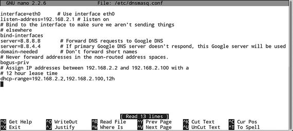
Figure 5-4. The dnsmasq.conf file after editing
interface=eth0 # Use interface eth0listen-address=192.168.2.1 # listen on# Bind to the interface to make sure we aren't sending things# elsewherebind-interfacesserver=8.8.8.8 # Forward DNS requests to Google DNSserver=8.8.4.4 # Secondary Google DNS serverdomain-needed # Don't forward short names# Never forward addresses in the nonrouted address spaces.bogus-priv# Assign IP addresses between 192.168.2.2 and 192.168.2.100 with a# 12 hour lease timedhcp-range=192.168.2.2,192.168.2.100,12hSave changes and exit (Ctrl-O, press the Enter key, and Ctrl-X).
Note The original version of this file didn’t include a second DNS server. Having at least two DNS servers is good practice, as the secondary server will be used if the primary server fails.
Edit the /etc/sysctl.conf file to enable packet forwarding:
sudo nano /etc/sysctl.confRemove the # from the beginning of the line containing net.ipv4.ip_forward=1. The line before editing:
#net.ipv4.ip_forward=1The line after editing:
net.ipv4.ip_forward=1Network address translation (NAT) is used to connect the wireless LAN (wlan0) on the Raspberry Pi with the devices that connect via Ethernet (eth0) and a switch. Use the following command to set up NAT :
sudo iptables -t nat -A POSTROUTING -o wlan0 -j MASQUERADEsudo iptables -A FORWARD -i wlan0 -o eth0 -m state --state RELATED,ESTABLISHED -j ACCEPTsudo iptables -A FORWARD -i eth0 -o wlan0 -j ACCEPTTip iptables terms and syntax to know
POSTROUTING: altering packets as they leave
MASQUERADE: used for network address translation (NAT)
FORWARD: sending data
RELATED: new connection from a packet that is associated with an existing connection
ESTABLISHED: data packet is associated with a connection that has sent and received data
ACCEPT: packet allowed through
-j: jumps to specified action (a.k.a. “target”) when packet matches a particular rule
-t: specifies table name
-o: outgoing network interface to use for a rule
-A: appends iptable to end of specified chain of rules
-m: loads match option module by specified name
-I: specifies the network interface used for incoming traffic
The following command creates a file that saves the rules for reuse:
sudo sh -c "iptables-save > /etc/iptables.ipv4.nat"To enable the rules to be used automatically when the system reboots, edit /etc/rc.local and add iptables-restore < /etc/iptables.ipv4.nat near the end of the file:
sudo nano /etc/rc.localEnd of file before editing:
exit 0End of file after editing:
iptables-restore < /etc/iptables.ipv4.natexit 0Restart the Raspberry Pi:
sudo rebootAfter rebooting , you can view the routing tables (Figure 5-5) with route
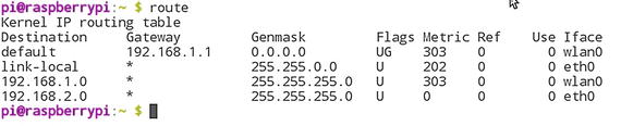
Figure 5-5. A properly configured routing table . The Raspberry Pi’s wireless (wlan0) connection is using the 192.168.1.x range, while the Ethernet (eth0) connection is usig the 192.168.2.x range.
To test the connection, use the PC connected to the second Ethernet cable and run a ping command such as ping 192.168.2.1 (Figure 5-6):
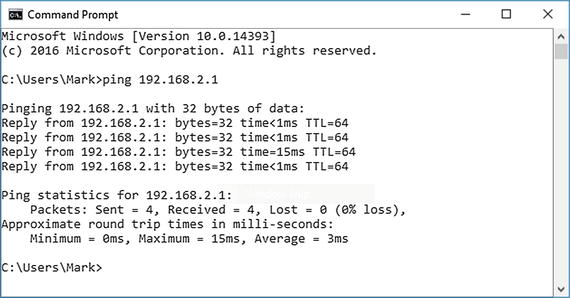
Figure 5-6. A successful ping command receives replies back from the IP address set up on the Raspberry Pi for sharing
Troubleshooting
To help prevent (and fix) problems you might encounter when working with existing or new procedures for Internet sharing, keep the following tips in mind:
Use ipconfig or ifconfig to check IP addresses on your client PCs. If a system that is supposed to get an IP address from a DHCP server (router or Raspberry Pi) has a 169.254.x.x address, it is not receiving an IP address. Run ifconfig on the Raspberry Pi to determine if it is properly configured.
Use route to view the routing tables created by iptables. If you don’t see results similar to those in Figure 5-5, odds are you won’t be able to connect to the Internet. Recheck your file commands for eth0, wlan0, and bridging.
A bad Ethernet port or cable can cause sharing to fail. Look for activity lights on each cable connected to a Raspberry Pi or device that is active. Lack of activity lights suggests a problem. Swap ports or cables to find the problem. Keep in mind that both ends of the cable need to be connected to running devices to display activity lights .
Tip
Understanding Autoconfiguration addresses
The 169.254.x.x address is an autoconfiguration address that is used only if a system set to receive an IP address automatically cannot connect to a DHCP server. Compare existing IP address ranges and make sure that the Raspberry Pi is using a different IP address range. Also, be sure to check switch and cable power and connections.
Summary
To share an Internet connection, your Raspberry Pi needs both a wireless adapter and an Ethernet port. The Raspberry Pi 3 has both, but with most other models, you will need to add a wireless adapter. The Pi Zero has neither type of adapter, while the Pi Zero W has a wireless adapter, but no Ethernet port.
Depending upon whether you are sharing a wireless or wired connection, you can use a variety of packages available for Raspbian Jessie (PIXEL or Lite versions).
Before you start, plan your network configuration by determining the IP address range(s) already in use on your network. If you are sharing a wired connection wirelessly, you also need to determine wireless settings to use, such as 802.11 channel, SSID, and encryption settings.
If you want to share a wireless connection, your Raspberry Pi will need not only an Ethernet port (or USB to Ethernet adapter), but also an Ethernet switch.