Table of Contents for
Unity in Action, Second Edition
 Unity in Action, Second Edition
Published by
Manning Publications, 2018
Unity in Action, Second Edition
Published by
Manning Publications, 2018
- Cover
- Unity in Action
- Praise for the First Edition
- Titlepage
- Copyright
- foreword
- preface
- acknowledgments
- about this book
- about the author
- about the cover illustration
- Part 1: First steps
- Chapter 1: Getting to know Unity
- Chapter 2: Building a demo that puts you in 3D space
- Chapter 3: Adding enemies and projectiles to the 3D game
- Chapter 4: Developing graphics for your game
- Part 2: Getting comfortable
- Chapter 5: Building a Memory game using Unity’s 2D functionality
- Chapter 6: Creating a basic 2D platformer
- Chapter 7: Putting a GUI onto a game
- Chapter 8: Creating a third-person 3D game: player movement and animation
- Chapter 9: Adding interactive devices and items within the game
- Part 3: Strong finish
- Chapter 10: Connecting your game to the internet
- Chapter 11: Playing audio: sound effects and music
- Chapter 12: Putting the parts together into a complete game
- Chapter 13: Deploying your game to players’ devices
- afterword
- Appendix A: Scene navigation and keyboard shortcuts
- Appendix B: External tools used alongside Unity
- Appendix C: Modeling a bench in Blender
- Appendix D: Online learning resources
- Index
4
Developing graphics for your game
- Understanding art assets
- Understanding whiteboxing
- Using 2D images in Unity
- Importing custom 3D models
- Building particle effects
We’ve been focusing mostly on how the game functions and not as much on how the game looks. That was no accident—this book is mostly about programming games in Unity. Still, it’s important to understand how to work on and improve the visuals. Before we get back to the book’s main focus on coding different parts of the game, let’s spend a chapter learning about game art so that your projects won’t always end up with just blank boxes sliding around.
All of the visual content in a game is made up of what are called art assets. But what exactly does that mean?
4.1 Understanding art assets
An art asset is an individual unit of visual information (usually a file) used by the game. It’s an overarching umbrella term for all visual content; image files are art assets, 3D models are art assets, and so on. Indeed, the term art asset is simply a specific case of an asset, which you’ve learned is any file used by the game (such as a script)—hence the main Assets folder in Unity. Table 4.1 lists and describes the five main kinds of art assets used in building a game.
Creating art for a new game generally starts with either 2D images or 3D models because those assets form a base on which everything else relies. As the names imply, 2D images are the foundation of 2D graphics, whereas 3D models are the foundation of 3D graphics. Specifically, 2D images are flat pictures; even if you have no previous familiarity with game art, you’re probably already familiar with 2D images from the graphics used on websites. Three-dimensional models, on the other hand, may need to be defined for a newcomer.
The next two types of assets on the list are materials and animations. Unlike 2D images and 3D models, materials and animations don’t do anything in isolation and are much harder for newcomers to understand. 2D images and 3D models are easily understood through real-world analogs: paintings for the former, sculptures for the latter. Materials and animations aren’t as directly relatable to the real world. Instead, both are abstract packets of information that layer onto 3D models. In fact, materials were already introduced in a basic sense in chapter 3.
Continuing the art analogy, you can think of a material as the medium (clay, brass, marble, and so on) that the sculpture is made of. Similarly, an animation is also an abstract layer of information that’s attached to a visible object.
For a concrete example, think about a character walking around. The overall position of the character is handled by the game’s code (for example, the movement scripts you wrote in chapter 2). But the detailed movements of feet hitting the ground, arms swinging, and hips rotating are an animation sequence that’s being played back; that animation sequence is an art asset.
To help you understand how animations and 3D models relate, let’s make an analogy with puppeteering: the 3D model is the puppet, the animator is the puppeteer who makes the puppet move, and the animation is a recording of the puppet’s movements. The movements defined this way are created ahead of time and are usually small-scale movements that don’t change the overall positioning of the object. This is in contrast to the sort of large-scale movements that were done in code in previous chapters. The final kind of art asset from table 4.1 is a particle system.
Particle systems are useful for creating visual effects, like fire, smoke, or spraying water. The particles (that is, the individual objects under the control of a particle system) can be any mesh object that you choose, but for most effects the particles will be a square displaying a picture (a flame spark or a smoke puff, for example).
Much of the work of creating game art is done in external software, not within Unity itself. Materials and particle systems are created within Unity, but the other art assets are created using external software. Refer to appendix B to learn more about external tools; a variety of art applications are used for creating 3D models and animation. 3D models created in an external tool are then saved as an art asset that’s imported by Unity. I use Blender when explaining how to model in appendix C (download it from www.blender.org/), but that’s just because Blender is open source and thus available to all readers.
As you work through the project for this chapter, you’ll see examples of most of these types of art assets (animations are a bit too complex for now and will be addressed later in the book). You’re going to build a scene that uses 2D images, 3D models, materials, and a particle system. In some cases, you’ll bring in already existing art assets and learn how to import them into Unity, but at other times (especially with the particle system) you’ll create the art asset from scratch within Unity.
This chapter only scratches the surface of game art creation. Because this book focuses on how to program in Unity, extensive coverage of art disciplines would reduce how much the book could cover. Creating game art is a giant topic in and of itself, easily able to fill several books. In most cases, a game programmer would need to partner with a game artist who specializes in that discipline. That said, it’s extremely useful for game programmers to understand how Unity works with art assets and possibly even create their own rough stand-ins to be replaced later (commonly known as programmer art).
4.2 Building basic 3D scenery: whiteboxing
The first content creation topic we’ll go over is whiteboxing. This process is usually the first step in building a level on the computer (after designing the level on paper). As the name implies, you block out the walls of the scene with blank geometry (that is, white boxes). Looking at the list of different art assets, this blank scenery is the most basic sort of 3D model, and it provides a base on which to display 2D images. If you think back to the primitive scene you created in chapter 2, that was basically whiteboxing (you just hadn’t learned the term yet). Some of this section will be a rehash of work done in the beginning of chapter 2, but we’ll cover the process a lot faster this time, as well as discussing more new terminology.
4.2.1 Whiteboxing explained
Blocking out the scene with blank geometry serves a couple of purposes. First, this process enables you to quickly build a sketch that will be progressively refined over time. This activity is closely associated with level design and/or level designers.
As game development teams have grown in size and team members have become more specialized, a common level-building workflow is for the level designer to create a first version of the level through whiteboxing. This rough level is then handed over to the art team for visual polish. But even on a tiny team, where the same person is both designing levels and creating art for the game, this workflow of first doing whiteboxing and then polishing the visuals generally works best; you have to start somewhere, after all, and whiteboxing gives a clear foundation on which to build up the visuals.
A second purpose served by whiteboxing is that the level reaches a playable state very quickly. It may not be finished (indeed, a level right after whiteboxing is far from finished), but this rough version is functional and can support gameplay. At a minimum, the player can walk around the scene (think of the demo from chapter 2). In this way, you can test to make sure the level is coming together well (for example, are the rooms the right size for this game?) before investing a lot of time and energy in detailed work. If something is off (say you realize the spaces need to be bigger), then it’s much easier to change and retest while you’re at the whiteboxing stage.
Moreover, being able to play the under-construction level is a huge morale boost. Don’t discount this benefit: Building all the visuals for a scene can take a great deal of time, and it can start to feel like a slog if you have to wait a long time before you can experience any of that work in the game. Whiteboxing builds a complete (if primitive) level right away, and it’s exciting to then play the game as it continually improves.
All right, so you understand why levels start with whiteboxing; now let’s build a level!
4.2.2 Drawing a floor plan for the level
Building a level on the computer follows designing the level on paper. We’re not going to get into a huge discussion about level design; just as chapter 2 noted about game design, level design (which is a subset of game design) is a large discipline that could fill an entire book by itself. For our purposes, we’re going to draw a basic level, with little design going into the plan, in order to give us a target to work toward.
Figure 4.1 is a top-down drawing of a simple layout with four rooms connected by a central hallway. That’s all we need for a plan right now: a bunch of separated areas and interior walls to place. In a real game, your plan would be more extensive and include things like enemies and items.
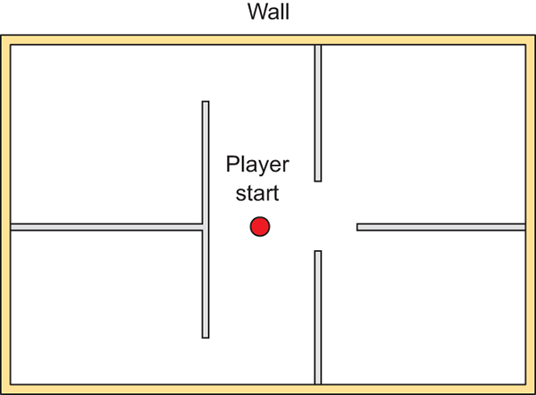
Figure 4.1 Floor plan for the level: four rooms and a central corridor
You could practice whiteboxing by building this floor plan, or you could draw your own simple level to practice that step, too. The specifics of the room layout matters little for this exercise. The important thing for our purposes is to have a floor plan drawn so that we can move forward with the next step.
4.2.3 Laying out primitives according to the plan
Building the whitebox level in accordance with the drawn floor plan involves positioning and scaling a bunch of blank boxes to be the walls in the diagram. As described in section 2.2.1, select GameObject > 3D Object > Cube to create a blank box that you can position and scale as needed.
The first object will be the floor of the scene; in the Inspector, rename the object and lower it to -.5 Y in order to account for the height of the box itself (figure 4.2 depicts this). Then stretch the object along the X- and Z-axes.
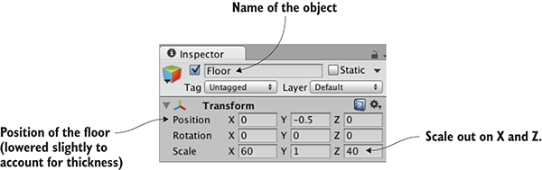
Figure 4.2 Inspector view of the box positioned and scaled for the floor
Repeat these steps to create the walls of the scene. You probably want to clean up the Hierarchy view by making walls children of a common base object (remember, position the root object at 0, 0, 0, and then drag objects onto it in Hierarchy), but that’s not required. Also put a few simple lights around the scene so that you can see it; referring to chapter 2, create lights by selecting them in the Light submenu of the GameObject menu. The level should look something like figure 4.3 once you’re done with whiteboxing.
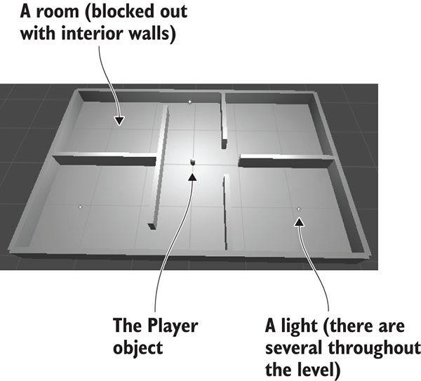
Figure 4.3 Whitebox level of the floor plan in figure 4.1
Set up your player object or camera to move around (create the player with a character controller and movement scripts; refer to chapter 2 if you need a full explanation). Now you can walk around the primitive scene in order to experience your work and test it out. And that’s how you do whiteboxing! Pretty simple—but all you have right now is blank geometry, so let’s dress up the geometry with pictures on the walls.
4.3 Texture the scene with 2D images
The level at this point is a rough sketch. It’s playable, but clearly a lot more work needs to be done on the visual appearance of the scene. The next step in improving the look of the level is applying textures.
Textures have a number of uses in 3D graphics, but the most straightforward use is to be displayed on the surface of 3D models. Later in this chapter, we’ll discuss how this works for more complex models, but for our whiteboxed level, the 2D images will act as wallpaper covering the walls (see figure 4.4).
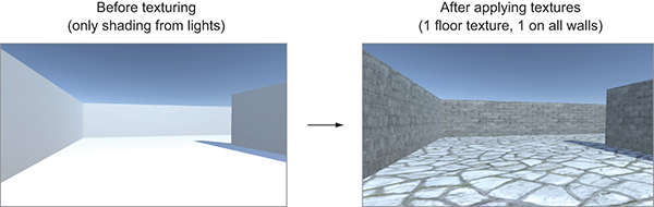
Figure 4.4 Comparing the level before and after textures
As you can see from the comparison in figure 4.4, textures turn what was an obviously unreal digital construct into a brick wall. Other uses for textures include masks to cut out shapes and normal maps to make surfaces bumpy. Later, you may want to look up more information about textures in the resources mentioned in appendix D.
4.3.1 Choosing a file format
A variety of file formats is available for saving 2D images, so which should you use? Unity supports the use of many different file formats, so you could choose any of the ones shown in table 4.2.
| File type | Pros and cons |
| PNG | Commonly used on the web. Lossless compression; has an alpha channel. |
| JPG | Commonly used on the web. Lossy compression; no alpha channel. |
| GIF | Commonly used on the web. Lossy compression; no alpha channel. (Technically, the loss isn’t from compression; rather, data is lost when the image is converted to 8-bit. Ultimately, it amounts to the same thing.) |
| BMP | Default image format on Windows. No compression; no alpha channel. |
| TGA | Commonly used for 3D graphics; obscure everywhere else. No or lossless compression; has an alpha channel. |
| TIFF | Commonly used for digital photography and publishing. No or lossless compression; no alpha channel. |
| PICT | Default image format on old Macs. Lossy compression; no alpha channel. |
| PSD | Native file format for Photoshop. No compression; has an alpha channel. The main reason to use this file format would be the advantage of using Photoshop files directly. |
Although Unity will accept any of the images shown in table 4.2 to import and use as a texture, the file formats vary considerably in what features they support. Two factors are particularly important for 2D images imported as textures: How is the image compressed, and does it have an alpha channel? The alpha channel is a straightforward consideration: Because the alpha channel is used often in 3D graphics, it’s better when the image has an alpha channel. Image compression is a slightly more complicated consideration, but it boils down to “lossy compression is bad.” Both no compression and lossless compression preserve the image quality, whereas lossy compression reduces the image quality (hence the term lossy) as part of reducing the file size.
Between these two considerations, the two file formats I recommend for Unity textures are either PNG or TGA. Targas (TGA) used to be the favorite file format for texturing 3D graphics, before PNG had become widely used on the internet. These days, PNG is almost equivalent technologically but is much more widespread, because it’s useful both on the web and as a texture. PSD is also commonly recommended for Unity textures, because it’s an advanced file format and it’s convenient that the same file you work on in Photoshop also works in Unity. But I tend to prefer keeping work files separate from “finished” files that are exported over to Unity (this same mind-set comes up again later with 3D models).
The upshot is that all the images I provide in the example projects are PNG, and I recommend that you work with that file format as well. With this decision made, it’s time to bring some images into Unity and apply them to the blank scene.
4.3.2 Importing an image file
Let’s start creating/preparing the textures we’ll use. The images used to texture levels are usually tileable so that they can be repeated across large surfaces like the floor.
You can obtain tileable images in several different ways, like manipulating photographs or even painting them by hand. Tutorials and explanations of these techniques can be found in numerous books and websites, but we don’t want to get bogged down with that right now. Instead, let’s grab a couple of tileable images from one of the many websites that offer a catalog of such images for 3D artists to use. I obtained a couple of images from www.textures.com/ (see figure 4.5) to apply to the walls and floor of the level; find a couple of images you think look good for the floor and walls.
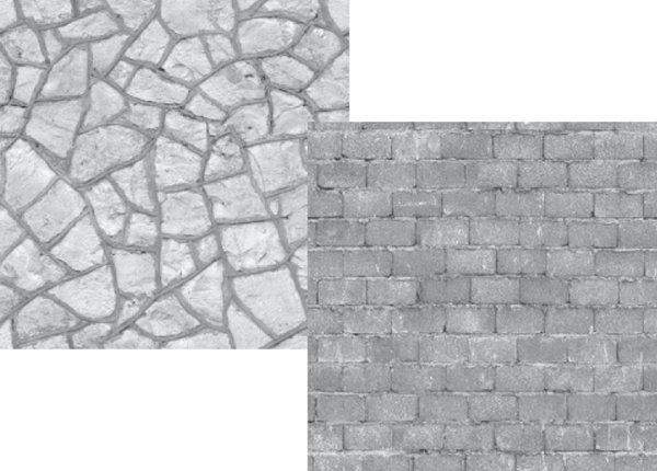
Figure 4.5 Seamlessly tiling stone and brick images obtained from textures.com
Download the images you want and prepare them for use as textures. Technically, you could use the images directly as they were downloaded, but those images aren’t ideal for use as textures. Although they’re certainly tileable (the important aspect of why you’re using these images), they aren’t the right size and they’re the wrong file format. Textures should be sized in powers of 2. For reasons of technical efficiency, graphics chips like to handle textures in sizes that are 2N: 4, 8, 16, 32, 64, 128, 256, 512, 1024, 2048 (the next number is 4096, but at that point the image is too big to use as a texture). In your image editor (Photoshop, GIMP, or whatever; refer to appendix B), scale the downloaded image to 256 x 256, and save it as a PNG.
Now drag the files from their location in the computer into the Project view in Unity. This will copy the files into your Unity project (see figure 4.6), at which point they’re imported as textures and can be used in the 3D scene. If dragging the file over would be awkward, you could instead right-click in Project and select Import New Asset to get a file picker.
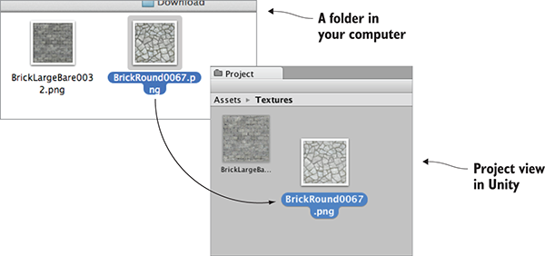
Figure 4.6 Drag images from outside Unity to import them into the Project view.
Now the images are imported into Unity as textures, ready to use. But how do we apply the textures to objects in the scene?
4.3.3 Applying the image
Technically, textures aren’t applied to geometry directly. Instead, textures can be part of materials, and materials are applied to geometry. As explained in the introduction, a material is a set of information defining the properties of a surface; that information can include a texture to display on that surface. This indirection is significant because the same texture can be used with multiple materials. That said, typically each texture goes with a different material, so for convenience Unity allows you to drop a texture onto an object and then it creates a new material automatically. If you drag a texture from Project view onto an object in the scene, Unity will create a new material and apply the new material to the object; figure 4.7 illustrates the maneuver. Try that now with the texture for the floor.
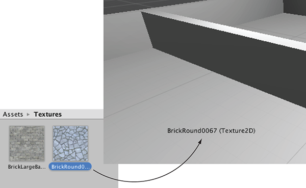
Figure 4.7 One way to apply textures is by dragging them from Project onto Scene objects.
Besides this convenience method of automatically creating materials, the “proper” way to create a material is through the Create submenu of the Assets menu; the new asset will appear in the Project view. Now select the material to show its properties in the Inspector (you’ll see something like figure 4.8) and drag a texture to the main texture slot; the setting is called Albedo (that’s a technical term for the base color) and the texture slot is the square to the side of the panel. Meanwhile, drag the material up from Project onto an object in the scene to apply the material to that object. Try these steps now with the texture for the wall: create a new material, drag the wall texture into this material, and drag the material onto a wall in the scene.
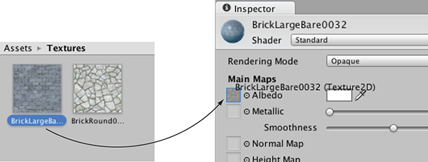
Figure 4.8 Select a material to see it in the Inspector, then drag textures to the material properties.
You should now see the stone and brick images appear on the surface of the floor and wall objects, but the images look rather stretched-out and blurry. What’s happening is the single image is being stretched out to cover the entire floor. What you want instead is for the image to repeat a few times over the floor surface. You can set this using the tiling property of the material; select the material in Project and then change the tiling number in the Inspector (with separate X and Y values for tiling in each direction). Make sure you’re setting the tiling of the main map and not the secondary map (this material supports a secondary texture map for advanced effects). The default tiling is 1 (that’s no tiling, with the image being stretched over the entire surface); change the number to something like 8 and see what happens in the scene. Change the numbers in both materials to tiling that looks good.
Great, now the scene has textures applied to the floor and walls! You can also apply textures to the sky of the scene; let’s look at that process.
4.4 Generating sky visuals using texture images
The brick and stone textures gave a much more natural look to the walls and floor. Yet the sky is currently blank and unnatural; we also want a realistic look for the sky. The most common approach to this task is a special kind of texturing using pictures of the sky.
4.4.1 What is a skybox?
By default, the camera’s background color is dark blue. Ordinarily, that color fills in any empty area of the view (for example, above the walls of this scene), but it’s possible to render pictures of the sky as background. This is where the concept of a skybox comes in.
Properly implementing a skybox can be tricky; figure 4.9 shows a diagram of how a skybox works. A number of rendering tricks are needed for the skybox to appear as a distant background. Fortunately, Unity already takes care of all that for you.
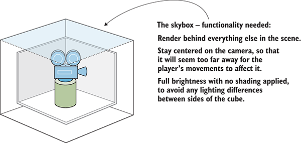
Figure 4.9 Diagram of a skybox
New scenes come with a very simple skybox already assigned to them. This is why the sky has a gradient from light to dark blue, rather than being a flat dark blue. If you open the lighting window (Window > Lighting > Settings), the first setting is Skybox Material and the slot for that setting says Default. This setting is in the Environment Lighting panel; this window has a number of settings panels related to the advanced lighting system in Unity, but for now, we only care about the first setting.
Just like the brick textures earlier, skybox images can be obtained from a variety of websites. Search for skybox textures; for example, I obtained several great skyboxes from https://93i.de/, including the TropicalSunnyDay set. Once this skybox is applied to the scene, you will see something like figure 4.10.
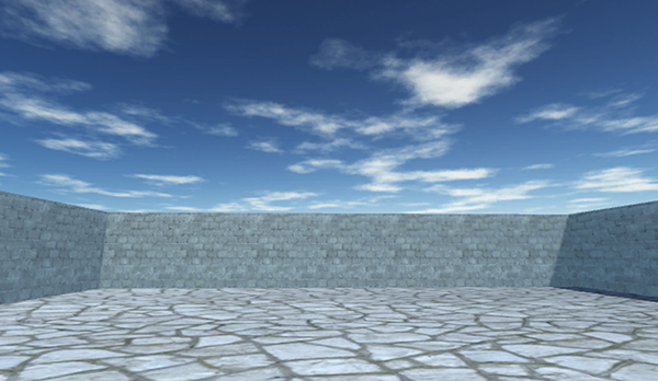
Figure 4.10 Scene with background pictures of the sky
As with other textures, skybox images are first assigned to a material, and that gets used in the scene. Let’s examine how to create a new skybox material.
4.4.2 Creating a new skybox material
First, create a new material (as usual, either right-click and Create, or choose Create from the Assets menu) and select it to see settings in the Inspector. Next, you need to change the shader used by this material. The top of the material settings has a Shader menu (see figure 4.11). In section 4.3, we pretty much ignored this menu because the default works fine for most standard texturing, but a skybox requires a special shader.
Every material has a shader that controls it (you could think of a material as an instance of a shader). New materials are set to the Standard shader by default. This shader displays the color of the material (including the texture) while applying basic dark and light across the surface.
For skyboxes, there’s a different shader. Click the menu in order to see the drop-down list (see figure 4.11) of all the available shaders. Move down to the Skybox section and choose 6 Sided in the submenu.
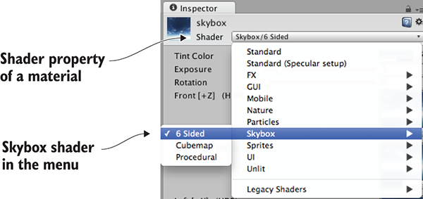
Figure 4.11 The drop-down menu of available shaders
With this shader active, the material now has six large texture slots (instead of only the small Albedo texture slot that the standard shader has). These six texture slots correspond to the six sides of a cube, so these images should match up at the edges in order to appear seamless. For example, figure 4.12 shows the images for the sunny skybox.
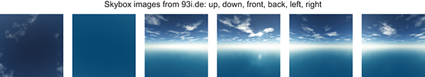
Figure 4.12 Six sides of a skybox—images for top, bottom, front, back, left, and right
Import the skybox images into Unity the same way you brought in the brick textures: drag the files into the Project view or right-click in Project and select Import New Asset. There’s one subtle import setting to change; click the imported texture to see its properties in the Inspector, and change the Wrap Mode setting (shown in figure 4.13) from Repeat to Clamp (don’t forget to click Apply when you’re done). Ordinarily, textures can be tiled repeatedly over a surface; for this to appear seamless, opposite edges of the image bleed together. But this blending of edges can create faint lines in the sky where images meet, so the Clamp setting (similar to the Clamp() function in chapter 2) will limit the boundaries of the texture and get rid of this blending.
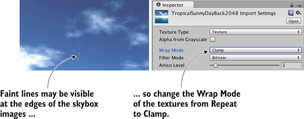
Figure 4.13 Correct faint edge lines by adjusting the Wrap mode.
Now you can drag these images to the texture slots of the skybox material. The names of the images correspond to the texture slot to assign them to (such as left or front). Once all six textures are linked up, you can use this new material as the skybox for the scene. Open the lighting window again and set this new material to the Skybox slot; either drag the material to that slot, or click the tiny circle icon to bring up a file picker.
Woo-hoo, you’ve learned how to create sky visuals for your scene! A skybox is an elegant way to create the illusion of a vast atmosphere surrounding the player. The next step in polishing the visuals in your level is to create more complex 3D models.
4.5 Working with custom 3D models
In the previous sections, we looked at applying textures to the large flat walls and floors of the level. But what about more detailed objects? What if you want, say, interesting furniture in the room? You can accomplish that by building 3D models in external 3D art apps. Recall the definition from the introduction to this chapter: 3D models are the mesh objects in the game (that is, the three-dimensional shapes). Well, you’re going to import a 3D mesh of a simple bench.
Applications widely used for modeling 3D objects include Autodesk’s Maya and 3ds Max. Those are both expensive commercial tools, so the sample for this chapter uses the open source app Blender. The sample download includes a .blend file that you can use; figure 4.14 depicts the bench model in Blender. If you’re interested in learning how to model your own objects, you’ll find an exercise in appendix C about modeling this bench in Blender.
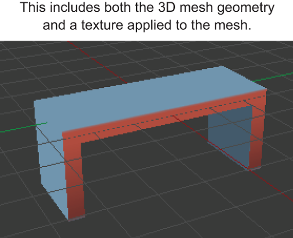
Figure 4.14 The bench model in Blender
Besides custom-made models created by yourself or an artist you’re working with, many 3D models are available for download from game art websites. One great resource for 3D models is Unity’s Asset Store: https://www.assetstore.unity3d.com.
4.5.1 Which file format to choose?
After you obtain a model made in an external art tool, you need to export the asset from that software. Just as with 2D images, a number of different file formats are available for you to use when exporting the 3D model, and these file types have various pros and cons. Table 4.3 lists the 3D file formats that Unity supports.
| File type | Pros and cons |
| FBX | Mesh and Animation; recommended option when available. |
| Collada (DAE) | Mesh and Animation; another good option when FBX isn’t available. |
| OBJ | Mesh only; this is a text format, so sometimes useful for streaming over the internet. |
| 3DS | Mesh only; a pretty old and primitive model format. |
| DXF | Mesh only; a pretty old and primitive model format. |
| Maya | Works via FBX; requires this application to be installed. |
| 3ds Max | Works via FBX; requires this application to be installed. |
| Blender | Works via FBX; requires this application to be installed. |
Choosing an option boils down to whether or not the file supports animation. Because Collada and FBX are the only two options that include animation data, those are the two options to choose. Whenever it’s available (not all 3D tools have it as an export option), FBX export tends to work best, but if you’re using a tool without FBX export, then Collada works well, too. In our case, Blender supports FBX export, so we’ll use that file format.
Note that the bottom of table 4.3 lists several 3D art applications. Unity allows you to directly drop those application’s files into your project, which seems handy at first, but that functionality has some caveats. For starters, Unity doesn’t load those application files directly; instead, it exports the model behind the scenes and loads that exported file. Because the model is being exported to FBX or Collada anyway, it’s preferable to do that step explicitly. Furthermore, this export requires you to have the relevant application installed. This requirement is a big hassle if you plan to share files among multiple computers (for example, a team of developers working together). I don’t recommend using 3D art application files directly in Unity.
4.5.2 Exporting and importing the model
All right, it’s time to export the model from Blender and then import it into Unity. First, open the bench in Blender and then choose File > Export > FBX. Once the file is saved, import it into Unity the same way that you import images. Drag the FBX file from the computer into Unity’s Project view or right-click in Project and choose Import New Asset. The 3D model will be copied into the Unity project and show up ready to be put in the scene.
There are a few default settings used to import the model that you want to change immediately. First, Unity defaults imported models to a very small scale (refer to figure 4.15, which shows what you see in the Inspector when you select the model); change the Scale Factor to 100 to partially counteract the .01 File Scale. You may also want to click the Generate Colliders check box, but that’s optional; without a collider you can walk through the bench. Then, switch to the Animation tab in the import settings and deselect Import Animation (you didn’t animate this model).
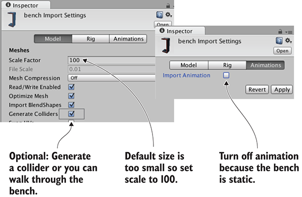
Figure 4.15 Adjust import settings for the 3D model.
That takes care of the imported mesh. Now for the texture; when Unity imported the FBX file, it also created a material for the bench. This material defaults to blank (just like any new material), so assign the bench texture (the image in figure 4.16) in the same way that you assigned bricks to the walls earlier: drag the texture image into Project to import it into Unity, and then drag the imported texture onto the texture slot of the bench material. The image looks somewhat odd, with different parts of the image appearing on different parts of the bench; the model’s texture coordinates were edited to define this mapping of image-to-mesh.
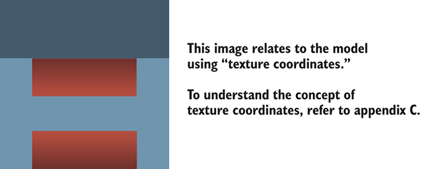
Figure 4.16 The 2D image for the bench texture
New materials are often too shiny, so you may want to reduce the Smoothness setting (smoother surfaces are more shiny) to 0. Finally, having adjusted everything as needed, you can put the bench in the scene. Drag the model up from the Project view and place it in one room of the level; as you drag the mouse, you should see it in the scene. Once you drop it in place, you should see something like figure 4.17. Congratulations; you’ve created a textured model for the level!
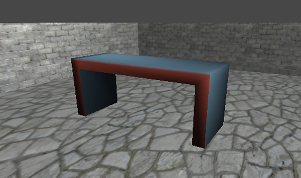
Figure 4.17 The imported bench in the level
4.6 Creating effects using particle systems
Besides 2D images and 3D models, the remaining type of visual content that game artists create are particle systems. The definition in this chapter’s introduction explained that particle systems are orderly mechanisms for creating and controlling large numbers of moving objects. Particle systems are useful for creating visual effects, like fire, smoke, or spraying water. The fire effect in figure 4.18 was created using a particle system.
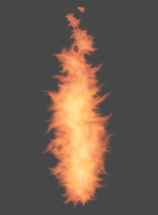
Figure 4.18 Fire effect created using a particle system
Whereas most other art assets are created in external tools and imported into the project, particle systems are created within Unity itself. Unity provides some flexible and powerful tools for creating particle effects.
To begin, create a new particle system and watch the default effect play. From the GameObject menu, choose Particle System, and you’ll see basic white puffballs spraying upward from the new object. Or rather, you’ll see particles spraying upward while you have the object selected; when you select a particle system, the particle playback panel is displayed in the corner of the screen and indicates how much time has elapsed (see figure 4.19).
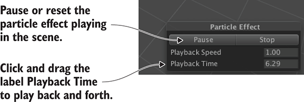
Figure 4.19 Playback panel for a particle system
The default effect looks pretty neat already, but let’s go through the extensive list of parameters you can use to customize the effect.
4.6.1 Adjusting parameters on the default effect
Figure 4.20 shows the entire list of settings for a particle system. We’re not going to go through every single setting in that list; instead, we’ll look at those relevant to making the fire effect. Once you understand how a few of the settings work, the rest should be fairly self-explanatory. Each setting’s labels is in fact a whole information panel. Initially, only the first information panel is expanded; the rest of the panels are collapsed. Click on the setting’s label to expand that information panel.
Adjust parameters of the particle system as indicated in figure 4.20 and it’ll look more like a jet of flame.
4.6.2 Applying a new texture for fire
Now the particle system looks more like a jet of flame, but the effect still needs the particles to look like flame, not white blobs. That requires importing a new image into Unity. Figure 4.21 depicts the image I painted; I made an orange dot and used the Smudge tool to draw out the tendrils of the flame (and then I drew the same thing in yellow). Whether you use this image from the sample project, draw your own, or download a similar one, you need to import the image file into Unity. As explained previously, drag image files into the Project view, or choose Assets > Import New Asset.
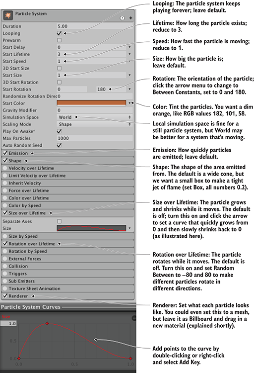
Figure 4.20 The Inspector displays settings for a particle system (pointing out settings for the fire effect).

Figure 4.21 The image used for fire particles
Just like with 3D models, textures aren’t applied to particle systems directly; you add the texture to a material and apply that material to the particle system. Create a new material and then select it to see its properties in the Inspector. Drag the fire image from Project up to the texture slot. That links the fire texture to the fire material, so now you want to apply the material to the particle system. Figure 4.22 shows how to do this; select the particle system, expand Renderer at the bottom of the settings, and drag the material onto the Material slot.
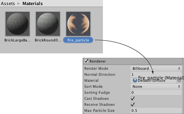
Figure 4.22 Assign a material to the particle system.
As you did for the skybox material, you need to change the shader for a particle material. Click the Shader menu near the top of the material settings to see the list of available shaders. Instead of the standard default, a material for particles needs one of the shaders under the Particles submenu. As shown in figure 4.23, in this case, we want Additive (Soft). This will make the particles appear to be hazy and brighten the scene, just like a fire.
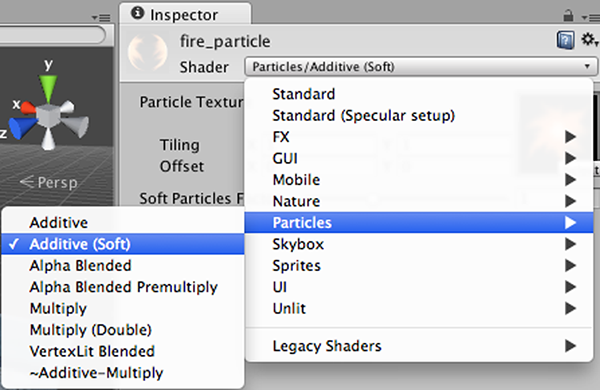
Figure 4.23 Setting the shader for the fire particle material
With the fire material assigned to the fire particle effect, it’ll now look like the effect shown in figure 4.18. This looks like a pretty convincing jet of flame, but the effect doesn’t only work when sitting still; next, let’s attach it to an object that moves around.
4.6.3 Attaching particle effects to 3D objects
Create a sphere (remember, GameObject > 3D Object > Sphere). Create a new script called BackAndForth and attach it to the new sphere.
Listing 4.1 Moving an object back and forth along a straight path
using UnityEngine;
using System.Collections;

public class BackAndForth : MonoBehaviour {
    public float speed = 3.0f;
    public float maxZ = 16.0f;
    public float minZ = -16.0f;
    private int _direction = 1;
    void Update() {
        transform.Translate(0, 0, _direction * speed * Time.deltaTime);

        bool bounced = false;
        if (transform.position.z > maxZ || transform.position.z < minZ) {
            _direction = -_direction;
            bounced = true;
        }
        if (bounced) {
            transform.Translate(0, 0, _direction * speed * Time.deltaTime);
        }
    }
}
Run this script and the sphere glides back and forth in the central corridor of the level. Now you can make the particle system a child of the sphere and the fire will move with the sphere. Just like with the walls of the level, in the Hierarchy view, drag the particle object onto the sphere object.
Now the particle system moves along with the sphere. However, the fire isn’t deflecting from the movement, which looks unnatural. That’s because, by default, particles move correctly only in the local space of the particle system. To complete the flaming sphere, find Simulation Space in the particle system settings (it’s in the top panel of figure 4.20) and switch from Local to World.
I’m sure that, at this point, you’re itching to apply your own ideas and add more content to this sample game. You should do that—you could create more art assets, or even test your skills by bringing in the shooting mechanics developed in chapter 3. In the next chapter, we’ll switch gears to a different game genre and start over with a new game. Even though future chapters will switch to different game genres, everything from these first four chapters will still apply and will be useful.
Summary
- Art asset is the term for all individual graphics.
- Whiteboxing is a useful first step for level designers to block out spaces.
- Textures are 2D images displayed on the surface of 3D models.
- 3D models are created outside Unity and imported as FBX files.
- Particle systems are used to create many visual effects (fire, smoke, water, and so on).