Table of Contents for
Unity in Action, Second Edition
 Unity in Action, Second Edition
Published by
Manning Publications, 2018
Unity in Action, Second Edition
Published by
Manning Publications, 2018
- Cover
- Unity in Action
- Praise for the First Edition
- Titlepage
- Copyright
- foreword
- preface
- acknowledgments
- about this book
- about the author
- about the cover illustration
- Part 1: First steps
- Chapter 1: Getting to know Unity
- Chapter 2: Building a demo that puts you in 3D space
- Chapter 3: Adding enemies and projectiles to the 3D game
- Chapter 4: Developing graphics for your game
- Part 2: Getting comfortable
- Chapter 5: Building a Memory game using Unity’s 2D functionality
- Chapter 6: Creating a basic 2D platformer
- Chapter 7: Putting a GUI onto a game
- Chapter 8: Creating a third-person 3D game: player movement and animation
- Chapter 9: Adding interactive devices and items within the game
- Part 3: Strong finish
- Chapter 10: Connecting your game to the internet
- Chapter 11: Playing audio: sound effects and music
- Chapter 12: Putting the parts together into a complete game
- Chapter 13: Deploying your game to players’ devices
- afterword
- Appendix A: Scene navigation and keyboard shortcuts
- Appendix B: External tools used alongside Unity
- Appendix C: Modeling a bench in Blender
- Appendix D: Online learning resources
- Index
appendix C
Modeling a bench in Blender
In chapters 2 and 4, we looked at creating levels with large flat walls and floors. But what about more detailed objects? What if you want, say, interesting furniture in the room? You can accomplish that by building 3D models in external 3D art apps. Recall the definition from the introduction to chapter 4: 3D models are the mesh objects in the game (that is, the 3D shapes). In this appendix, I’ll show you how to create a mesh object of a simple bench (figure C.1).
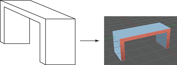
Figure C.1 Diagram of the simple bench you’re going to model.
Although appendix B lists a number of 3D art tools, we’ll use Blender for this exercise because it’s open source and thus accessible to all readers. You’ll create a mesh object in Blender and export that to an art asset that works with Unity.
Building the mesh geometry
Launch Blender; the initial default screen looks like figure C.2, with a cube in the middle of the scene. Use the middle mouse button to manipulate the camera view: click and drag to tumble, Shift with click-drag to pan, and Control with click-drag to zoom.
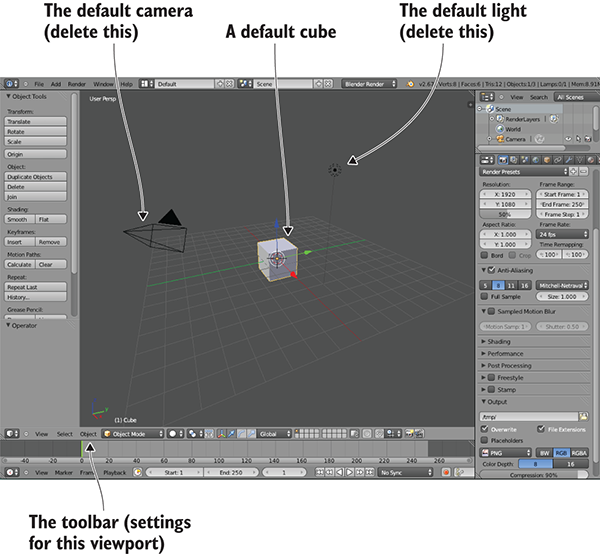
Figure C.2 The initial default screen in Blender
Blender starts out in Object mode, which, as the name implies, is when you manipulate entire objects, moving them around the scene. To edit a single object in detail, you must switch to Edit mode; figure C.3 shows the menu you use (Edit appears in this menu only when an object is selected, and Blender starts out with the object selected). Similarly, when you first switch to Edit mode, Blender is set to Vertex Selection mode, but there are buttons (refer to figure C.4) that let you switch between Vertex, Edge, and Face Selection modes. The various selection modes allow you to select different mesh elements.
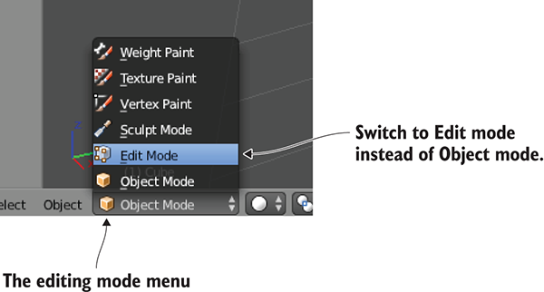
Figure C.3 Menu for switching from Object to Edit mode
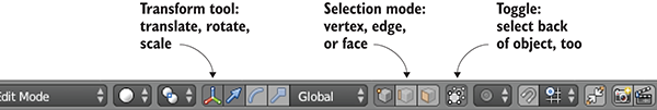
Figure C.4 Controls along the bottom of the viewport
These are the basic controls for using Blender, so now we’ll see some functions for editing the model. To start, scale the cube into a long, thin plank. Select every vertex of the model (be sure to also select vertices on the side of the object facing away) and then switch to the Scale tool. Click-drag the blue arrow for the Z-axis to scale down vertically, and then click-drag the green arrow for Y to scale out sideways (see figure C.5).
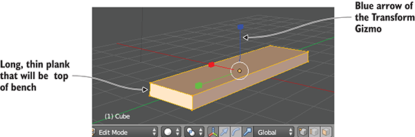
Figure C.5 Mesh scaled into a long, thin plank
Switch to Face Selection mode (use the button indicated in figure C.4) and select both small ends of the plank. Now click on the Mesh menu at the bottom of the viewport and select Extrude Individual (see figure C.6). As you move the mouse you’ll see additional sections added to the ends of the plank; move them out slightly and then left-click to confirm. This additional section is only the width of the bench legs, giving you a little additional geometry to work with.
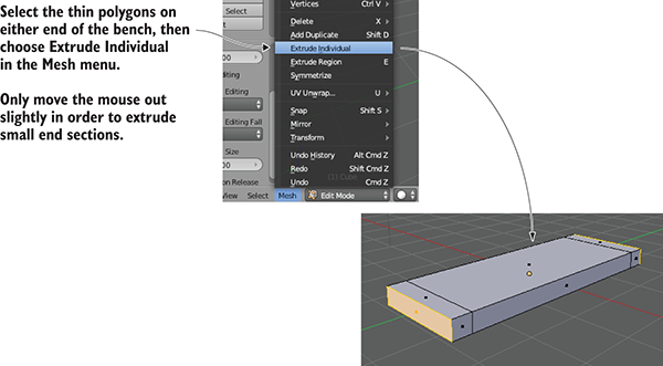
Figure C.6 In the Mesh menu, use Extrude Individual to pull out extra sections.
Now look at the bottom of the plank and select the two thin faces on each end. Use the Extrude Individual command again to pull down legs for the bench (refer to figure C.7).
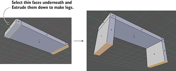
Figure C.7 Select the thin faces underneath the bench and pull down legs.
The shape is complete! But before you export the model over to Unity, you want to take care of texturing the model.
Texture-mapping the model
3D models can have 2D images (referred to as textures) displayed on their surface. How exactly the 2D images relate to the 3D surface is straightforward for a large flat surface like a wall: simply stretch the image across the flat surface. But what about an oddly shaped surface, like the sides of the bench? This is where it becomes important to understand the concept of texture coordinates.
Texture coordinates define how parts of the texture relate to parts of the mesh. These coordinates assign mesh elements to areas of the texture. Think about it like wrapping paper (see figure C.8); the 3D model is the box being wrapped, the texture is the wrapping paper, and the texture coordinates represent where on the wrapping paper each side of the box will go. The texture coordinates define points and shapes on the 2D image; those shapes correlate to polygons on the mesh, and that part of the image appears on that part of the mesh.
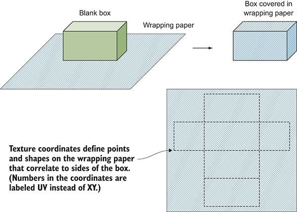
Figure C.8 Wrapping paper makes a good analogy for how texture coordinates work.
The technical term for correlating part of one thing to part of another is mapping—hence the term texture mapping for the process of creating texture coordinates. Coming from the wrapping paper analogy, another name for the process is unwrapping. And then there are terms created by mashing up the other terminology, like UV unwrapping; there are a lot of essentially synonymous terms surrounding texture mapping, so try not to get confused.
Traditionally, the process of texture mapping has been wickedly complicated, but fortunately, Blender provides tools to make the process fairly simple. First you define seams on the model; if you think further about wrapping around a box (or better yet, think about the other direction, unfolding a box) you’ll realize that not every part of a 3D shape can remain seamless when unfolded into two dimensions. There will have to be seams in the 3D form where the sides come apart. Blender enables you to select edges and declare them as seams.
Switch to Edge Selection mode (see the buttons in figure C.4) and select the edges along the outside of the bottom of the bench. Now select Mesh > Edges > Mark Seam (see figure C.9). This tells Blender to separate the bottom of the bench for the purposes of texture mapping. Do the same thing for the sides of the bench, but don’t separate the sides entirely. Instead, only seam edges running up the legs of the bench; this way, the sides will remain connected to the bench while spreading out like wings.
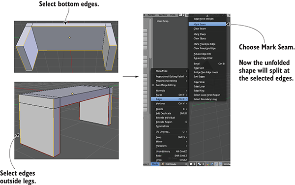
Figure C.9 Seam edges along the bottom of the bench and along the legs
Once all the seams are marked, run the Texture Unwrap command. First, select the entire mesh (don’t forget the side of the object facing away). Next, choose Mesh > UV Unwrap > Unwrap to create the texture coordinates. But you can’t see the texture coordinates in this view; Blender defaults to a 3D view of the scene. To see the texture coordinates, you must switch from 3D View to UV Editor, using the Viewports menu located on the far left of the toolbar (not the word View but the little icon; see figure C.10).
Now you can see the texture coordinates. You can see the polygons of the bench laid out flat, separated, and unfolded according to the seams you marked. To paint a texture, you have to see these UV coordinates in your image-editing program. Referring again to figure C.10, under the UVs menu, choose Export UV Layout; save the image as bench.png (this name will also be used later when importing into Unity).
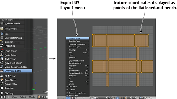
Figure C.10 Switch from 3D View to UV Editor, where the texture coordinates are displayed.
Open this image in your image editor and paint colors for the various parts of your texture. Painting different colors for different UVs will put different colors on those faces. For example, figure C.11 shows darker blue where the bottom of the bench was unfolded on the top of the UV layout, and red was painted on the sides of the bench. Now the image can be brought back into Blender to texture the model; select Image > Open Image.
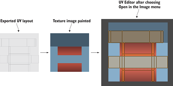
Figure C.11 Paint colors over the exported UVs and then bring the texture into Blender.
At this point, you can return to the 3D view (using the same menu you used to switch to UV Editor). You still can’t see the texture on the model, but that only requires a couple more steps. You need to delete the default light and then turn on textures in the viewport (see figure C.12).
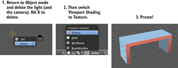
Figure C.12 Delete the default light and view the texture on the model.
To delete the light, first switch back to Object mode in order to select it (using the same menu you used to switch to Edit mode). Press X to delete a selected object; delete the camera while you’re at it. Finally, go to the Viewport Shading menu to switch to Texture. Now you can see the finished bench, with texture applied!
Save the model now. Blender will save the file with the .blend extension, using the native file format for Blender. Work in the native file format so that all the features of Blender will be preserved correctly, but later you’ll have to export the model to a different file format to import it into Unity. Note that the texture image isn’t saved in the model file; what’s saved is a reference to the image, but you still need the image file that’s being referenced.