
One embedded system hardware device that has not been covered yet is the keypad. Applications for it range from specialized calculators, combination locks, or simple data input keypads. Normally these have their buttons arranged in rows and columns so that they can be scanned by the host computer, reducing the number of I/O ports necessary. You’ll do the same in this chapter but using the DIP form of the PCF8574 I/O chip to avoid using up precious GPIO ports.
You have seen this chip before as part of the PCB adapter to the LCD in Chapter 4. The project presented here will make use of the dual inline package (DIP) form of the I2C I/O extender and operate it from the Pi’s 3.3V supply instead. As a 16-pin chip, it is easy to wire up on a breadboard. Using the I2C bus permits the possibility of a keypad at some distance from the Pi using only power and two I2C lines.
Breadboard Setup
The best place to start is the wiring of the pair of PCF8574P chips on the breadboard, as shown in Figure 13-1 (the second chip is optional). Do this with the Pi powered off and leave out the keypad for now.
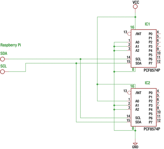
Figure 13-1. The PCF8574P wiring to the Raspberry Pi’s I2C bus (VCC=+3.3 volts)
Caution
Use the +3.3V Raspberry Pi power for this project. Nothing in this experiment uses the +5V supply.
Figure 13-1 shows two PCF8574P chips wired up to the I2C bus. The second chip is optional but recommended. This second chip will be used to drive an LED indicator. Note that IC2’s A0 is connected to the +3.3V supply so that its I2C address will be 0x21. IC1 will have address 0x20 because its inputs are all tied to ground.
With the wiring done and the Pi booted up, you should now be able to perform some simple tests on it. Let’s check to see whether the two chips are detected on the bus.
$ i2cdetect -y 10 1 2 3 4 5 6 7 8 9 a b c d e f00: -- -- -- -- -- -- -- -- -- -- -- -- --10: -- -- -- -- -- -- -- -- -- -- -- -- -- -- -- --20: 20 21 -- -- -- -- -- -- -- -- -- -- -- -- -- --30: -- -- -- -- -- -- -- -- -- -- -- -- -- -- -- --40: -- -- -- -- -- -- -- -- -- -- -- -- -- -- -- --50: -- -- -- -- -- -- -- -- -- -- -- -- -- -- -- --60: -- -- -- -- -- -- -- -- -- -- -- -- -- -- -- --70: -- -- -- -- -- -- -- --
If all went well, the i2cdetect command should find addresses 20 and 21 (hexadecimal) as shown. The 1 on the i2cdetect command line specifies I2C bus 1.
If you see zero or one addresses, check that you’ve wired the A0, A1, and A2 pins of IC1 and IC2 correctly. If you wired them both in the same way, both chips will try to respond to the same address. Alternatively, this could result in neither being seen. These addresses must be unique on the bus. You can use different addresses than the ones I chose, but the software presented later will expect addresses 0x20 and 0x21.
Output Tests
The supplied I2C utilities allow you to try these chips without writing any code. Let’s write the value 0xFF to IC1 to set all outputs high.
$ i2cset -y -r 1 0x20 0xFFValue 0xff written, readback matched
This command example skips interactive mode (-y) and reads back from the chip (-r) as verification. The fact that the command responded with “readback matched” gives you confidence that this write was successful. Otherwise, you can drop the -r option.
$ i2cset -y 1 0x20 0xFFSome of you might be grabbing some LEDs now to hook one up. Hold off on that since there are some specifics about this chip that must be taken into account (hint: you must sink the LED current rather than source it). This will be discussed later in this chapter. But do go and get your DMM so that you can take some voltage readings.
With your DMM, you can check the outputs of IC1. Outputs P0 through P7 should all measure high (+3.3 volts). Now let’s set P0 to 0, while leaving all other outputs high.
$ i2cset -y 1 0x20 0xFENow measure P0 on IC1 (pin 4). Does it read low? All other pins P1 through P7 should remain high. If so, congratulations! Now repeat the experiment with address 0x21 for IC2. You should be able to repeat the results.
Note
All PCF8574 outputs are initialized high at power on reset.
Input Tests
The datasheet for the PCF8574 describes this chip as a quasi-bidirectional I/O port. What on Earth does that mean?
One of the great things about this chip is that there is virtually no configuration involved. If you want to output a bit pattern, you simply write to that I/O port like you did with the i2cset command (or using a system call in C/C++). Reading an input value, however, requires one little setup step. You must first write 1 bits to each position that you want to read from and then perform the read. The write operation needs to be performed only once—you can consider that the configuration step. That’s why I said “virtually” no configuration.
Once a bit position has a 1 bit written to it, you can read from it. Let’s set all IC1 outputs to 1s again so that all eight bits are inputs.
$ i2cset -y 1 0x20 0xFFIf you now took the time to measure P0 through P7 with your DMM on IC1, they would all show as high again. However, in this state, the designers of the chip have effectively just enabled a resistor internally to the supply side. This causes the ports to measure high by your DMM. However, since these are all basically linked to the supply by internal resistance, you can pull these down to force a 0 (low) on those pins without causing damage.
To test this, pick a pin, say P3, which is pin 7 of IC1. Attach a Dupont wire from pin 8 (IC1’s ground) to pin 7. Then let’s read the port.
$ i2cget -y 1 0x200xf7
The hex value of F7 indicates that bit 3 has been read low while all other bits have remained high. If you now remove that Dupont wire, you should read a high in bit 3 again.
$ i2cget -y 1 0x200xff
Confirmed. In this case, without the grounding of P3, the output driver internal to the chip is pulling it high once again. Hence, when you read it back, it has returned to a 1 bit. Grounding P3, on the other hand, forced it to read low even though there was a slight tug to the positive side internally. There is a small tug of war going on in there, but this one is designed to be safe.
High-Side Driver
Let’s expand on this high-side driver concept a bit more. The TI datasheet shows that when the output port is driven high, a 100μA constant current source is activated. If you short that output to ground, as you did when supplying a 0 bit to the input port, you are actually causing 100μA to flow from the supply to ground. This is not a large amount of current, so it remains safe to do. Applying Ohm’s law, you can calculate the effective resistance, which amounts to the following:
So, while the internal resistance is not actually a resistor, it behaves as if there was a 33kΩ resistor tied to the supply side.
People working with the Raspberry Pi or Arduino devices will often wire up an LED, which is turned on when the output port is set high. This is known as sourcing the current through the LED since the current comes from the port (indirectly the supply rail). This is perfectly acceptable when the output port supports this. But the PCF8574 will not source more than 100μA of current. Most LEDs require about 2mA or more before it will emit any light.
While 100μA is not a lot of drive current, it is perfectly adequate for driving high inputs of other CMOS inputs. But driving an LED with the PCF8574, however, requires that you to sink the current instead.
Low-Side Driver
The low-side output driver of the PCF8574 can handle up to 25mA maximum (TI). When you write a 0 bit to the output, that output transistor will conduct up to 25mA of current from that pin (Px) to ground. Because the current is going to ground, this is known as sinking the current.
It is at this point where you interrupt this program to warn about a tug of war that can be fatal. Say you have an external circuit sending its output to your PCF8574 input. If your port has been set to a 0 bit, perhaps because of a software bug, then a high amount of current will flow from that external circuit into the PCF8574’s sinking transistor, when the external circuit’s level is high. This is effectively a short circuit, which left unremedied can mean failure. This is why the PCF8574 powers on in the high state, which is always safe.
If this tug of war possibility exists in your design, you can protect the external circuit and the PCF8574 by wiring them through a 1kΩ resistor. This limits the short-circuit current to a safe level of 1mA and does not interfere with the transmission of the signal.
Driving an LED
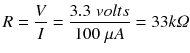
Figure 13-2 shows the two different ways that an LED can be driven from an output port. The left side shows an LED being sourced with current from Px, using R1 as a current-limiting resistor. When the output port is set to a 1 bit (active high), the LED is expected to light. This will not work for the PCF8574, since the high-side driver will not supply more than 100μA.
Figure 13-2. PCF8574 sourcing (incorrect) and sinking (correct) of current
The right side of Figure 13-2 shows the correct way to drive an LED from the PCF8574. Using this circuit, the current is sourced by the power supply, and the current is sinked by the output port Px. In this case, the LED is lit when the output is written as a 0 bit (active low). Up to a maximum of 25mA can be driven this way by the PCF8574.
The Keypad
Figure 13-3 illustrates the top side of the keypad I am going to use for this experiment. I chose this format because it is arranged as a 4×4 matrix of buttons and is cheap on eBay ($1.25). If you look carefully at the copper traces of Figure 13-3 and the bottom side of Figure 13-4, you can see how the buttons are wired in four rows and four columns. This will allow you to sense the keypad with four outputs and four inputs.
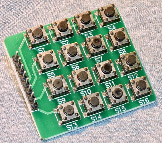
Figure 13-3. Keypad with 16 buttons. Note the copper traces on the top side going to the edge connector.
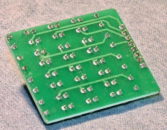
Figure 13-4. Bottom view of the keypad. Note the copper traces going to the edge connector and where pin 1 is, with the square pad.
In rummaging through my junk parts, I came across some old calculator keypads that I have saved since the early 1980s (Figure 13-5). These were purchased by mail order catalog and are still like new. These keypads occasionally show up on eBay, though usually at a higher price ($7). But before you purchase these for a project, realize that these are not always organized in a matrix. My Figure 13-5 keypads have 12 connections and a ground. In other words, all 12 keys are arranged in one electrical row.
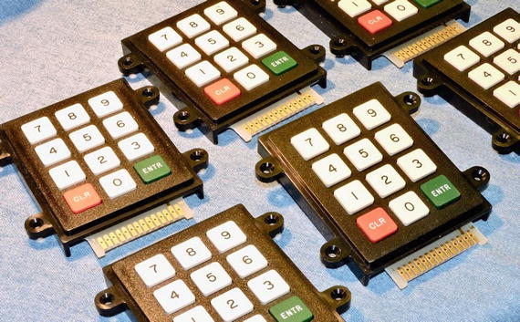
Figure 13-5. Some oldies but goodies from the 1980s
Looking at the bottom side of the hex keypad in Figure 13-4, make note of where pin 1 is. It is the square pad shown at the bottom right of the figure. This pin appears on the top side of the board nearest S13 on the silk screening (Figure 13-3). If you are using the same keypad and have the pin 1 located, you should be able to reproduce the same results developed in this chapter. You can of course use a different keypad, but you’ll have to make the appropriate adjustments.
From a breadboard perspective, the header strip on the keypad is inconvenient. To bring the keypad interface onto the breadboard, you may want to use some female-to-male Dupont wires. Ideally a pair of four-conductor cables would work best. I had to use four two-conductor wires instead. Arrange these cables to bring the eight connections from the keypad to the breadboard for ease of wiring.
Figure 13-6 illustrates the connections inside the keypad, as well as their terminal connections T1 through T8. These are wired on the breadboard to IC1’s Px, as shown in brackets. With no keys pressed, you can see that there are no connections between any of the T1 through T4 rows to any of the columns T5 through T8. But when button SW7 is pressed, a connection is made between row T3 to column T7.
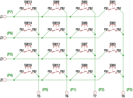
Figure 13-6. Keypad connections diagram
After making the connections between the keypad and IC1, as shown in Figure 13-6, you can manually run some experiments using the I2C tool commands. First, let’s configure the left four bits as 0 bits and the right four bits as 1 bits so you can read from them.
$ i2cset -y 1 0x20 0x0FNow using the bash shell, let’s enter a loop that will slowly read IC1 for any changes.
$ while true; do i2cget -y 1 0x20; sleep 1; doneThis loop will do an i2cget read in a loop, with a one-second delay between each read. Use Control-C to stop it later. With the command running, you will initially see this:
0x0fThis is to be expected since you wrote that pattern out to the port. While that continues to run, successively press S1 through S4. Do you see this?
$ while true; do i2cget -y 1 0x20; sleep 1; done0x0f0x0e0x0f0x0d0x0f0x0b0x0f0x070x0f^C
Once again, the first 0x0f is the port-configured value. However, when I pressed button S1 (and waited), 0x0e was returned. After releasing S1, the next reading was 0x0f again. Pressing S2 returned 0x0d, S3 returned 0x0b, and S4 returned 0x07. This demonstrates that you were able to read rows T1 through T4 as bits 3 through 0 of IC1’s port.
Now repeat the experiment with buttons S5 through S8, S9 through S12, and S13 through S16. You should get the same results. These all return button presses because you have all rows T1 through T4 set low. Let’s now make the reading more specific. Set row T3 to low, while T1, T2, and T4 are high with the hex value 0xDF (the bits used are 11011111, specifying only bit 5 as zero).
$ i2cset -y 1 0x20 0xDFWith only bit 5 set low, only button presses in column T7 will ever read a low (buttons S5 through S8). By scanning T1 through T4, you can detect columns that have button presses.
Before presenting C++ code to scan the keypad, let’s do one more manual experiment. With the output still set to 0xDF, what happens if you simultaneously press S5, S6, S7, and S8?
$ while true; do i2cget -y 1 0x20; sleep 1; done0xdf0xd50xdd0xdf0xd80xd00xdf^C
It was a bit of a struggle for me to get all the buttons simultaneously pushed down in that row, but eventually I succeeded (the value reported was 0xd0). This illustrates the fact that the program scanning the keyboard must be prepared to filter these events out or return them as a keycode of some sort. This is similar to the kind of thing that your PC keyboard must do when it sees the Microsoft-made-famous Control-Alt-Delete.
Keypad Program
In your source directory, change to the keypad subdirectory and type make, if you haven’t already compiled the code.
$ cd keypad$ make
With the executable keypad built, run it and press some buttons. In the session shown, I pressed S1, S6, S11, and S16 in a diagonal.
$ ./keypadkeypress: EE (S1)release: EE (S1)keypress: DD (S6)release: DD (S6)keypress: BB (S11)release: BB (S11)keypress: 77 (S16)release: 77 (S16)
The two-digit hexadecimal number shown is effectively the “scan code” that you saw previously using the i2cget utility. Recall that the left four bits select a row, and the right four represent the column selected. The program then looks up the scan code to translate that into a “key name,” like S1.
The main Program
Listing 13-1 shows the source code for the main program. Lines 113 to 119 open the I2C bus driver, saving the file descriptor i2c_fd. This file descriptor provides you with a handle to the driver.
Listing 13-1. The main Program of keypad.cpp
108 int109 main(int argc,char **argv) {110 uint8_t keypad, row, col;111112 // Open the I2C bus113 i2c_fd = open(i2c_device,O_RDWR);114 if ( i2c_fd == -1 ) {115 fprintf(stderr,"%s: opening %s\n",116 strerror(errno),117 i2c_device);118 exit(1);119 }120121 for (;;) {122 // Scan each keypad row:123 for ( row=0x10; row != 0; row <<= 1 ) {124 // Drive the row select125 i2c_write(i2c_keypad_addr,∼row);126127 // Read the column inputs128 keypad = i2c_read(i2c_keypad_addr);129 col = keypad & 0x0F;130131 if ( col != 0x0F ) {132 // Keypress event133 printf("keypress: %02X (%s)\n",134 keypad,135 key_lookup(keypad));136137 while ( (i2c_read(i2c_keypad_addr) & 0x0F) == col )138 usleep(50000);139140 printf("release: %02X (%s)\n\n",141 keypad,142 key_lookup(keypad));143 }144 usleep(50000);145 }146 }147148 return 0;149 }
The remainder of the main program starting with the for loop in line 121 is the keypad-reading loop. This loop will execute until your Control-C to interrupt the program.
Inside the outer loop, there is an inner for loop starting in line 123. According to the loop construction, the value row starts with 0x10, continues as long as the value row is nonzero, and is shifted left one bit at the end of each loop. For the nonveteran C/C++ programmers, let’s summarize the values involved in Table 13-1.
Table 13-1. The for Loop Iteration Values for the Variable row
Iteration | Row (Hex) | Row (Bits) | ∼Row (Hex) | ∼Row (Bits) | Description |
|---|---|---|---|---|---|
0 | 0x10 | 0b00010000 | 0xEF | 0b11101111 | Row 0 selected |
1 | 0x20 | 0b00100000 | 0xDF | 0b11011111 | Row 1 selected |
2 | 0x40 | 0b01000000 | 0xBF | 0b10111111 | Row 2 selected |
3 | 0x80 | 0b10000000 | 0x7F | 0b01111111 | Row 3 selected |
4 | 0x00 | 0b00000000 | 0xFF | 0b11111111 | No rows selected |
Recall that the column bits are input ports, requiring 1 bits to be written to the lower four bits. Further, to select a row of buttons, you need to set the bit low for the row so that a button can be sensed. So, the loop starts the first iteration with row set to 0x10. When inverted, this sets bit 4 low and the remaining bits high (hex value 0xEF). This is the value you write to the PCF8574 port in line 125 (note that ∼row is the value of row with the bits inverted).
At the end of the loop, you need to scan the next row. Using the noninverted row value permits you to test after the shift left operation when the last bit was shifted out, which will result in zero. This provides a convenient for loop variable, even though it is the inverted value that you need for the I2C device.
After priming the I2C port with a write in line 125, you then read back from the same port in line 128. If no key has been pressed, you will simply read back the same value that was just written. But when a key is pressed, one of the buttons connected to the row will cause a zero bit to appear in the lower four bits of the value read. You test for this condition in lines 129 and 131.
When a keypress has occurred, you report this using printf in line 133 (you’ll examine the function key_lookup later). Lines 137 and 138 wait for the key press to be released. Any change in the pressed key state causes the while loop to exit. The usleep releases the CPU briefly to allow other processes to run. Finally, after the key has been released, printf in line 140 announces this to stdout.
The bottom of the scan loop also calls usleep so that the CPU utilization isn’t squandered (line 144).
The key_lookup Function
Depending upon your application, using the scan codes may be sufficient. In many cases, however, some kind of translation between the scan code and the key symbol is required. Listing 13-2 shows the key_lookup function that was used in the keypad.cpp program.
Listing 13-2. The key_lookup Function
024 static std::unordered_map<uint8_t,std::string> keymap({025 { 0xEE, "S1" }, { 0xED, "S2" }, { 0xEB, "S3" },026 { 0xE7, "S4" }, { 0xDE, "S5" }, { 0xDD, "S6" },027 { 0xDB, "S7" }, { 0xD7, "S8" }, { 0xBE, "S9" },028 { 0xBD, "S10" }, { 0xBB, "S11" }, { 0xB7, "S12" },029 { 0x7E, "S13" }, { 0x7D, "S14" }, { 0x7B, "S15" },030 { 0x77, "S16" }031 });...095 const char *096 key_lookup(uint8_t scancode) {097098 auto it = keymap.find(scancode);099 if ( it != keymap.end() )100 return it->second.c_str();101 return "???"; // Multiple keys pressed102 }
Lines 024 to 031 at the top of the source module declare and initialize an unordered map named keymap. This map is designed to accept a scan code of type uint8_t and return an associated string name for it. So, if 0xED is queried, the value "S2" is returned. Note that keymap is created and initialized before main begins to execute.
The function key_lookup accepts the scan code as its input argument (line 096). Line 098 performs the keymap lookup based on it. If the value is known, the iterator value it will have a value that differs from keymap.end() in line 099. In this case, you returned the key’s string value. Note here that it->second is C++ type std::string. To return a C-styled string, you convert that by invoking the method c_str(). This pointer value remains valid as long as the values in keymap are left unmodified.
Line 101 is in place for scan codes that you don’t have defined in keymap. You might think that you have them all covered, but if you press more than one key simultaneously, other scan codes are possible. For example, the scan code 0xE6 is returned if you simultaneously press S1 and S4.
The i2c_write Function
Listing 13-3 shows the i2c_write function. This function is used to write one byte of information to the PCF8574 peripheral chip.
Listing 13-3. The i2c_write Function
037 void038 i2c_write(int addr,uint8_t byte) {039 struct i2c_rdwr_ioctl_data msgset;040 struct i2c_msg iomsgs[1];041 int rc;042043 iomsgs[0].addr = unsigned(addr);// Address044 iomsgs[0].flags = 0; // Write045 iomsgs[0].buf = &byte; // Buffer046 iomsgs[0].len = 1; // 1 byte047048 msgset.msgs = iomsgs; // The message049 msgset.nmsgs = 1; // 1 message050051 rc = ioctl(i2c_fd,I2C_RDWR,&msgset);052 if ( rc == -1 ) {053 fprintf(stderr,054 "%s: writing to I2C address 0x%02X\n",055 strerror(errno),056 i2c_keypad_addr);057 exit(1);058 }059 }
The Linux I2C driver requires you to use two structures.
struct i2c_rdwr_ioctl_data
struct i2c_msg
The first structure is a header record that describes aspects of the transfer that apply to the entire transaction. You see this in lines 048 and 049, where you save the pointer to the first transaction (line 048) and then the number of consecutive transactions to be performed (line 049).
The i2c_msg structure defines the aspects of each I/O transfer to be performed. In the listing, line 043 first defines the I2C address involved. Line 044 defines this operation as a write operation (this is because of the lack of the I2C_M_RD flag, which will be seen in the i2c_read function later). Line 045 defines where the buffer is located (the variable byte). Finally, the transfer will involve one byte (line 046).
With the structures fully populated, the communication with the driver occurs through the ioctl(2) system call in line 051. The following are the arguments involved in the call:
The driver’s file descriptor (i2c_fd)
The ioctl(2) command value (I2C_RDWR macro)
Pointer to the associated data for this operation (address of msgset)
The system call returns -1 if the operation failed for any reason, leaving the error code in the thread-safe value of errno. Line 052 checks the status returned and reports the error in lines 053 to 056 if it fails and then exits the program in line 057. If the operation succeeds, you simply return from the function as “mission accomplished.”
The i2c_read Function
A companion to the i2c_write function is the i2c_read function. In this application program, its mission is to simply read one byte of data (from the PCF8574 peripheral). Listing 13-4 shows the code for this function.
Listing 13-4. The i2c_read Function
065 uint8_t066 i2c_read(int addr) {067 struct i2c_rdwr_ioctl_data msgset;068 struct i2c_msg iomsgs[1];069 uint8_t byte;070 int rc;071072 iomsgs[0].addr = unsigned(addr);// I2C Address073 iomsgs[0].flags = I2C_M_RD; // Read074 iomsgs[0].buf = &byte; // buffer075 iomsgs[0].len = 1; // 1 byte076077 msgset.msgs = iomsgs; // The message078 msgset.nmsgs = 1; // 1 message079080 rc = ioctl(i2c_fd,I2C_RDWR,&msgset);081 if ( rc == -1 ) {082 fprintf(stderr,083 "%s: reading I2C address 0x%02X\n",084 strerror(errno),085 i2c_keypad_addr);086 exit(1);087 }088 return byte; // Return read byte089 }
The operation of the i2c_read function is nearly identical to the i2c_write function. The one difference is that the flag I2C_M_RD is provided in line 073 to indicate that this will be a read operation. The only other difference is that the data byte is transferred from the peripheral to the local variable byte. The operation is initiated in line 080, checked in lines 081 to 086. When the operation is successful, the value byte is returned in line 088.
Combination Lock
To finish off this chapter, let’s create a practical keypad application—the combination lock. For this project, let’s add two more components to the breadboard.
A green LED to indicate unlock success
A red LED to indicate that the attempted combination has failed
For the LEDs, refer to Figure 13-2, using the circuit shown on the right (the LED being sinked). Connect the green LED to the second PCF8574 (IC2) port P0 and the red LED to IC2’s P1. The only thing left is to determine the resistors needed.
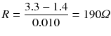
The voltage drop V
F
of an LED varies with the color of the device [1]. A green LED is listed between 1.9 and 4 volts, while a red LED is 1.6 to 2 volts. Since you’re using a +3.3V supply, this means you only have a difference of V
CC
– V
F
= 3.3 – 1.9 = 1.4 Volts for green LEDs and 3.3 – 1.6 = 1.7 Volts for red. The dropping resistor you need can be determined with the following:

Many LEDs will use about 10mA, which is well within the PCF8574 sinking capability. So, calculate the following:
The closest E12 resistance value to this is 180Ω. If you have trouble finding of that value, you can safely go up to 200Ω or even go lower.
With R2 of Figure 13-2 set to a value of 180Ω, the resistor wired to the +3.3V side, and the other end wired to the LED, connect the green LED cathode to IC2’s P0. Do the same for the red LED, except that the LED cathode goes to P1. Before you present the software, let’s prove that the hardware is good. Turn on the green LED (note that the I2C address is 0x21 this time for IC2).
$ i2cset -y 1 0x21 0xFEIf everything is wired correctly, the green LED should light, and the red one should remain dark. Now enable the red LED.
$ i2cset -y 1 0x21 0xFDThe red LED should light, and the green one should be dark. Finally, let’s light both.
$ i2cset -y 1 0x21 0xFCTo turn them both off again, write the value 0xFF to the port. Note that only the last two bits actually matter here as far as the LEDs are concerned.
Combination Lock
With the LEDs installed and tested, you can turn your attention to the combination lock software. The program must implement a state machine based upon key press events. The state machine you’re going to use is as follows:
The initial state is that no keys have pressed yet. Clear the buffer of key codes.
Wait for a key press. Proceed to the next step when it arrives.
Add a key code to the buffer.
Have four keys been pressed? If not, go to back to step 2.
If four keys have been pressed, is the combination correct? If not, light the red LED and go to step 1.
The combination is correct: light the green LED to announce the unlocking of the device.
Has a key been pressed? If so, turn off the green LED and return to step 1. Otherwise, continue to wait.
The program combo.cpp located in the ./keypad subdirectory implements this overall procedure, except that it checks the combination code as the keys are entered. You’ll examine that later.
Figure 13-7 illustrates my breadboard arrangement. Don’t be intimidated by the number of wires. Most of the wires (most of them white) are wires to ground for the PCF8574 address pins. The remaining white wires take connections from the keypad to IC1.
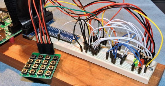
Figure 13-7. A breadboarded circuit for the keypad.cpp and combo.cpp programs
With the hardware ready, run the program combo, as shown here:
$ ./combo*** LOCKED ***code[0] = 7D (S14)code[1] = BB (S11)code[2] = DD (S6)code[3] = ED (S2)*** FAILED ****** LOCKED ***code[0] = BE (S9)code[1] = D7 (S8)code[2] = DD (S6)code[3] = DB (S7)*** UNLOCKED ****** LOCKED ***^C
The session output helps display state information as the code runs. A full implementation would provide some kind of feedback for each key as it is entered. You could, for example, use the remaining ports of IC2 to light an LED for each of the four codes. This is left as an exercise for you.
Initially, the session reports that the lock is “locked.” As each key is pressed, the scan code and the key name are displayed (for demonstration purposes). At the end of four codes, the lock either fails to unlock (red LED) or becomes unlocked (green LED).
The first attempt shown in the session output has an entry of S14, S11, S6, and S2 before the red LED comes on and the session reports “failed.” At this point, the state machine restarts, allowing entry of a new code.
The red LED is permitted to stay on until the entry of the first key code. You’ll see that in the code later in this chapter. In the second attempt, keys S9, S8, S6, and S7 are pressed to successfully unlock the device. The green LED will remain lit until another (any) key is pressed. At that point, the green LED is turned off, and the device enters a locked state once again.
The main Program
The main program has changed to implement a key press state machine. This is presented in Listing 13-5.
Listing 13-5. The combo.cpp Main Program
140 int141 main(int argc,char **argv) {142 static uint8_t code[4] = {143 // 9, 8, 6 7:144 0xBE, 0xD7, 0xDD, 0xDB145 };146 uint8_t keypad, kx;147 bool matched;148149 // Open the I2C bus150 i2c_fd = open(i2c_device,O_RDWR);151 if ( i2c_fd == -1 ) {152 fprintf(stderr,"%s: opening %s\n",153 strerror(errno),154 i2c_device);155 exit(1);156 }157158 i2c_write(i2c_led_addr,0xFF); // Both LEDs off159160 for (;;) {161 puts("*** LOCKED ***");162163 // Wait for entry of all four codes:164 matched = true;165 for ( kx=0; kx<4; ++kx ) {166 keypad = get_key_code();167 printf("code[%u] = %02X (%s)\n",168 kx,keypad,169 key_lookup(keypad));170 if ( keypad != code[kx] )171 matched = false;172 if ( kx == 0 ) {173 // All LEDs off174 i2c_write(i2c_led_addr,0xFF);175 }176 }177 if ( !matched ) {178 // Failed: Red LED + start over179 i2c_write(i2c_led_addr,∼red_led);180 puts("*** FAILED ***");181 continue;182 }183 // Code matched: unlock184 i2c_write(i2c_led_addr,∼green_led);185186 // Wait for any key code to lock187 // and restart188 puts("*** UNLOCKED ***");189 get_key_code();190 i2c_write(i2c_led_addr,0xFF);191 }192193 return 0;194 }
Lines 142 to 145 define the secret passcode to unlock this device. These are scan codes representing S9, S8, S6, and S7. Line 158 initializes the LEDs to the off state.
The main loop begins in line 160, repeating forever until the program is cancelled with Control-C. Line 161 announces the locked state to the session output and initializes the bool variable matched to true. As each key code is entered, if there is any mismatch, then this variable will be set to false.
Lines 165 to 176 accept input key codes. The code is accepted in line 166 and checked against the passcode in line 170. The variable kx tracks the key number from 0 to 3. If there is a mismatch between any of the codes, the matched variable is set to false in line 171. By the time the end of the loop is reached (line 177), this will tell you whether the code was correct.
If the code didn’t match, you activate the red LED in line 179. Note the inverted value of ∼red_led. The LED is lit when the red LED bit is set to 0. The continue statement returns control to the top of the main loop for another attempt. The red LED is allowed to remain lit while this loop restarts. However, lines 172 to 175 force all LEDs off, once the first key press is received.
When the correct code is entered, control passes to line 184 to light the green LED. The lock is announced unlocked at line 188, and the code waits for a key press (of any key) at line 189. Once a key is pressed, the lock is relocked again, and the green LED is extinguished in line 190.
The get_key_code Function
The remainder of the combo.cpp source code remains the same as the keypad.cpp program. The exception to this is that what was the main loop in keypad.cpp has been moved into a function in combo.cpp. Listing 13-6 illustrates the function named get_key_code.
Listing 13-6. Function get_key_code
111 uint8_t112 get_key_code() {113 uint8_t keypad, row;114115 // Wait for key release:116 while ( (i2c_read(i2c_keypad_addr) & 0x0F) != 0x0F )117 usleep(20000);118119 // Wait for key press:120 for (;;) {121 // Scan each keypad row:122 for ( row=0x10; row != 0; row <<= 1 ) {123 // Drive the row select124 i2c_write(i2c_keypad_addr,∼row);125126 // Read the column inputs127 keypad = i2c_read(i2c_keypad_addr);128129 if ( (keypad & 0x0F) != 0x0F )130 return keypad;131 usleep(20000);132 }133 }134 }
This code is almost unchanged from what was presented earlier. However, there is one major change to be explained.
In the keypad.cpp program, once you had a keypress, you remained in a loop waiting for the key to be released. In combo.cpp, you want the lock to unlock the very moment the last correct key code is pressed. So, you return the keycode immediately at line 130. However, this necessitates that you wait for a key release when the function is called later (lines 116 to 117).
While this change isn’t absolutely essential, most people expect an action to occur at the moment of the key being pressed. For a lock, you could choose to do this when the key is released instead.
Interrupts
One concept that I didn’t have the space to explore was the concept of the interrupt (/INT) pin on the PCF8574. With the current programs, it must continually poll the PCF8574 chips to see whether there is a key press. The interrupt pin of the PCF8574 chip can signal a data change to a Pi GPIO input. A poll of the GPIO pin is quick and cheap and leaves the I2C bus available for other traffic.
Additionally, each /INT output is driven by an open collector transistor. This permits two or more /INT signals to be wired together so that only one interrupt signal line is required. This requires only one pull-up resistor on the line. I encourage you to read the datasheets and explore this important functionality.
Summary
You’ve reached the end of this book; all good things must come to an end. I hope that this book has inspired you to try some hardware attached to the Raspberry Pi and come up with ideas of your own. A hobbyist can have fun just reproducing “how to” articles, attaching Pi hats, and so on. But the real fun is in taking an idea and designing the interfaces yourself!
Bibliography
Poole, By Ian. “LED Characteristics & Colours.” LED Characteristics and Colours. Accessed November 05, 2016. < www.radio-electronics.com/info/data/semicond/leds-light-emitting-diodes/characteristics.php >.