While it is possible to add input and output ports with various CMOS chips, sometimes more flexibility is required. The pin functions of chips like the 74HC165 and 74HC595 are fixed as input or output. Sometimes it is desirable to be able to configure them as required like the Raspberry Pi’s own GPIO ports. This chapter will examine the Microchip MCP23017 peripheral chip, which can offer any combination of 16 GPIO ports (in DIP form), each of which can be individually configured as input or output. Figure 11-1 illustrates the chip sitting on a breadboard.
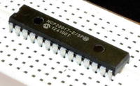
Figure 11-1. An MCP23017 chip on the breadboard
MCP23017
Microchip’s MCP23017 can be purchased for as little as $1.99; it communicates with the Pi over the I2C bus. Because the I2C bus requires only two power lines and two data lines, it needs only a four-conductor ribbon cable and thus can cover some distance. Figure 11-2 shows the schematic pinout.
Figure 11-2. MCP23017 pinout
The active low RESET pin can be tied to the supply if not required, since a software reset is still possible. The signal forces a chip reset like the name implies.
The SCL and SDA are the two I2C communication connections. Chip inputs A0 through A2 allow you to configure the I2C address for the chip. Grounding them gives the chip address 0x20. Table 11-1 summarizes the addresses.
Table 11-1. MCP23017 I2C Addresses
A2 | A1 | A0 | Address (Hex) |
|---|---|---|---|
0 | 0 | 0 | 0x20 |
0 | 0 | 1 | 0x21 |
0 | 1 | 0 | 0x22 |
0 | 1 | 1 | 0x23 |
1 | 0 | 0 | 0x24 |
1 | 0 | 1 | 0x25 |
1 | 1 | 0 | 0x26 |
1 | 1 | 1 | 0x27 |
The INTA and INTB output pins are optional signals that can provide interrupt notification to the Raspberry Pi over one or two GPIO ports. The remaining pins GPA0 through GPA7 and GPB0 through GPB7 provide 16 more GPIO ports, which are under software configuration control.
Wiring
Figure 11-3 shows the wiring necessary to attach the MCP23017 to the Raspberry Pi. On the breadboard, simply wire the T-Cobbler connections marked SCL and SDA to pins 12 and 13, respectively.
Figure 11-3. MCP2301 wired to the Raspberry Pi
Make certain that the RESET pin is also wired to the supply so that it doesn’t become active. For simplicity and agreement with the provided software, connect inputs A0 through A2 to ground. This configures the chip to respond to I2C address 0x20. Signals INTA and INTB are outputs and can be ignored for the moment.
After reset, the MCP23017 chip automatically configures all the GPAx and GPBx pins as inputs, without a pull-up resistor. This is not ideal because this leaves the CMOS inputs floating. But for this initial experiment, the chip should tolerate it.
If you haven’t already done so, install i2c-tools.
$ sudo apt-get install i2c-toolsOnce installed, then list your I2C buses.
$ i2cdetect -lIf nothing is displayed, then you need to make sure that the I2C drivers get loaded. The new kernels now use the /boot/config.txt file to enable I2C support. Edit the file so that the i2c line is uncommented as follows:
# Uncomment some or all of these to enable the optional hardware interfacesdtparam=i2c_arm=on#dtparam=i2s=on#dtparam=spi=on
Save your changes and reboot to try again.
sudo /sbin/shutdown -r nowAfter the reboot, list the I2C buses again.
$ i2cdetect -li2c-1 i2c 3f804000.i2c I2C adapter
From this, you now see i2c-1 is available as expected. Now probe for your MCP23017 device. The command-line argument 1 shown next indicates to scan bus i2c-1.
$ i2cdetect -y 10 1 2 3 4 5 6 7 8 9 a b c d e f00: -- -- -- -- -- -- -- -- -- -- -- -- --10: -- -- -- -- -- -- -- -- -- -- -- -- -- -- -- --20: 20 -- -- -- -- -- -- -- -- -- -- -- -- -- -- --30: -- -- -- -- -- -- -- -- -- -- -- -- -- -- -- --40: -- -- -- -- -- -- -- -- -- -- -- -- -- -- -- --50: -- -- -- -- -- -- -- -- -- -- -- -- -- -- -- --60: -- -- -- -- -- -- -- -- -- -- -- -- -- -- -- --70: -- -- -- -- -- -- -- --
If all was successful, you should see a “20” listed among the hyphens. This tells you that the device is reachable on the i2c-1 bus.
Output GPIO Experiment
With your breadboard wired according to Figure 11-3, you can perform a GPIO output test. Enter the subdirectory mcp23017 in the source code and type make to build the programs there. Once that is done, you can run the output test.
$ ./mcp_outGPIOA = 0x0BGPIOB = 0xC1
This program will write the hexadecimal value 0x0B to GPIO port A and 0xC1 to GPIO port B. You’ll examine the source code later.
With your DMM or an LED and dropping resistor (refer to Figure 10-4 in Chapter 10), probe the MCP23017 GPIO output pins. With this program run, you should observe the values listed in Table 11-2. Pay special attention to the chip pin numbers when wiring or taking readings. The pins for GPIOA and GPIOB are physically laid out in reverse order from each other.
Table 11-2. Output Readings of the MCP23017 After Running mcp_out
GPIO A Pin | Port | Result | GPIO B Pin | Port | Result |
|---|---|---|---|---|---|
28 | GPA7 | Low | 8 | GPB7 | High |
27 | GPA6 | Low | 7 | GPB6 | High |
26 | GPA5 | Low | 6 | GPB5 | Low |
25 | GPA4 | Low | 5 | GPB4 | Low |
24 | GPA3 | High | 4 | GPB3 | Low |
23 | GPA2 | High | 3 | GPB2 | Low |
22 | GPA1 | Low | 2 | GPB1 | Low |
21 | GPA0 | High | 1 | GPB0 | High |
Figure 11-4 illustrates my breadboard setup. One nice aspect of I2C is the wiring simplicity. The plastic DIP (PDIP) form of the chip consists of 28 pins. The pin arrangement is somewhat unusual in that the VDD (+3.3V) goes to pin 9, while pin 10 (VSS) is the ground connection. Be sure that the RESET pin is wired high or it will sporadically reset or stay in reset mode. The remaining white wires shown in Figure 11-4 ground A0 through A2 so that the I2C address is established as hex 0x20.
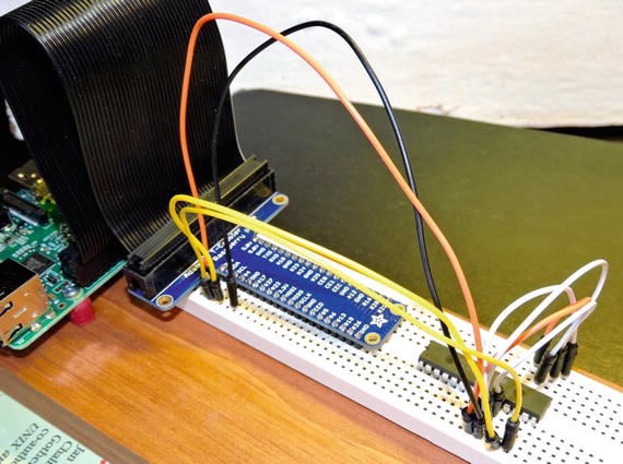
Figure 11-4. MCP23017 breadboard setup
Input Experiment
With no change to the breadboard circuit, you can now run an input experiment. This is one area that the I2C peripheral excels: it can software reconfigure the 16 GPIO pins as outputs or inputs. With the program compiled earlier (in the mcp23017 subdirectory), you can just invoke mcp_in.
$ ./mcp_inGPIOA = 0xFF, GPIOB = 0xFFGPIOA = 0xBF, GPIOB = 0xFFGPIOA = 0xFF, GPIOB = 0xFFGPIOA = 0xDF, GPIOB = 0xFFGPIOA = 0xFF, GPIOB = 0xFFGPIOA = 0xDF, GPIOB = 0xFFGPIOA = 0xFF, GPIOB = 0xFFGPIOA = 0xFF, GPIOB = 0xFDGPIOA = 0xFF, GPIOB = 0xFFGPIOA = 0xFF, GPIOB = 0xFDGPIOA = 0xFF, GPIOB = 0xFFGPIOA = 0xFF, GPIOB = 0xFDGPIOA = 0xFF, GPIOB = 0xFFGPIOA = 0xFF, GPIOB = 0xFD
Initially, you will see only the following line:
GPIOA = 0xFF, GPIOB = 0xFFAfter you see this initial report, ground one end of a Dupont wire (to the Pi). With the other end of the wire, touch or insert the wire in various places for GPIO A or GPIO B. Be careful not to touch any other pins, however. As you do this, changes in the input port (or ports) will be reported on your console session. Sometimes there will be “stutter” output. This is because of the speed of the Pi and the contact bouncing or scratching that occurs.
When the joy of the experiment diminishes, press ^C (Control-C) to end the program.
Software Operations
The flexibility of the MCP23017 GPIO peripheral requires extra responsibility on the software side. To complicate things further, Microchip provides two methods for addressing registers within its chip. This is configured by the IOCON.BANK bit. This chapter assumes IOCON.BANK=0, including the software provided. This results in the registers being laid out as in Table 11-3.
Table 11-3. MCP23017 Register Addresses
Register Name | Hexadecimal Address | Register Description |
|---|---|---|
IODIRA | 00 | I/O Direction for GPIO A |
IODIRB | 01 | I/O Direction for GPIO B |
IPOLA | 02 | Input Polarity for GPIO A |
IPOLB | 03 | Input Polarity for GPIO B |
GPINTENA | 04 | Interrupt on Change for GPIO A |
GPINTENB | 05 | Interrupt on Change for GPIO B |
DEFVALA | 06 | Default Compare for Interrupt GPIO A |
DEFVALB | 07 | Default Compare for Interrupt GPIO B |
INTCONA | 08 | Interrupt on Change Control GPIO A |
INTCONB | 09 | Interrupt on Change Control GPIO B |
IOCON | 0A | Configuration Control |
IOCON | 0B | |
GPPUA | 0C | Pull-up Resistor for GPIO A |
GPPUB | 0D | Pull-up Resistor for GPIO B |
INTFA | 0E | Interrupt Flags for GPIO A |
INTFB | 0F | Interrupt Flags for GPIO B |
INTCAPA | 10 | Interrupt Capture for GPIO A |
INTCAPB | 11 | Interrupt Capture for GPIO B |
GPIOA | 12 | GPIO A |
GPIOB | 13 | GPIO B |
OLATA | 14 | Output Latch for GPIO A |
OLATB | 15 | Output Latch for GPIO B |
In this discussion, please keep in mind that the I2C and register addresses are two different entities. The register address allows you to access registers within the peripheral, while the I2C address allows you to select the peripheral device.
Essentially, Table 11-3 shows that the least significant bit in this mode selects GPIO A or B, with the register selection shifted left one bit. Hence, within the program, you make use of the following macros:
#define IODIR 0#define IPOL 1#define GPINTEN 2#define DEFVAL 3#define INTCON 4#define IOCON 5#define GPPU 6#define INTF 7#define INTCAP 8#define GPIO 9#define OLAT 10#define GPIOA 0#define GPIOB 1#define MCP_REGISTER(r,g) (((r)<<1)|(g))
Using these macros, you can select register IODIR for GPIOB using MCP_REGISTER(IODIR,GPIOB) in the code.
I2C Header Files
Under Raspbian Linux, you need certain header files for performing I2C I/O.
#include <sys/ioctl.h>#include <linux/i2c.h>#include <linux/i2c-dev.h>
These provide structure definitions and macros necessary to issue your I2C I/O operations.
Opening the I2C Driver
When the i2cdetect -l command was run, you saw that the i2c-1 bus was available. You access this bus driver with the path /dev/i2c-1. Consequently, you use the open(2) system call to gain access to the driver. Listing 11-1 is a code snippet from mcp_out.cpp showing the open call.
Listing 11-1. Opening the I2C Bus
036 static const char *i2c_device = "/dev/i2c-1";037 static int i2c_fd = -1;093 int094 main(int argc,char **argv) {095 int rc;096097 i2c_fd = open(i2c_device,O_RDWR);098 if ( i2c_fd == -1 ) {099 fprintf(stderr,"%s: opening %s\n",100 strerror(errno),101 i2c_device);102 exit(1);103 }
Line 036 defines the character string i2c_device path to be opened. The opened file descriptor is returned in variable i2c_fd if successful, or the value –1 is returned if there is a failure. The file descriptor acts as a handle to the Linux driver. Lines 098 through 103 report the error, if the open is unsuccessful.
I2C Write
Writing to an I2C device under Linux is fairly straightforward, once you’ve seen how it is done. Listing 11-2 shows the function i2c_write, which is used to write 1 to 2 bytes to the MCP23017 peripheral chip.
Listing 11-2. The I2C Write Routine
062 static int063 i2c_write(int addr,int reg,int ab,uint8_t byte) {064 struct i2c_rdwr_ioctl_data msgset;065 struct i2c_msg iomsgs[1];066 uint8_t reg_addr = MCP_REGISTER(reg,ab);067 uint8_t buf[2];068 int rc;069070 buf[0] = reg_addr;071 buf[1] = byte;072073 iomsgs[0].addr = unsigned(addr);074 iomsgs[0].flags = 0;075 iomsgs[0].buf = buf;076 iomsgs[0].len = 2;077078 msgset.msgs = iomsgs;079 msgset.nmsgs = 1;080081 rc = ioctl(i2c_fd,I2C_RDWR,&msgset);082 return rc < 0 ? -1 : 0;083 }
The argument addr is the I2C address of the MCP23017 (in this case 0x20). The argument reg selects the MCP23017 register that you want to target, while ab selects GPIO A or GPIO B. The value to be written is provided in argument byte.
The Linux structure i2c_rdwr_ioctl_data is used to pass your request to the driver. The array of i2c_msg structures allows you to define the I2C operations required. In this case, you want to perform only one write, so the array consists of a single structure.
Line 066 computes the peripheral register address using the MCP_REGISTER macro. The data for the I2C message is created in lines 070 and 071. The message is the MCP23017 register you want to change (buf[0]) and then the value to assign to it (buf[1]).
Lines 073 to 076 describe the I2C operation. Line 073 tells the I2C driver the peripheral’s I2C address (0x20). Line 074 indicates that this is a write operation because it is missing the flag I2C_M_RD, which is defined as a Linux macro. The data buffer address is provided in line 075, while the length of the data in bytes is described in line 076. These lines describe everything necessary for one I2C write message.
Because there can be several I2C messages performed at once, lines 078 and 079 are necessary. Line 078 describes how to locate the first I2C operation (described by struct i2c_msg). Line 079 in this case will inform the driver that only one I2C message is to be processed.
Line 081 is where you pass this assembled request to the kernel driver. If the operation fails for any reason, the return code rc will have the value –1 assigned to it. The first argument is the open file descriptor acting as a handle to the driver. The second argument, I2C_RDWR, indicates that you want to perform an I2C I/O operation. The last argument is a pointer to the “message set” to be performed.
I2C Read
Reading from an I2C device is almost the same as writing, but many devices need to know which peripheral register to read from. For this reason, you use a write and then read with the MCP23017 chip. Listing 11-3 shows the read routine used in the program mcp_in.cpp.
Listing 11-3. I2C Read Routine
062 int063 i2c_read_data(int addr,int ab,uint8_t& byte) {064 struct i2c_rdwr_ioctl_data msgset;065 struct i2c_msg iomsgs[2];066 uint8_t txbuf[1];067 int rc;068069 txbuf[0] = MCP_REGISTER(GPIO,ab);070071 iomsgs[0].addr = iomsgs[1].addr = unsigned(addr);072 iomsgs[0].flags = 0; // Write073 iomsgs[0].buf = txbuf;074 iomsgs[0].len = 1;075076 iomsgs[1].flags = I2C_M_RD; // Read077 iomsgs[1].buf = &byte; // Pass back data byte078 iomsgs[1].len = 1;079080 msgset.msgs = iomsgs;081 msgset.nmsgs = 2;082083 rc = ioctl(i2c_fd,I2C_RDWR,&msgset);084 return rc < 0 ? -1 : 0;085 }
In this routine you see that the setup of the message structures is almost the same. Line 062, however, declares an array of two i2c_msg structures, because you need to perform two operations.
Lines 070 through 074 set up a write of 1 byte, which simply contains the peripheral register that you want to read (define in line 069). This write operation will simply write the register to be selected to the MCP23017 device prior to the read operation.
Lines 076 through 078 set up a read of 1 byte into the variable byte. Here the value byte is passed using a C++ reference type. This allows the changed value to be passed back to the caller as a read byte.
Line 081 informs the driver that there are two I/O operations and ties everything together in the variable msgset. If the call to ioctl(2) in line 083 is successful, the peripheral register will be written to the device followed by a read. The sequence causes the indicated peripheral register to be read and returned.
Configuration
The programs mcp_out.cpp and mcp_in.cpp configure the MCP23017 peripheral through a series of I2C writes in the main program. Listing 11-4 shows a code snippet from the main program mcp_in.cpp.
Listing 11-4. Main Program Configuration in mcp_in.cpp
129 rc = i2c_write_both(i2c_addr,IOCON,0b01000100); // MIRROR=1,ODR=1130 assert(!rc);131132 rc = i2c_write_both(i2c_addr,GPINTEN,0x00); // No interrupts enabled133 assert(!rc);134135 rc = i2c_write_both(i2c_addr,DEFVAL,0x00); // Clear default value136 assert(!rc);137138 rc = i2c_write_both(i2c_addr,OLAT,0x00); // OLATx=0139 assert(!rc);140141 rc = i2c_write_both(i2c_addr,IPOL,0b00000000); // No inverted polarity142 assert(!rc);143144 rc = i2c_write_both(i2c_addr,GPPU,0b11111111); // Enable all pull-ups145 assert(!rc);146147 rc = i2c_write_both(i2c_addr,IODIR,0b11111111); // All are inputs148 assert(!rc);
Each of these writes uses a routine called i2c_write_both. This convenience routine simply performs a call to i2c_write of the same values, for GPIO A and GPIO B, reducing the amount of code. Line 147, for example, configures the MCP23017 register IODIR. When the bits in this register are written as 1, they configure the corresponding GPIO pin as an input. You can find more information about configuration in the Microchip datasheet (you can Google MCP23017 datasheet to find it).
Interrupt Capability
Earlier you saw a demonstration of reading MCP23017 GPIO inputs. But if the inputs are attached to push buttons, for example, how does your program stay informed without constantly polling the peripheral? You could continuously perform I2C read operations as the mcp_in.cpp program does, but this keeps the I2C bus very busy.
Microchip provides a feature in the MCP23017 peripheral to provide one or two interrupt signals for input signal changes. You may configure it for separate GPIO A and B interrupts, or you may configure it to use one pin for both. Pins 19 and 20 of the chip provide the interrupt signals.
The next demonstration will use one pin (INTA pin 20) to signal a change of GPIO input, whether for GPIO A or B. To do this, you must the set the peripheral’s configuration.
IOCON.MIRROR = 1 (INTA represents both GPIO A and B).
IOCON.ODR = 0 (when true, the INTA is in “open drain” configuration)
IOCON.INTPOL = 0 (you’re going to make the INTA pin active low; this applies only when ODR=0).
GPINTEN.BPINTx bits 0 through 7 enable interrupts for each pin (1=enabled)
INTCON.IOCx bits 0 through 7 are either:
Compared to the DEFVAL register (when set to 1)
Compared to self (when set to 0)
DEFVAL.DEFx bits 0 through 7 set the compare value for interrupts (optionally)
The DEFVAL settings apply only if you enable DEFVAL in IOCON.IOCx. For example, if IOCON.IOC2 for GPIOB is set to 1, then DEFVAL.DEF2 is used to compare against the GPIO B input 2. If the values differ, an interrupt is generated.
You’re going to use INTCON.IOCx=0 so that the interrupt occurs on any change in the input signal. In this configuration, the DEFVAL bit setting has no influence. You can think of this configuration as comparing the input against its last known value.
The program being used for this experiment is named mcp_int.cpp. By default, this program assumes you have connected GPIO#5 to the MCP23017 INTA pin 20. If you need to change this to something else, then this is the line you need to edit:
041 static int gpio_inta = 5; // GPIO for INTA signalThe main routine configures the peripheral for interrupts as described earlier. This is illustrated in Listing 11-5.
Listing 11-5. MCP23017 Interrupt Configuration
144 rc = i2c_write_both(i2c_addr,IOCON,0b01000000); // MIRROR=1,ODR=0,INTPOL=0145 assert(!rc);146147 rc = i2c_write_both(i2c_addr,IODIR,0xFF); // All are inputs148 assert(!rc);149150 rc = i2c_write_both(i2c_addr,INTCON,0x00); // Interrupts compare to self151 assert(!rc);152153 rc = i2c_write_both(i2c_addr,GPINTEN,0xFF); // All interrupts enabled154 assert(!rc);155156 rc = i2c_write_both(i2c_addr,IPOL,0x00); // No inverted input polarity157 assert(!rc);158159 rc = i2c_write_both(i2c_addr,GPPU,0xFF); // Enable all pull-ups160 assert(!rc);
The comments indicate the configuration values being set. For simplicity, mcp_int.cpp sets all GPIO pins as inputs. Once all the configuration is performed, the main program enters its main loop, shown in Listing 11-6.
Listing 11-6. Main Loop for Interrupt Processing
162 {163 uint8_t gpioa, gpiob, inta, intf_a = 0, intf_b = 0;164165 rc = i2c_read_data(i2c_addr,GPIOA,GPIO_,gpioa);166 assert(!rc);167168 rc = i2c_read_data(i2c_addr,GPIOB,GPIO_,gpiob);169 assert(!rc);170171 printf("GPIOA 0x%02X INTFA 0x%02X, GPIOB 0x%02X INTFB 0x%02X\n",172 gpioa, intf_a,173 gpiob, intf_b);174175 for (;;) {176 inta = gpio.read(gpio_inta);177 if ( inta != 0 ) {178 // No interrupt179 usleep(1);180 continue;181 }182183 // Process interrupt184185 rc = i2c_read_data(i2c_addr,GPIOA,INTF,intf_a);186 assert(!rc);187188 rc = i2c_read_data(i2c_addr,GPIOB,INTF,intf_b);189 assert(!rc);190191 rc = i2c_read_data(i2c_addr,GPIOA,INTCAP,gpioa);192 assert(!rc);193194 rc = i2c_read_data(i2c_addr,GPIOB,INTCAP,gpiob);195 assert(!rc);196197 printf("GPIOA 0x%02X INTFA 0x%02X, GPIOB 0x%02X INTFB 0x%02X\n",198 gpioa, intf_a,199 gpiob, intf_b);200 }201 }
Lines 165 to 173 simply report the current state of the MCP23017 inputs prior to entering the loop. The loop, starting in line 175, polls Raspberry Pi GPIO (#5) to see whether the chip is reporting an interrupt. If the INTA line is high, there is no interrupt being reported, so a short sleep is performed and the loop is restarted (lines 177 to 181).
If the Raspberry Pi GPIO (#5) is low, this indicates that one or both of the MPC23017 ports has registered a change on an input pin. Lines 185 to 189 read the INTF register for GPIO A and GPIO B. This register sets a 1 bit where an input value has changed. Lines 191 to 195 read the interrupt capture register for GPIO A and B. These registers reflect the input line states at the time of the interrupt. Lines 197 to 199 simply report the changes.
Figure 11-5 shows how to wire the circuit for the interrupt test. The only new connection is the connection going from the Raspberry Pi’s GPIO #5 to the INTA pin 20 of the peripheral.
Figure 11-5. MCP23017 wired for interrupt signaling
After wiring according to Figure 11-5, run the program mcp_int. All chip pins are configured as input with a pull-up resistor so that they will read high with no connections to them. While the program was running in the following session, I touched a ground wire to GPA5 (bit 5 of GPIOA on pin 28) in the example session shown here:
$ ./mcp_intGPIOA 0xFF INTFA 0x00, GPIOB 0xFF INTFB 0x00GPIOA 0xDF INTFA 0x20, GPIOB 0xFF INTFB 0x00GPIOA 0xFF INTFA 0x20, GPIOB 0xFF INTFB 0x00GPIOA 0xFF INTFA 0x20, GPIOB 0xFF INTFB 0x00GPIOA 0xFF INTFA 0x20, GPIOB 0xFF INTFB 0x00
The first line is simply the initial reported setting. The program will wait there until you do something (like grounding an input). The second line reports that GPIOA captured the hex value DF as part of the change (in the first line reported as FF). The INTFA register reports 20, indicating the bit that changed (bit 5). This confirms that the GPA5 went from a 1 bit to a 0 bit.
Because of the rate of changes, sometimes you will register changes but not see them in the capture register. In the example session, INTFA continues to register the fact that bit 5 changed but showed no change in the captured value (FF). Because of contact bouncing (of my Dupont wire), the chip registered a change, but the state of the input changed back to a 1 bit by the time the capture was made.
Interrupt Profit and Loss
What did you gain from the use of the INTA pin? This pin is intended by Microchip for use as a real interrupt signal for a microcomputer. Here you attached it to the Pi’s GPIO #5 and polled that signal for changes. So, what did you gain?
While you still utilized polling, you polled a single Pi GPIO, which is far cheaper than continuously sending I2C read commands to the bus. By polling a Pi GPIO, you freed up available bandwidth on the I2C bus, which might be used for other devices. The I2C bus was used only when needed.
Summary
While the 74HC165 and 74HC595 parts were easy to use, they were not reconfigurable. The MCP23017, however, offers 16 fully software configurable GPIO pins. The price of this is the additional software complexity. The chip also provides additional interrupt input processing that is absent in the simpler 74HC165 and 74HC595 parts. Finally, the ability to connect several devices to the I2C bus makes the MCP23017 a flexible peripheral, whether the device is local or remote to the Raspberry Pi.