© Warren Gay 2018
Warren GayAdvanced Raspberry Pihttps://doi.org/10.1007/978-1-4842-3948-3_7

7. USB

Warren Gay1 
(1)
St. Catharine’s, Ontario, Canada
 

The USB port has become ubiquitous in the digital world, allowing the use of a large choice of peripherals. The Raspberry Pi models support one to four USB ports, depending upon the model.

This chapter briefly examines some power considerations associated with USB support and powered hubs. The remainder of this chapter examines the device driver interface available to the Raspbian Linux developer by programming access to an EZ-USB FX2LP developer board.

Power

Very early models of the Raspberry Pi limited each USB port to 100 mA because of the polyfuses on board. Revision 2.0 models and later did away with these, relieving you from the different failures that could occur. The USB 2 power limit is 500 mA from a single port. Keep this in mind when designing your IoT (internet of things).

Note

Wireless USB adapters consume between 350 mA and 500 mA.

Powered Hubs

Some applications will require a powered USB hub for high-current peripherals. This is particularly true for wireless network adapters, since they require up to 500 mA. But a USB hub requires coordination with the Linux kernel and thus requires software support. A number of hubs have been reported not to work. The following web page is a good resource for listing hubs that are known to work with Raspbian Linux:

http://elinux.org/RPi_Powered_USB_Hubs
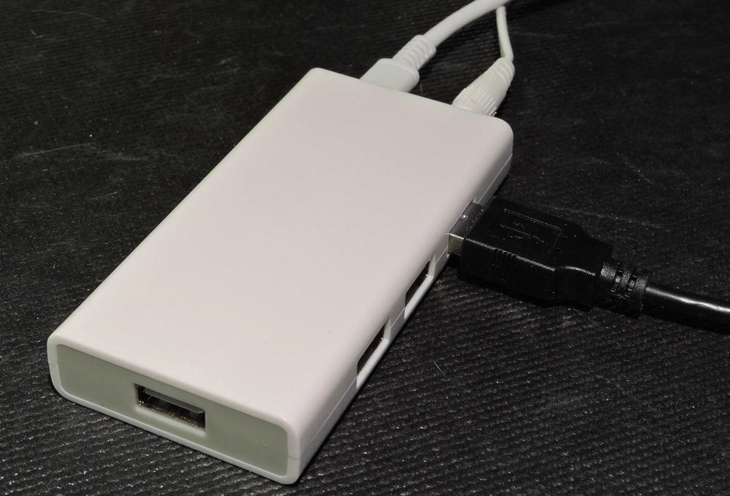
With the powered USB hub plugged in, you can list the USB devices that have registered with the kernel by using the lsusb command:
$ lsusb
Bus 001 Device 008: ID 1a40:0101 Terminus Technology Inc. Hub
Bus 001 Device 007: ID 1a40:0101 Terminus Technology Inc. Hub
Bus 001 Device 004: ID 045e:00d1 Microsoft Corp. Optical Mouse with Tilt Wheel
Bus 001 Device 005: ID 04f2:0841 Chicony Electronics Co., Ltd HP Multimedia Keyboard
Bus 001 Device 006: ID 0424:7800 Standard Microsystems Corp.
Bus 001 Device 003: ID 0424:2514 Standard Microsystems Corp. USB 2.0 Hub
Bus 001 Device 002: ID 0424:2514 Standard Microsystems Corp. USB 2.0 Hub
Bus 001 Device 001: ID 1d6b:0002 Linux Foundation 2.0 root hub
The first two in the example session show my Terminus Technology Inc. powered hub, registered after it was plugged into the Pi. The mouse (Microsoft) and keyboard (HP) are two peripherals plugged into the Pi. The remaining are drivers supporting the Pi hub for the USB ports. The hub used in this session is shown in Figure 7-1.
../images/326071_2_En_7_Chapter/326071_2_En_7_Fig1_HTML.jpg
Figure 7-1

A powered USB hub

EZ-USB FX2LP

In this chapter, we’re not just going to talk about USB. Instead we’re going to interface your Pi to an economical board known as the EZ-USB FX2LP, which is available on eBay for the low cost of about $4. The chip on board is CY7C68013A and is manufactured by Cypress. If you do an eBay search for “EZ-USB FX2LP board,” you should be able to find several sources.

There is an FX3LP chip available but it is not hobby priced. Furthermore, it requires special instructions to get driver support installed. If you stay with the FX2LP, the Raspbian Linux kernel drivers should automatically support it.

Figure 7-2 illustrates the unit that the author is using, with a USB Mini-b (5-pin) cable plugged in. You will need to order the cable if you don’t already own one. By using a USB developer board, you can control both ends of the USB connection. Yet the EZ-USB is simple enough to use, allowing us to avoid rocket science.
../images/326071_2_En_7_Chapter/326071_2_En_7_Fig2_HTML.jpg
Figure 7-2

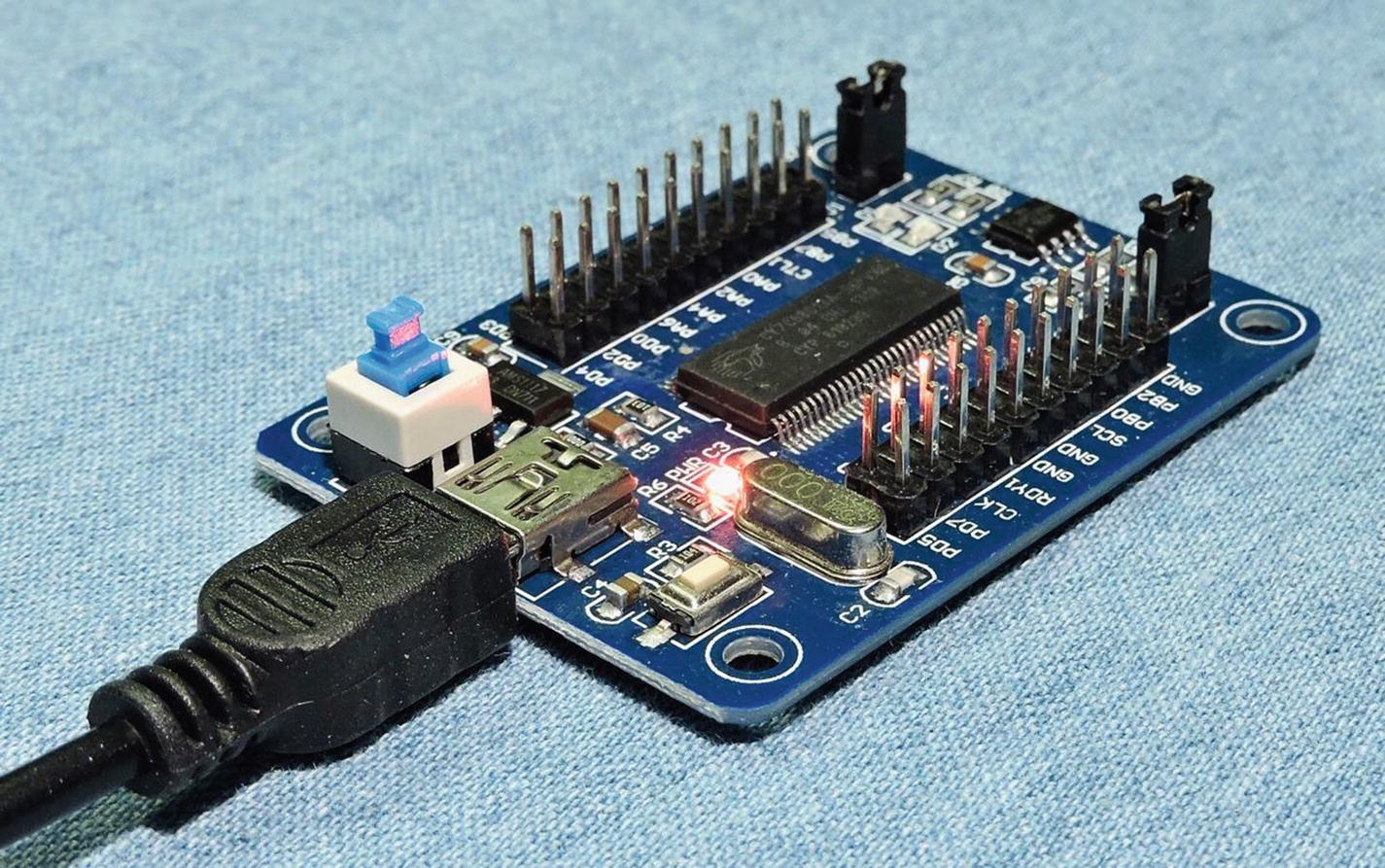
The FX2LP EZ-USB developer board

When you first get the device, you should be able to test it simply by plugging it into a Pi USB port. Then use the lsusb command to see if the Linux kernel sees it (the line shown below is wrapped to make it fit the page width).
$ lsusb
Bus 001 Device 011: ID 04b4:8613 Cypress Semiconductor Corp. CY7C68013 EZ-USB FX2 \
        USB 2.0 Development Kit
...

Device Introduction

Anchor Chips Inc. was acquired in 1999 by Cypress Semiconductor Corp.8 Anchor had designed an 8051 chip that allowed software to be uploaded into its SRAM over USB, to support various peripheral functions. This approach allowed one hardware device to be configured by software for ultimate flexibility. Cypress has since improved and extended its capabilities in new designs like the FX2LP (USB 2.0) and later. One of the best features of this device is how much USB support is built into the hardware.

A complete PDF manual can be downloaded from:

http://www.cypress.com/file/126446/download

In this document, you will find a wealth of information about the device and USB in general. An entire book could be written about this device but let’s simply list some of the salient features:
  • 8051 microcontroller architecture with Cypress extensions

  • 16 KB of SRAM, for microcontroller code and data

  • Hardware FIFO for fast software-free transfers (up to 96 MB/s)

  • GPIF (general programming interface) for fast state-machine transfers

  • 2 x UART serial communications

  • I2C master peripheral for I/O with FLASH

  • Hardware USB 2.0 serial engine

One of the reasons I chose this product is that you can program all of the software on the Pi and try out your changes without having to flash anything. And no special microcontroller programmer is required.

USB API Support

On the Linux side, we also obviously need software support. USB devices are normally supported by device drivers and appear as generic peripherals like keyboards, mice, or storage. What is interesting about the EZ-USB device is that we have support enough in the Linux kernel to upload FX2LP firmware to the device. Once uploaded to the FX2LP’s SRAM, the device will ReNumerate™.

USB Enumeration

When a USB device is first plugged into a USB network (or first seen at boot time), it must go through the job of enumeration to discover what devices exist on the bus and know their requirements.

The master of the bus is the host (PC/laptop/Pi). All devices plugged into the bus are slave devices and must wait for the host to request a reply. With very few exceptions, slaves only speak when the master tells them to.

The process of discovery requires the host to query the device by using address zero (all devices must respond to this). The request is a Get-Descriptor-Device request that allows the device to describe some of its attributes. Next the host will assign a specific device address, with a Set-Address request. Additional Get-Descriptor requests are made by the host to gain more information. From these information transfers the host learns about the number of endpoints, power requirements, bus bandwidth required, and what driver to load, etc.

ReNumeration™

This is a term that Cypress uses to describe how an active EZ-USB device disconnects from the USB bus, and enumerates again, possibly as a different USB device. This is possible when executing the downloaded firmware in the EZ-USB SRAM. Alternatively, EZ-USB can be configured to download its firmware into SRAM from the onboard flash storage, using its I2C bus.

Raspbian Linux Installs

To demonstrate USB on the Pi, we must first be able to get software compiled, uploaded, and running on the FX2LP board. To do this, we need some software tools installed. All of these installs must be performed from the root account. Use sudo for that:
$ sudo -i
#

Install sdcc

The sdcc package includes the 8051 cross compiler and libraries. Thankfully, it is only a command away:
# apt-get install sdcc
Reading package lists... Done
Building dependency tree
Reading state information... Done
The following additional packages will be installed:
  gputils gputils-common gputils-doc sdcc-doc sdcc-libraries
Suggested packages:
  sdcc-ucsim
The following NEW packages will be installed:
  gputils gputils-common gputils-doc sdcc sdcc-doc sdcc-libraries
0 upgraded, 6 newly installed, 0 to remove and 2 not upgraded.
Need to get 0 B/4,343 kB of archives.
After this operation, 53.6 MB of additional disk space will be used.
Do you want to continue? [Y/n] y
Selecting previously unselected package sdcc-libraries.
(Reading database ... 128619 files and directories currently installed.)
Preparing to unpack .../0-sdcc-libraries_3.5.0+dfsg-2_all.deb ...
Unpacking sdcc-libraries (3.5.0+dfsg-2) ...
Selecting previously unselected package sdcc.
Preparing to unpack .../1-sdcc_3.5.0+dfsg-2_armhf.deb ...
Unpacking sdcc (3.5.0+dfsg-2) ...
Selecting previously unselected package sdcc-doc.
Preparing to unpack .../2-sdcc-doc_3.5.0+dfsg-2_all.deb ...
Unpacking sdcc-doc (3.5.0+dfsg-2) ...
Selecting previously unselected package gputils-common.
Preparing to unpack .../3-gputils-common_1.4.0-0.1_all.deb ...
Unpacking gputils-common (1.4.0-0.1) ...
Selecting previously unselected package gputils.
Preparing to unpack .../4-gputils_1.4.0-0.1_armhf.deb ...
Unpacking gputils (1.4.0-0.1) ...
Selecting previously unselected package gputils-doc.
Preparing to unpack .../5-gputils-doc_1.4.0-0.1_all.deb ...
Unpacking gputils-doc (1.4.0-0.1) ...
Setting up sdcc-libraries (3.5.0+dfsg-2) ...
Setting up gputils-common (1.4.0-0.1) ...
Setting up gputils-doc (1.4.0-0.1) ...
Setting up sdcc-doc (3.5.0+dfsg-2) ...
Setting up sdcc (3.5.0+dfsg-2) ...
Processing triggers for man-db (2.7.6.1-2) ...
Setting up gputils (1.4.0-0.1) ...
#
This next package is optional but is one you may want to use someday. It allows you to simulate the 8051 code on the Pi:
# apt-get install sdcc-ucsim
Reading package lists... Done
Building dependency tree
Reading state information... Done
The following NEW packages will be installed:
  sdcc-ucsim
0 upgraded, 1 newly installed, 0 to remove and 2 not upgraded.
Need to get 705 kB of archives.
After this operation, 1,952 kB of additional disk space will be used.
Get:1 http://raspbian.mirror.colo-serv.net/raspbian stretch/main armhf sdcc-ucsim armhf 3.5.0+dfsg-2 [705 kB]
Fetched 705 kB in 2s (268 kB/s)
Selecting previously unselected package sdcc-ucsim.
(Reading database ... 131104 files and directories currently installed.)
Preparing to unpack .../sdcc-ucsim_3.5.0+dfsg-2_armhf.deb ...
Unpacking sdcc-ucsim (3.5.0+dfsg-2) ...
Processing triggers for man-db (2.7.6.1-2) ...
Setting up sdcc-ucsim (3.5.0+dfsg-2) ...
# sync

The sync command (at the end) is a good idea on the Pi after making significant changes. It causes the kernel to flush the disk cache out to the flash file system. That way, if your Pi crashes for any reason, you can at least be sure that those changes are now saved in flash. This is a lifesaver if you have cats sniffing around your Pi.

Install cycfx2prog

Next install the cycfx2prog package. We will use the cycfx2prog command to upload our firmware to the FX2LP.
# apt-get install cycfx2prog
Reading package lists... Done
Building dependency tree
Reading state information... Done
The following NEW packages will be installed:
  cycfx2prog
0 upgraded, 1 newly installed, 0 to remove and 2 not upgraded.
Need to get 12.6 kB of archives.
After this operation, 52.2 kB of additional disk space will be used.
Get:1 http://muug.ca/mirror/raspbian/raspbian stretch/main armhf cycfx2prog armhf 0.47-1 [12.6 kB]
Fetched 12.6 kB in 1s (8,007 B/s)
Selecting previously unselected package cycfx2prog.
(Reading database ... 131163 files and directories currently installed.)
Preparing to unpack .../cycfx2prog_0.47-1_armhf.deb ...
Unpacking cycfx2prog (0.47-1) ...
Setting up cycfx2prog (0.47-1) ...
# sync

Install libusb-1.0-0-dev

The first thing you should do at this point is to update your system, if you haven’t done so recently. There was a problem installing the dev package originally, so perform the following as root to correct the issue:
# apt-get update
# apt-get upgrade
Once that is done, install libusb:
# apt-get install libusb-1.0-0-dev
Installing that package will also install libusb-1.0-0 (without the “dev”) if it isn’t already installed. Check for the presence of the header file, which is going to be critical:
# ls -l /usr/include/libusb-1.0/libusb.h
-rw-r--r-- 1 root root 71395 Oct 26  2016 /usr/include/libusb-1.0/libusb.h

Blacklist usbtest

This step is probably necessary, unless it has been done before. It disables the Linux kernel module usbtest, which will attach to unclaimed devices. Unless this is disabled, our code will not be able to attach to the FX2LP device. From root, perform the following to make the change permanent:
# sudo -i
# echo 'blacklist usbtest' >> /etc/modprobe.d/blacklist.conf
If you’d prefer not to make this change, you can remove the loaded module manually when required (as root):
# rmmod usbtest

Obtain Software from github.com

Let’s now download the source code for this book, from github.com. From your top-level (home) directory perform:
$ git clone https://github.com/ve3wwg/Advanced_Raspberry_Pi.git
Cloning into './Advanced_Raspberry_Pi'...
If you don’t like the subdirectory name used, you can simply rename it:
$ mv ./Advanced_Raspberry_Pi ./RPi
Alternatively, you can clone it directly to a subdirectory name of your choosing (notice the added argument):
$ git clone https://github.com/ve3wwg/Advanced_Raspberry_Pi.git ./RPi
Cloning into './RPi'...

Test EZ-USB FX2LP Device

Before we get into the actual USB project, let's make sure that our tools and our EZ-USB device are working correctly. Change to the following subdirectory:
$ cd ~/RPi/libusb/blink
Listing the files there, you should see:
$ ls
blink.c  Makefile
$
The Makefile there also references the following file:
../ezusb/Makefile.incl

If you’re an advanced user and need to make changes, be sure to examine that file. This is used to define how to upload to the FX2LP device, etc. There are also some customized FX2LP include files there.

Compile blink

Using the sdcc cross compiler, we can compile the blink.c module as follows (long lines are broken with a backslash):
$ make
sdcc --std-sdcc99 -mmcs51 --stack-size 64 --model-small --xram-loc 0x0000 \
  --xram-size 0x5000 --iram-size 0x0100 --code-loc 0x0000 -I../ezusb blink.c
The generated file of interest is named blink.ihx (Intel Hex):
$ cat blink.ihx
:03000000020006F5
:03005F0002000399
:0300030002009068
:20006200AE82AF837C007D00C3EC9EED9F501E7AC87B00000000EA24FFF8EB34FFF9880279
:200082008903E84970ED0CBC00DE0D80DB2275B203D280C2819003E8120062C280D2819041
:0700A20003E812006280EA8E
:06003500E478FFF6D8FD9F
:200013007900E94400601B7A009000AD780075A000E493F2A308B8000205A0D9F4DAF275E7
:02003300A0FF2C
:20003B007800E84400600A790075A000E4F309D8FC7800E84400600C7900900000E4F0A3C5
:04005B00D8FCD9FAFA
:0D0006007581071200A9E582600302000366
:0400A900758200223A
:00000001FF

This is the Intel hexadecimal format file for the compiled blink firmware that will be uploaded to the FX2LP device to be executed.

EZ-USB Program Execution

This part requires a bit of special care because the Makefile does not know how the FX2LP enumerated as far as bus and device number. First list the devices on the USB bus:
$ lsusb
Bus 001 Device 010: ID 045e:00d1 Microsoft Corp. Optical Mouse with Tilt Wheel
Bus 001 Device 009: ID 04f2:0841 Chicony Electronics Co., Ltd HP Multimedia Keyboard
Bus 001 Device 011: ID 04b4:8613 Cypress Semiconductor Corp. CY7C68013 EZ-USB \
        FX2 USB 2.0 Development Kit
Bus 001 Device 006: ID 0424:7800 Standard Microsystems Corp.
Bus 001 Device 003: ID 0424:2514 Standard Microsystems Corp. USB 2.0 Hub
Bus 001 Device 002: ID 0424:2514 Standard Microsystems Corp. USB 2.0 Hub
Bus 001 Device 001: ID 1d6b:0002 Linux Foundation 2.0 root hub
From this session, locate the EZ-USB device. Here the bus number is 001 and the device number 011. Using this information, type the following (modify to match your own bus and device numbers):
$ make BUS=001 DEV=011 prog
sudo cycfx2prog -d=001.011 reset prg:blink.ihx run
Using ID 04b4:8613 on 001.011.
Putting 8051 into reset.
Programming 8051 using "blink.ihx".
Putting 8051 out of reset.
$
If all went well as it did in this session, you should now see the two built-in LEDs alternately flashing on your FX2LP board. The source code is presented in Listing 7-1.
0006: #include <fx2regs.h>
0007: #include <fx2sdly.h>
0008:
0009: static void
0010: delay(unsigned times) {
0011:   unsigned int x, y;
0012:
0013:   for ( x=0; x<times; x++ ) {
0014:       for ( y=0; y<200; y++ ) {
0015:           SYNCDELAY;
0016:       }
0017:   }
0018: }
0019:
0020: void
0021: main(void) {
0022:
0023:   OEA = 0x03;     // PA0 & PA1 is output
0024:
0025:   for (;;) {
0026:       PA0 = 1;
0027:       PA1 = 0;
0028:       delay(1000);
0029:       PA0 = 0;
0030:       PA1 = 1;
0031:       delay(1000);
0032:   }
0033: }
Listing 7-1

The EZ-USB FX2LP blink.c source code

If you are using a different manufactured board, you might need to track down the LED pins and make small changes to the code. As far as I know, all available boards use these same LEDs. The board I am using has the LEDs connected to GPIO port A pin 0 (PA0) and PA1. If yours are different, substitute for PA0 and PA1 in the code.

Additionally, you will need to change the following line:
0023:   OEA = 0x03;     // PA0 & PA1 is output
OEA is the register name for port A output enable. The bits set to 1 in this register, and configure the corresponding port A pins as an output pin. For example, if your board uses PA2 and PA3 instead, you would need to change that line to:
0023:   OEA = 0x0C;     // PA2 & PA3 is output (bits 2 & 3)

If the LEDs are located on a different port altogether, then change the “A” in OEA to match the port being used.

USB Demonstration

Now we can finally perform a demonstration of the Raspberry Pi using libusb to communicate with a USB device (FX2LP). To keep this simple, our assignment is rather trivial, except for the use of USB in between the two ends. The goal is to be able to turn on/off the LEDs on the FX2LP device from the Raspberry Pi side. At the same time the Pi will read confirmation information about the current state of the LEDs from the USB device. In effect, this demonstration exercises the sending of command information to the FX2LP, while also receiving updates from the FX2LP about the LED states.

FX2LP Source Code

Our main focus is the Raspberry Pi side, but let’s examine the important aspects of the FX2LP source code so that you can see what is going on in the remote device. First change to the following subdirectory:
$ cd ~/RPi/libusb/controlusb
The FX2LP source file of interest is named ezusb.c with the main program illustrated in Listing 7-2.
0091: void
0092: main(void) {
0093:
0094:   OEA = 0x03;     // Enable PA0 and PA1 outputs
0095:   initialize();   // Initialize USB
0096:
0097:   PA0 = 1;        // Turn off LEDs..
0098:   PA1 = 1;
0099:
0100:   for (;;) {
0101:       if ( !(EP2CS & bmEPEMPTY) )
0102:           accept_cmd();   // Have data in EP2
0103:
0104:       if ( !(EP6CS & bmEPFULL) )
0105:           send_state();   // EP6 is not full
0106:   }
0107: }
Listing 7-2

FX2LP main program in ezusb.c

Lines 94 to 98 configure the GPIO pins of the FX2LP as outputs. Then it runs the loop in lines 100 to 106 forever. The if statement in line 101 tests if there is any data received in USB endpoint 2, and when not empty, it calls the function accept_cmd().

Line 104 checks to see if endpoint 6 is not full. If not full, the function send_state() is called to send status information. Now let's examine those two functions in more detail.

Function accept_cmd

The function is displayed in Listing 7-3.
0047: static void
0048: accept_cmd(void) {
0049:   __xdata const unsigned char *src = EP2FIFOBUF;
0050:   unsigned len = ((unsigned)EP2BCH)<<8 | EP2BCL;
0051:
0052:   if ( len < 1 )
0053:       return;         // Nothing to process
0054:   PA0 = *src & 1;     // Set PA0 LED
0055:   PA1 = *src & 2;     // Set PA1 LED
0056:   OUTPKTEND = 0x82;   // Release buffer
0057: }
Listing 7-3

The FX2LP function accept_cmd() in ezusb.c

The magic of the FX2LP is that most of the USB stuff is handled in silicon. Line 50 accesses a register in the silicon that indicates how much data was delivered to endpoint 2. If there is no data, the function simply returns in line 53.

Otherwise the data is accessed through a special pointer, which was obtained in line 49. Line 54 sets the LED output pin PA0 according to bit 0 of the first byte received (the Raspberry Pi program will only be sending one byte). PA1 is likewise set by bit 1 of that same command byte.

Last of all, line 56 tells the silicon that the data in endpoint 2 can be released. Without doing this, no more data would be received.

Function send_state

The send_state() function reads the current status of GPIO ports PA0 and PA1 and forms an ASCII message to send back to the Raspberry Pi (Listing 7-4). The verbose message format was chosen as an illustration for sending/receiving several bytes of information.
0063: static void
0064: send_state(void) {
0065:   __xdata unsigned char *dest = EP6FIFOBUF;
0066:   const char *msg1 = PA0 ? "PA0=1" : "PA0=0";
0067:   const char *msg2 = PA1 ? "PA1=1" : "PA1=0";
0068:   unsigned char len=0;
0069:
0070:   while ( *msg1 ) {
0071:       *dest++ = *msg1++;
0072:       ++len;
0073:   }
0074:   *dest++ = ',';
0075:   ++len;
0076:   while ( *msg2 ) {
0077:       *dest++ = *msg2++;
0078:       ++len;
0079:   }
0080:
0081:   SYNCDELAY;
0082:   EP6BCH=0;
0083:   SYNCDELAY;
0084:   EP6BCL=len; // Arms the endpoint for transmission
0085: }
Listing 7-4

The FX2LP function send_state() in ezusb.c

Line 65 accesses the endpoint 6 FIFO buffer, for placing the message into. Lines 66 and 67 simply choose a message depending upon whether the GPIO port is a 1-bit or a 0-bit. Lines 70 to 73 then copy this message into the endpoint buffer from line 65. Lines 74 and 75 add a comma, and then the loop in lines 76 to 79 copy the second message to the endpoint buffer.

The SYNCDELAY macros are a timing issue unique to the FX2LP, when running at its top clock speed. Line 82 sets the high byte of the FIFO length to zero (our messages are less than 256 bytes). Line 84 sets the low byte of the FIFO length to the length we accumulated in variable len. Once the low byte of the FIFO length has been set, the silicon runs with the buffer and sends it up to the Pi on the USB bus.

Apart from the initialization and setup of the endpoints for the FX2LP, that is all there is to the EZ-USB implementation. The initialization source code is also in ezusb.c, for those that want to study it more closely.

EZ-USB Initialization

To initialize the FX2LP device, a few registers have values stuffed into them in order to configure it. Ignore the SYNCDELAY macro calls—these are simply placed there to give the FX2LP time enough to accept the configuration changes while the device operates at the top clock rate. Listing 7-5 illustrates the configuration steps involved.
0010: static void
0011: initialize(void) {
0012:
0013:   CPUCS = 0x10;       // 48 MHz, CLKOUT disabled.
0014:   SYNCDELAY;
0015:   IFCONFIG = 0xc0;    // Internal IFCLK @ 48MHz
0016:   SYNCDELAY;
0017:   REVCTL = 0x03;      // Disable auto-arm + Enhanced packet handling
0018:   SYNCDELAY;
0019:   EP6CFG = 0xE2;      // bulk IN, 512 bytes, double-buffered
0020:   SYNCDELAY;
0021:   EP2CFG = 0xA2;      // bulk OUT, 512 bytes, double-buffered
0022:   SYNCDELAY;
0023:   FIFORESET = 0x80;   // NAK all requests from host.
0024:   SYNCDELAY;
0025:   FIFORESET = 0x82;   // Reset EP 2
0026:   SYNCDELAY;
0027:   FIFORESET = 0x84;   // Reset EP 4..
0028:   SYNCDELAY;
0029:   FIFORESET = 0x86;
0030:   SYNCDELAY;
0031:   FIFORESET = 0x88;
0032:   SYNCDELAY;
0033:   FIFORESET = 0x00;   // Back to normal..
0034:   SYNCDELAY;
0035:   EP2FIFOCFG = 0x00;  // Disable AUTOOUT
0036:   SYNCDELAY;
0037:   OUTPKTEND = 0x82;   // Clear the 1st buffer
0038:   SYNCDELAY;
0039:   OUTPKTEND = 0x82;   // ..both of them
0040:   SYNCDELAY;
0041: }
Listing 7-5

The EZ-USB initialization code from ezusb.c

Line 13 configures the CPU clock for 48 MHz, while line 15 configures an interface clock also for 48 MHz. Line 19 configures endpoint 6 to be used for bulk input (from the hosts perspective), while line 21 configures endpoint 2 for bulk output. Lines 23 to 31 perform a FIFO reset. Lines 37 and 39 clear the double-buffered FIFO and then the FX2LP silicon is ready to handle USB requests.

Raspberry Pi Source Code

Now let’s turn our attention to the Raspberry Pi code, using libusb. Listing 7-6 illustrates the main program source code found in controlusb.cpp. We’re still in the directory:
$ cd ~/RPi/libusb/controlusb
0164: int
0165: main(int argc,char **argv) {
0166:   Tty tty;
0167:   int rc, ch;
0168:   char buf[513];
0169:   unsigned id_vendor = 0x04b4,
0170:       id_product = 0x8613;
0171:   libusb_device_handle *hdev;
0172:   unsigned state = 0b0011;
0173:
0174:   hdev = find_usb_device(id_vendor,id_product);
0175:   if ( !hdev ) {
0176:       fprintf(stderr,
0177:           "Device not found. "
0178:           "Vendor=0x%04X Product=0x%04X\n",
0179:           id_vendor,id_product);
0180:       return 1;
0181:   }
0182:
0183:   rc = libusb_claim_interface(hdev,0);
0184:   if ( rc != 0 ) {
0185:       fprintf(stderr,
0186:           "%s: Claiming interface 0.\n",
0187:           libusb_strerror(libusb_error(rc)));
0188:       libusb_close(hdev);
0189:       return 2;
0190:   }
0191:
0192:   printf("Interface claimed:\n");
0193:
0194:   if ( (rc = libusb_set_interface_alt_setting(hdev,0,1)) != 0 ) {
0195:       fprintf(stderr,"%s: libusb_set_interface_alt_setting(h,0,1)\n",
0196:           libusb_strerror(libusb_error(rc)));
0197:       return 3;
0198:   }
0199:
0200:   tty.raw_mode();
0201:
0202:   // Main loop:
0203:
0204:   for (;;) {
0205:       if ( (ch = tty.getc(500)) == -1 ) {
0206:           // Timed out: Try to read from EP6
0207:           rc = bulk_read(hdev,0x86,buf,512,10/*ms*/);
0208:           if ( rc < 0 ) {
0209:               fprintf(stderr,
0210:                   "%s: bulk_read()\n\r",
0211:                   libusb_strerror(libusb_error(-rc)));
0212:               break;
0213:           }
0214:
0215:           assert(rc < int(sizeof buf));
0216:           buf[rc] = 0;
0217:           printf("Read %d bytes: %s\n\r",rc,buf);
0218:           if ( !isatty(0) )
0219:               break;
0220:       } else  {
0221:           if ( ch == 'q' || ch == 'Q' || ch == 0x04 /*CTRL-D*/ )
0222:               break;
0223:           if ( ch == '0' || ch == '1' ) {
0224:               unsigned mask = 1 << (ch & 1);
0225:
0226:               state ^= mask;
0227:               buf[0] = state;
0228:               rc = bulk_write(hdev,0x02,buf,1,10/*ms*/);
0229:               if ( rc < 0 ) {
0230:                   fprintf(stderr,
0231:                       "%s: write bulk to EP 2\n",
0232:                       libusb_strerror(libusb_error(-rc)));
0233:                   break;
0234:               }
0235:               printf("Wrote %d bytes: 0x%02X  (state 0x%02X)\n",
0236:                   rc,unsigned(buf[0]),state);
0237:           } else  {
0238:               printf("Press q to quit, else 0 or 1 to "
                           "toggle LED.\n");
0239:           }
0240:       }
0241:   }
0242:
0243:   rc = libusb_release_interface(hdev,0);
0244:   assert(!rc);
0245:   libusb_close(hdev);
0246:
0247:   close_usb();
0248:   return 0;
0249: }
Listing 7-6

The main program in controlusb.cpp for the Raspberry Pi

C++ was used for the Raspberry Pi code to simplify some things. The non C++ programmer need not fear. Many Arduino students are using C++ without realizing it. The Arduino folks are likely wincing at me for saying this because they don’t want to scare anyone. For this project, we’ll focus on what mostly looks and works like C.

Line 166 defines a class instance named tty. Don’t worry about its details because we’ll just use it to do some terminal I/O stuff that is unimportant to our focus.

Lines 169 and 170 define the vendor and product ID that we are going to be looking for on a USB bus somewhere. Line 174 calls upon the libusb function find_usb_device based upon these two ID numbers. If the device is not found, it returns a null pointer, which is tested in line 175.

When the device is found, control passes to line 183, where we claim interface zero. If this fails it is likely because it is claimed by another driver (like usbtest).

The alternate interface 1 is chosen in line 194. This is the last step in the sequence leading up to the successful USB device access for the loop that follows, starting in line 204. Once the loop exits (we’ll see how shortly), the interface is released in line 243 and then closed in 245. Line 247 closes the libusb library.

USB I/O Loop

Line 200 uses the tty object to enable “raw mode” for the terminal. This permits this program to receive one character at a time. Normally a RETURN key must be pressed before the program sees any input, which is inconvenient for this demo.

Within the loop, line 205 tries to read a terminal character, waiting for up to 500 ms. If none is received within that time, the call returns -1 to indicate a timeout. When that happens, the code starting in line 207 tries to read from USB endpoint 6 (the high bit in 0x86 indicates that this is an OUT port, from the host's point of view). This is the endpoint that our FX2LP will be sending us status updates on (as character string messages).

Lines 150 and 152 are executed when a character from the Raspberry Pi keyboard is received. If the character is a ‘q’, the program exits the loop in line 151. This allows for a clean program exit.

Lines 224 to 236 are executed if a ‘0’ or ‘1’ is typed. Line 224 turns the character into a 0-bit or a 1-bit in the variable mask. In other words, mask is assigned 0x01 or 0x02, depending upon the input character being a ‘0’ or ‘1’ respectively. Line 226 tracks the state of the LED bit in the variable named state. The value of mask then toggles the respective bit on or off, depending upon its prior state.

Line 227 places the state byte into the first buffer byte. This 1-byte buffer is then written to endpoint 2 (argument 0x02), timing out if necessary after 10 ms in line 228. If the timeout occurred, the return value of rc will be negative. Otherwise the bytes written are displayed on the terminal from line 235.

Line 238 is executed if the program didn't understand the character typed at the terminal.

Listing 7-7 illustrates the source code for the function find_usb_device.
0080: static libusb_device_handle *
0081: find_usb_device(unsigned id_vendor,unsigned id_product) {
0082:
0083:   if ( !usb_devs ) {
0084:       libusb_init(nullptr);       // Initialize
0085:       // Fetch list of devices
0086:       n_devices = libusb_get_device_list(nullptr,&usb_devs);
0087:       if ( n_devices < 0 )
0088:           return nullptr;     // Failed
0089:   }
0090:   return libusb_open_device_with_vid_pid(
0091:       nullptr,id_vendor,id_product);
0092: }
Listing 7-7

The function find_usb_device in file controlusb.cpp

The first time libusb is called, the function libusb_init must be called. This is done in line 84 if variable usb_devs is a null pointer (note that the variable usb_devs is a static variable and is initialized as null (nullptr in C++)). After that, line 86 fetches a list of USB devices and stores a pointer into usb_devs for future use.

Once that formality is out of the way, we call upon libusb_open_device_with_vid_pid to locate and open our device.

Function bulk_read

Within the main loop shown in Listing 7-6, the function bulk_read was called from line 207. Listing 7-8 illustrates the code for that function.
0111: static int
0112: bulk_read(
0113:   libusb_device_handle *hdev,
0114:   unsigned char endpoint,
0115:   void *buffer,
0116:   int buflen,
0117:   unsigned timeout_ms
0118: ) {
0119:   unsigned char *bufp = (unsigned char*)buffer;
0120:   int rc, xlen = 0;
0121:
0122:   assert(endpoint & 0x80);
0123:   rc = libusb_bulk_transfer(hdev,endpoint,
            bufp,buflen,&xlen,timeout_ms);
0124:   if ( rc == 0 || rc == LIBUSB_ERROR_TIMEOUT )
0125:       return xlen;
0126:   return -int(rc);
0127: }
Listing 7-8

The bulk_read function in controlusb.cpp

Essentially, this function is a simple interlude to the library function libusb_bulk_transfer in line 123. The number of bytes actually read is returned into the int variable xlen in this call. For larger packets, this could be broken into segments of data. Here we use the simple assumption that we will receive all of our data in one transfer.

Note that if the transfer times out, we can still have some data transferred (line 124 tests for this). The number of bytes read is returned at line 125. Otherwise we return the negative integer of the error code.

Function bulk_write

The bulk_write function is more involved because it must ensure that the full message is transmitted, even when it is sent in small chunks. Listing 7-9 illustrates.
0133: static int
0134: bulk_write(
0135:   libusb_device_handle *hdev,
0136:   unsigned char endpoint,
0137:   void *buffer,
0138:   int buflen,
0139:   unsigned timeout_ms
0140: ) {
0141:   unsigned char *bufp = (unsigned char*)buffer;
0142:   int rc, xlen = 0, total = 0;
0143:
0144:   assert(!(endpoint & 0x80));
0145:
0146:   for (;;) {
0147:       rc = libusb_bulk_transfer(hdev,endpoint,
                bufp,buflen,&xlen,timeout_ms);
0148:       if ( rc == 0 || rc == LIBUSB_ERROR_TIMEOUT ) {
0149:           total += xlen;
0150:           bufp += xlen;
0151:           buflen -= xlen;
0152:           if ( buflen <= 0 )
0153:               return total;
0154:       } else  {
0155:           return -int(rc); // Failed
0156:       }
0157:   }
0158: }
Listing 7-9

The bulk_write function in controlusb.cpp

The message transfer uses libusb_bulk_transfer again but knows this is being sent to the host based upon the endpoint number (the assertion in line 144 checks). The number of bytes actually sent by the call is returned in the xlen variable (argument five). The the transfer was successful, or timed out, the total number of bytes are returned as a positive number (line 153). Otherwise the negative error code is returned.

Note that the routine tracks total bytes transferred in line 149. The buffer start pointer is incremented in line 150 and the count to be sent reduced in line 151. The routine only returns when all bytes are sent or the request has timed out. Ideally, better handling should be provided for the timeout case.

The Demonstration

Now let’s perform the illustration. With the FX2LP device plugged into the USB port, find out its bus and device number for the firmware upload to it:
$ lsusb
Bus 001 Device 007: ID 04b4:8613 Cypress Semiconductor Corp. CY7C68013 \ EZ-USB FX2 USB 2.0 Development Kit
Bus 001 Device 006: ID 0424:7800 Standard Microsystems Corp.
Bus 001 Device 003: ID 0424:2514 Standard Microsystems Corp. USB 2.0 Hub
Bus 001 Device 002: ID 0424:2514 Standard Microsystems Corp. USB 2.0 Hub
Bus 001 Device 001: ID 1d6b:0002 Linux Foundation 2.0 root hub
$
Knowing now that it is on bus 001 and device 007, upload the firmware to it. You should see session output like the following:
$ sudo make BUS=001 DEV=007 prog
sudo cycfx2prog -d=001.007 prg:ezusb.ihx run delay:10 dbulk:6,-512,5
Using ID 04b4:8613 on 001.007.
Putting 8051 into reset.
Programming 8051 using "ezusb.ihx".
Putting 8051 out of reset.
Delay: 10 msec
Reading <=512 bytes from EP adr 0x86  ...etc.
One the cycfx2prog takes the FX2LP out of reset, our firmware code starts executing, which is what the “Reading <=512 bytes” messages are all about. Now make the Raspberry Pi program, if you’ve not already done so:
$ make -f Makefile.posix
g++ -c -std=c++11 -Wall -Wno-deprecated  -I. -g -O0 controlusb.cpp \ -o controlusb.o
g++  controlusb.o -o controlusb -lusb
Now launch it:
$ sudo ./controlusb
Interface claimed:
Read 11 bytes: PA0=1,PA1=1
Wrote 1 bytes: 0x01  (state 0x01)
Read 11 bytes: PA0=1,PA1=1
Read 11 bytes: PA0=1,PA1=0
Wrote 1 bytes: 0x00  (state 0x00)
Read 11 bytes: PA0=1,PA1=0
Wrote 1 bytes: 0x02  (state 0x02)
Read 11 bytes: PA0=0,PA1=0
Wrote 1 bytes: 0x00  (state 0x00)
Read 11 bytes: PA0=0,PA1=1
The program requires root so launch it with sudo. Otherwise it will find the device but not be able to claim the interface. The first line:
Wrote 1 bytes: 0x01  (state 0x01)

is written when I typed a 1. Shortly after, the LED on PA1 lights up (the LEDs are active low, so a 0-bit turns on the LED). Two lines later, the FX2LP is able to send us a message reporting that PA1=0 (LED on). This is not tardiness on the FX2LP’s part but is the reality that it was unable to send a message about it until the prior USB messages were read by the Pi.

Some other doodling with ‘0’ and ‘1’ was performed until the ‘q’ key ended the demonstration.

Summary

A lot of ground was covered in this chapter. A whirlwind introduction to the FX2LP EZ-USB device was presented. The curious mind should look at the PDF documents for the EZ-USB device and seek out books and online resources for it. This chapter only scratched the surface of what that silicon can do.

The main focus of this chapter was to see how to handle USB I/O directly from a user mode program on the Raspberry Pi. The libusb library makes this rather easy, once you know the basics. These were covered in the controlusb.cpp source code. Now that you're armed and dangerous, you can take your USB knowledge to a new level by designing new applications using USB.