© Warren Gay 2018
Warren GayAdvanced Raspberry Pihttps://doi.org/10.1007/978-1-4842-3948-3_12

12. Sysfs GPIO

Warren Gay1 
(1)
St. Catharine’s, Ontario, Canada
 

This chapter examines GPIO driver access using the Raspbian Linux sysfs pseudo file system. Using the Raspbian driver allows even a shell script to configure, read, or write to GPIO pins.

The C/C++ programmer might be quick to dismiss this approach as too slow. But the driver does provide reasonable edge detection that is not possible with the direct register access approach. The driver has the advantage of receiving interrupts about GPIO state changes. This information can be passed onto the program using system calls such as poll(2).

/sys/class/gpio

Explore the top level directory by changing to it as root:
$ sudo -i
# cd /sys/class/gpio
At this point you should be able to see two main pseudo files of interest:
  • export

  • unexport

These are write-only pseudo files, which cannot be read—not even by the root user:
# cat export
cat: export: Input/output error
# cat unexport
cat: unexport: Input/output error

Normally, the kernel manages the use of GPIO pins, especially for peripherals like the UART that need them. The purpose of the export pseudo file is to allow the user to reserve it for use, much like opening a file. The unexport pseudo file is used to return the resource back to the Raspbian kernel's care.

Exporting a GPIO

To obtain exclusive use of GPIO17, the export pseudo file is written to as follows:
# echo 17 >/sys/class/gpio/export
# echo $?
0
Notice that the return code was 0, when $? was queried. This indicates no error occurred. If we had supplied an invalid GPIO number, or one that was not relinquished, we get an error returned instead:
# echo 170 >/sys/class/gpio/export
-bash: echo: write error: Invalid argument
# echo $?
1
After the successful reservation of gpio17, a new pseudo subdirectory should appear named gpio17.
# ls /sys/class/gpio/gpio17
active_low  device  direction  edge  power  subsystem  uevent  value

Configuring GPIO

Once you have access to a GPIO from an export, the main pseudo files are of interest:
  • direction: To set I/O direction

  • value: To read or write a GPIO value

  • active_low: To alter the sense of logic

  • edge: To detect interrupt driven changes

gpioX/direction:

The values that can be read or written to the direction pseudo file are described in Table 12-1.
Table 12-1

The Values for the gpiox/direction file

Value

Meaning

in

The GPIO port is an input.

out

The GPIO port is an output.

high

Configure as output and output a high to the port.

low

Configure as output and output a low to the port.

To configure our gpio17 as an output pin, perform the following:
# echo out > /sys/class/gpio/gpio17/direction
# cat /sys/class/gpio/gpio17/direction
out

The cat command that follows is not necessary but verifies that we have configured gpio17 as an output.

It is also possible to use the direction pseudo file to configure the GPIO as an output and set its value in one step:
# echo high > /sys/class/gpio/gpio17/direction
# echo low > /sys/class/gpio/gpio17/direction

gpioX/value

The value pseudo file permits you to set values for the configured GPIO. With the GPIO set to output mode, we can now write a high to the pin:
# echo 1 > /sys/class/gpio/gpio17/value

Legal values are simply are simply 1 or 0. When reading inputs, the value 1 or 0 is returned.

If you have an LED hooked up to GPIO17, it should now be lit. Use Figure 11-4 (A) for the wiring of the LED and resistor. Whatever we write out to the GPIO can also be read back in:
# cat /sys/class/gpio/gpio17/value
1
Writing a zero to the pseudo file, sets the output value to low, turning off the LED.
# echo 0 > /sys/class/gpio/gpio17/value
Figure 12-1 illustrates the author’s “iRasp” setup—Raspberry Pi 3 B+ screwed to the back of an old Viewsonic monitor, using the Pi Cobbler cable and adapter to bring the GPIO signals to the breadboard. Attached to GPIO17 is a red LED, in series with a 330 ohm current limiting resistor. Given that the Pi 3 B+ has WIFI, this makes a convenient iMac-like workstation that can be moved about. In the figure, it is operating headless, but the four USB ports make it a simple matter to add a keyboard and mouse. Observant folks may notice that the monitor stand was adapted from another for this monitor.
../images/326071_2_En_12_Chapter/326071_2_En_12_Fig1_HTML.jpg
Figure 12-1

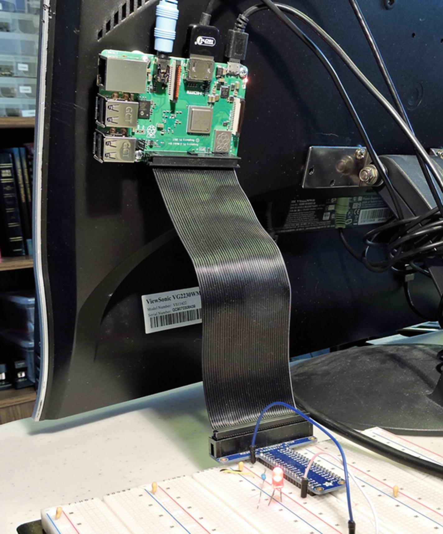
Raspberry Pi 3 B+ using Pi Cobbler to breadboard, with red LED wired to GPIO17 in active high configuration

gpioX/active_low

Sometimes the polarity of a signal is inconvenient. Active low configuration recognizes the fact that the signal is active when the signal is low, rather than the normal high. If this proves inconvenient, you can change the sense of the signal using the active_low pseudo file:
# cat /sys/class/gpio/gpio17/active_low
0
# echo 1 > /sys/class/gpio/gpio17/active_low
# cat /sys/class/gpio/gpio17/active_low
1
The first command (cat) simply reads the current setting. Zero means that normal active high logic is in effect. The second command (echo) changes the active high configuration to active low. The third command confirms the setting was made. Now send a 1 to the gpio17/value pseudo file:
# echo 1 > /sys/class/gpio/gpio17/value
With the active low configuration established, this should cause the LED to go off. If we follow this with a write of zero to the pseudo file, the LED will now go on:
# echo 0 > /sys/class/gpio/gpio17/value

The sense of the logic has been inverted. If you change the wiring of the LED so that it corresponds to Figure 11-4 (B), writing a zero will turn on the LED. In this scenario, the sense of the logic matches the sense of the wiring.

gpioX/edge and gpioX/uevent

Some applications require the detection of changes of a GPIO. Since a user mode program does not receive interrupts, its only option is to continually poll a GPIO for a change in state. This wastes CPU resources and is like kids in the back seat of the car asking, “Are we there yet? Are we there yet?” The driver provides an indirect way for a program to receive a notification of the change.

Acceptable values to be written to this pseudo file are listed in Table 12-2.
Table 12-2

Acceptable Values for Pseudo File Edge

Value

Meaning

none

No edge detection.

rising

Detect a rising signal change.

falling

Detect a falling signal change.

both

Detect a rising or falling signal change.

These values can only be set on an input GPIO and exact case must be used.
# echo in > /sys/class/gpio/gpio17/direction
# echo both > /sys/class/gpio/gpio17/edge
# cat /sys/class/gpio/gpio17/edge
both

Once configured, it is possible to use the uevent pseudo file to check for changes. This must be done using a C/C++ program that can use poll(2) or selectl(2) to get notifications. When using poll(2), request events POLLPRI and POLLERR. When using select(2), the file descriptor should be placed into the exception set. The uevent file is no help to the shell programmer unfortunately.

GPIO Test Script

A simple test script is provided in the directory ~/RPi/scripts/gp and listed in Listing 12-1. To run it on GPIO17, invoke it as follows (from root):
$ sudo -i
# ~pi/RPi/scripts/gp 17
GPIO 17: on
GPIO 17: off  Mon Jul  2 02:48:49 +04 2018
GPIO 17: on
GPIO 17: off  Mon Jul  2 02:48:51 +04 2018
GPIO 17: on
GPIO 17: off  Mon Jul  2 02:48:53 +04 2018
GPIO 17: on
GPIO 17: off  Mon Jul  2 02:48:55 +04 2018
If you had an LED wired up to GPIO17, you should see it blinking slowly.
0001: #!/bin/bash
0002:
0003: GPIO="$1"
0004: SYS=/sys/class/gpio
0005: DEV=/sys/class/gpio/gpio$GPIO
0006:
0007: if [ ! -d $DEV ] ; then
0008:     # Make pin visible
0009:     echo $GPIO >$SYS/export
0010: fi
0011:
0012: # Set pin to output
0013: echo out >$DEV/direction
0014:
0015: function put() {
0016:     # Set value of pin (1 or 0)
0017:     echo $1 >$DEV/value
0018: }
0019:
0020: # Main loop:
0021: while true ; do
0022:     put 1
0023:     echo "GPIO $GPIO: on"
0024:     sleep 1
0025:     put 0
0026:     echo "GPIO $GPIO: off  $(date)"
0027:     sleep 1
0028: done
0029:
0030: # End
Listing 12-1

The ~/RPi/scripts/gp test script

GPIO Input Test

Another simple script is shown in Listing 12-2, which will report the state of an input GPIO as it changes. It requires three arguments:
  1. 1.

    Input GPIO number (defaults to 25)

     
  2. 2.

    Output GPIO number (defaults to 24)

     
  3. 3.

    Active sense: 0=active high, 1=active low (default 0)

     
The following invocation assumes the input GPIO is 25, the LED output is on 17, and the configuration is active high. Press Control-C to exit.
# ~pi/RPi/scripts/input 25 17 0
0000 Status: 0
0001 Status: 1
0002 Status: 0
0003 Status: 1
0004 Status: 0
^C
0001: #!/bin/bash
0002:
0003: INP="${1:-25}"  # Read from GPIO 25 (GEN6)
0004: OUT="${2:-24}"  # Write to GPIO 24 (GEN5)
0005: ALO="${3:-0}"   # 1=active low, else 0
0006:
0007: set -eu
0008: trap "close_all" 0
0009:
0010: function close_all() {
0011:   close $INP
0012:   close $OUT
0013: }
0014: function open() { # pin direction
0015:   dev=$SYS/gpio$1
0016:   if [ ! -d $dev ] ; then
0017:     echo $1 >$SYS/export
0018:   fi
0019:   echo $2 >$dev/direction
0020:   echo none >$dev/edge
0021:   echo $ALO >$dev/active_low
0022: }
0023: function close() { # pin
0024:   echo $1 >$SYS/unexport
0025: }
0026: function put() { # pin value
0027:   echo $2 >$SYS/gpio$1/value
0028: }
0029: function get() { # pin
0030:   read BIT <$SYS/gpio$1/value
0031:   echo $BIT
0032: }
0033:
0034: count=0
0035: SYS=/sys/class/gpio
0036:
0037: open $INP in
0038: open $OUT out
0039: put $OUT 1
0040: LBIT=2
0041:
0042: while true ; do
0043:   RBIT=$(get $INP)
0044:   if [ $RBIT -ne $LBIT ] ; then
0045:     put $OUT $RBIT
0046:     printf "%04d Status: %d\n" $count $RBIT
0047:     LBIT=$RBIT
0048:     let count=count+1
0049:   else
0050:     sleep 1
0051:   fi
0052: done
0053:
0054: # End
Listing 12-2

The ~/RPi/scripts/input script

Summary

This chapter has shown how to apply the sysfs driver interface to GPIO ports. While it may seem that this interface is primarily for use with shell scripts, the uevent pseudo file requires a C/C++ program to take advantage of it. These pseudo files otherwise provide a command-line interface, allowing different GPIO actions.

The next chapter will examine program access to the uevent file and explore direct access to the GPIO registers themselves.