
The 1-Wire protocol was developed by Dallas Semiconductor Corp. initially for the iButton.15 This communication protocol was attractive enough to be applied to other devices and soon adopted by other manufacturers. This chapter provides an overview of the 1-Wire protocol and how it is supported in the Raspberry Pi.
1-Wire Line and Power
Data: The single wire used for data communication
Ground: The ground or “return” wire
The 1-Wire protocol was designed for communication with low-data content devices like temperature sensors. It provides for low-cost remote sensing by supplying power over the same wire used for data communications. Each sensor can accept power from the data line while the data line is in the high state (which is also the line’s idle state). The small amount of power that is siphoned off charges the chip’s internal capacitor (usually about 800 pF).15
When the data line is active (going low), the sensor chips continue to run off of their internal capacitor (in parasitic mode). Data communications cause the data line to fluctuate between low and high. Whenever the line level returns high again, even for a brief instant, the capacitor recharges.
The device also provides an optional VDD pin, allowing power to be supplied to it directly. This is sometimes used when parasitic mode doesn’t work well enough. This, of course, requires an additional wire, adding to the cost. This chapter will focus on the parasitic mode where VDD is connected to the ground.
Line Driving
The data line is driven by open drain transistors in the master and slave devices. The line is held high by a pull-up resistor when the transistors are all in the Off state. To initiate a signal, one transistor turns on and pulls the line down to ground potential.
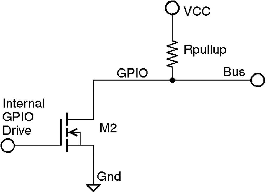
1-Wire driver circuit
Likewise, when a slave is signaled to respond, the master listens to the bus while the slave activates its driving transistor. Whenever all driving transistors are off, the bus returns to the high idle state.
The master can request that all slave devices reset. After the master has made this request, it relinquishes the bus and allows it to return high. All slave devices that are connected to the bus respond by bringing the line low after a short pause. Multiple slaves will bring the line low at the same time, but this is permitted. This informs the master that at least one slave device is attached to the bus. Additionally, this procedure puts all slave devices into a known reset state.
Master and Slave
The master device is always in control of the 1-Wire bus. Slaves speak only to the master when requested. There is never slave-to-slave device communication.
If the master finds that communication becomes difficult for some reason, it may force a bus reset. This corrects for an errant slave device that might be jabbering on the line.
Protocol
This section presents an introduction to the 1-Wire communication protocol. Knowing something about how the signaling works is not only interesting but may be helpful for troubleshooting. More information is available on the Internet.16
Reset
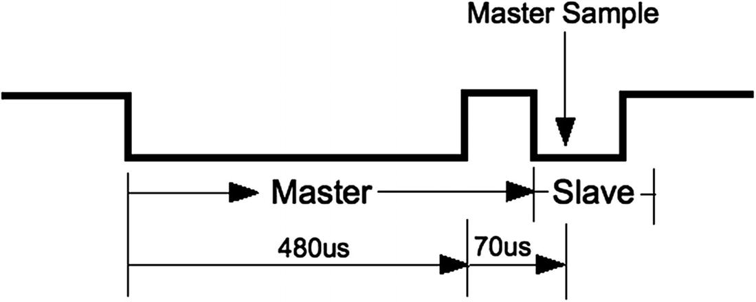
1-Wire reset protocol
For reset, the bus is brought low and held there for approximately 480 μs. Then the bus is released, and the pull-up resistor brings it high again. After a short time, slave devices connected to the bus start responding by bringing the line low and holding it for a time. Several slaves can participate in this at the same time. The master samples the bus at around 70 μs after it releases the bus. If it finds the line low, it knows that there is at least one slave connected and responding.
Soon after the master sampling point, all slaves release the bus again and go into a listening state. They do not respond again until the master specifically addresses a slave device. For simplicity, we’ll omit the discovery protocol used.
Note
Each slave has a guaranteed unique address.
Data I/O
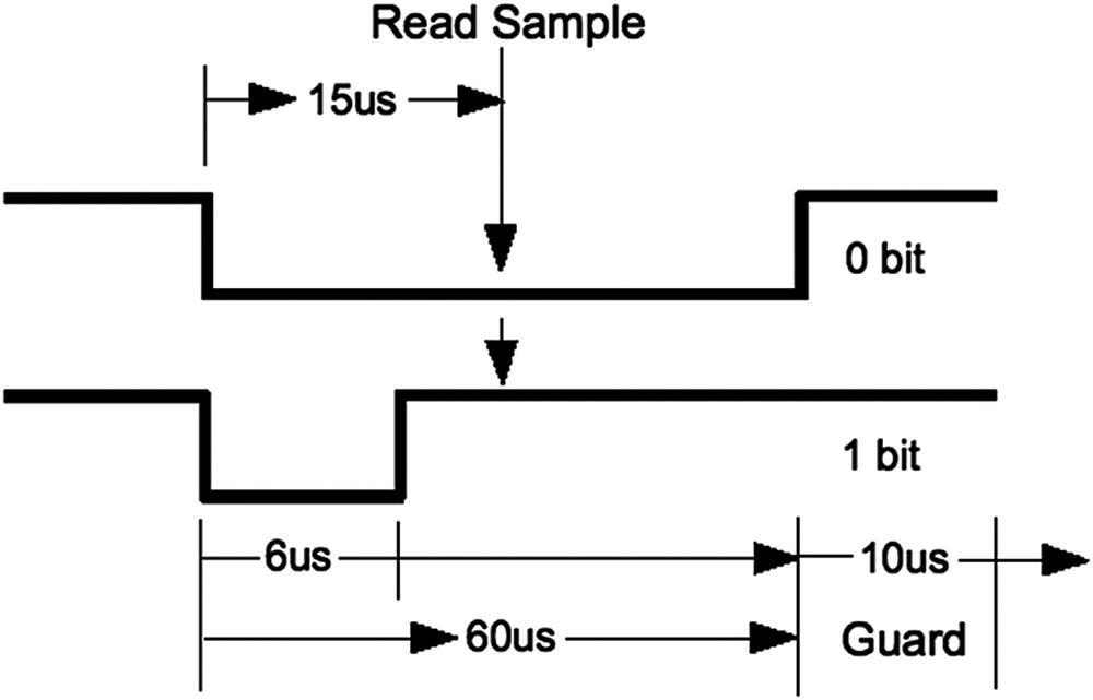
1-Wire read/write of 0 data bit
When a 0 is being transmitted, the line is held low for approximately 60 μs. Then the bus is released and allowed to return high. When a 1 bit is being transmitted, the line is held low for only about 6 μs before releasing the bus. Another data bit is not begun until 70 μs after the start of the previous bit. This leaves a guard time of 10 μs between bits. The receiver then has ample time to process the bit and gain some signal noise immunity.
The receiver notices a data bit is coming when the line drops low. It then starts a timer and samples the bus at approximately 15 μs. If the bus is still in the low state, a 0 data bit is registered. Otherwise, the data bit is interpreted as a 1. Having registered a data bit, the receiver then waits further until the line returns high (in the case of a 0 bit).
The receiver remains idle until it notices the line going low again, announcing the start of the next bit.
The sender can be either the master or the slave, but the master always controls who can speak next. Slaves do not write to the bus unless the master requested it.
Slave Support
1-Wire Slave Driver Support
Device | Module | Description |
|---|---|---|
DS18S20 | w1_therm.c | Precision digital thermometer |
DS18B20 | Programmable resolution thermometer | |
DS1822 | Econo digital thermometer | |
DS28EA00 | 9- to 12-bit digital thermometer with PIO | |
bq27000 | w1_bq27000.c | Highly accurate battery monitor |
DS2408 | w1_ds2408.c | Eight-channel addressable switch |
DS2423 | w1_ds2423.c | 4 KB RAM with counter |
DS2431 | w1_ds2431.c | 1 KB EEPROM |
DS2433 | w1_ds2433.c | 4 KB EEPROM |
DS2760 | w1_ds2760.c | Precision Li+ battery monitor |
DS2780 | w1_ds2780.c | Stand-alone fuel gauge |
Configuration
The parameter gpiopin=4 specifies that the 1-Wire bus is on GPIO4. This used to be hard-coded in the driver but now permits you to choose differently. It is still the default if the parameter is not specified.
Parameter pullup=on is normally required for successful operation. Even though I had attached a 4.7 kohm resistor to +3.3 V for the bus, I could not get my devices to operate in parasitic mode. I recommend that you provide this parameter. Once you have edited the file, reboot for it to take effect.
The referenced README file also contains an entry named w1-gpio-pullup, which you should probably avoid unless you know why you are using it. It will require one additional GPIO to be used to pull up the bus (by default GPIO5).
Reading Temperature
Having not found the pathname /sys/bus/w1, we have confirmation that the device driver is not loaded.
The pseudo file names 28-00000478d75e and 28-0000047931b5 are device entries for the author’s two DS18B20 devices. Don’t worry if you don’t see your entries immediately, since it takes time for the discovery protocol to find them.
Slave Devices
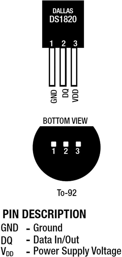
DS18B20 pin-out
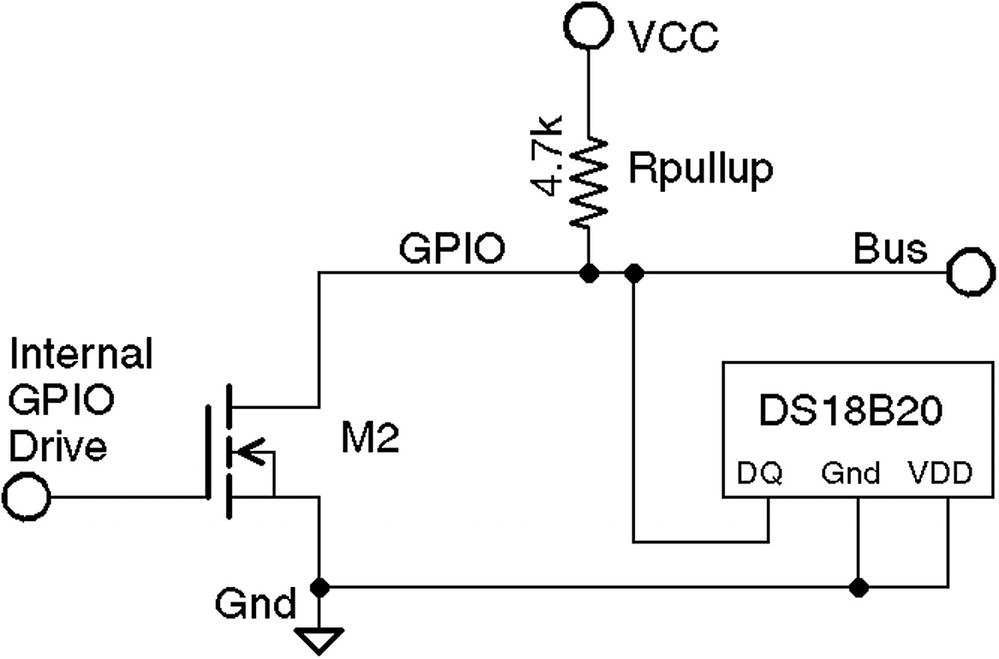
1-Wire with DS18B20 slave circuit, using VCC=3.3 V and 4.7 k pull-up resistor
When things are working correctly, the bus master detects slave devices automatically as part of its periodic scan. When your device(s) are discovered, they will appear in the devices subdirectory with names like 28-0000028f6667.
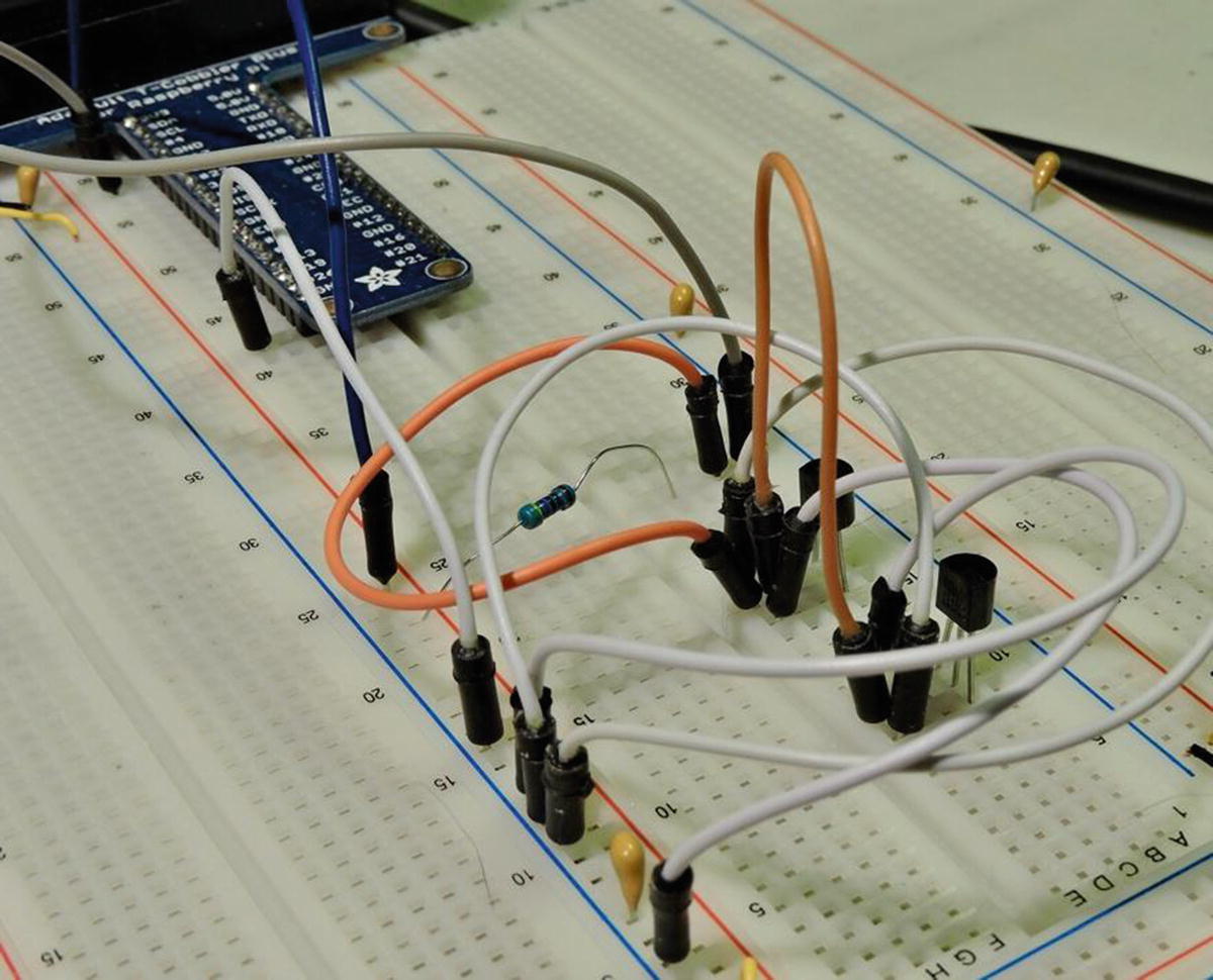
The breadboard with two DS18B20 temperature sensors wired to the Raspberry Pi
Reading the Temperature
The second line ending in t=26375 indicates a reading of 26.375°C.
The value t=85000 is the dead giveaway. If you see this, check your wiring—particularly the pullup resistor. The circuit needs a 4.7 kohm pull-up resistor to +3.3 V.
Summary
In this chapter, the 1-Wire Linux support was put to use to read the Dallas Semiconductor DS18B20 temperature sensor. Table 14-1 lists several other types of 1-wire sensors that you may be able to use. Having driver support makes using sensors like these a breeze.