Table of Contents for
Practical Forensic Imaging
 Practical Forensic Imaging
Published by
No Starch Press, 2016
Practical Forensic Imaging
Published by
No Starch Press, 2016
- Practical Forensic Imaging
- Practical Forensic Imaging
- Practical Forensic Imaging
- Practical Forensic Imaging
- Practical Forensic Imaging
- Practical Forensic Imaging
- Practical Forensic Imaging
- Practical Forensic Imaging
- Practical Forensic Imaging
- Practical Forensic Imaging
- Practical Forensic Imaging
- Practical Forensic Imaging
- Practical Forensic Imaging
- Practical Forensic Imaging
- Practical Forensic Imaging
- Practical Forensic Imaging
- Practical Forensic Imaging
- Practical Forensic Imaging
- Practical Forensic Imaging
- Practical Forensic Imaging
- Practical Forensic Imaging
- Practical Forensic Imaging
- Practical Forensic Imaging
- Practical Forensic Imaging
- Practical Forensic Imaging
5
ATTACHING SUBJECT MEDIA TO AN ACQUISITION HOST
This chapter discusses the physical attachment of subject storage media to an examination host, identification of the subject device on the system, and querying the device firmware for information. You’ll also learn about methods for removing HPA and DCO, unlocking ATA passwords, and decrypting self-encrypting drives. The chapter ends with several special storage topics. Let’s start by examining the subject PC hardware.
Examine Subject PC Hardware
When a PC or notebook is seized in the field or delivered to a forensic lab for examination, more than just the internal disks can be examined. Included in the examination should be a complete review of the PC hardware configuration, BIOS settings, hardware clock, and so on.
NOTE
The scope of this book covers “dead” disk acquisition, that is, drives and PCs that are already powered off. Depending on the organization, a triage process will exist for arriving at a crime or incident scene with live, running machines. This triage process may include taking photographs of screens, using mouse jigglers to prevent password-protected screensavers from activating, or running memory-dumping tools. First responder triage of live PCs is outside the scope of this book.
Physical PC Examination and Disk Removal
Before you unplug any drive cables or unscrew any drives from the drive bays, take photographs of the subject PC to document the hardware configuration, the number of disks it contains, and how the disks are cabled to the mainboard.
Remove disks with care, especially if they’re in old PCs that may not have been opened for many years. The top of each drive can be photographed to capture the serial number and other information on the label. For each disk, note the cable location on the mainboard. If a mainboard has multiple SATA ports, note which port each disk was using.
Open optical drive trays to confirm they don’t contain any discs. Most optical drives have a pinhole that can manually release the drive door without powering on the drive.
Examine the PCI slots for PCI SATA Express drives or PCI NVME drives. If a mainboard has an M.2 or mSATA slot, check for SSD circuit boards.
Subject PC Hardware Review
After removing all the drives from the subject PC enclosure, power on the subject mainboard and note the BIOS configuration, clock, boot order, potential BIOS logs, version, and so forth.
If you require further information about the subject PC, examine it using a forensic boot CD that contains various hardware analysis tools, such as lshw, dmidecode, biosdecode, lspic, and more.
You might be able to retrieve some vendor-specific information by using vendor-specific tools—for example, vpddecode for IBM and Lenovo hardware or ownership for Compaq hardware ownership tags.
Examine and document any additional hardware components as well, such as memory modules or PCI cards.
Attach Subject Disk to an Acquisition Host
After physically attaching the subject drive to the examiner workstation (using a write-blocking mechanism), you need to identify the correct block device associated with the subject drive. To reliably identify the subject drive on the acquisition host, list the storage media devices, confirm any unique identifiers associated with the physical drive, and determine the corresponding device file in /dev. This section examines these steps in more detail.
View Acquisition Host Hardware
Understanding the examination host’s hardware configuration is useful for performance tuning, capacity planning, maintaining a stable platform, troubleshooting, isolating faults, and reducing the risk of human error. In this section, you’ll see examples of tools you can use for listing and viewing PC hardware.
Using the lshw tool, you can generate a quick overview of the examiner workstation hardware:
# lshw -businfo
The bus information describes the device specific addresses, such as pci@domain:bus:slot.function, scsi@host.channel.target.lun, and usb@bus:device.
You can also use lshw to specifically look for an attached device type. For example:
# lshw -businfo -class storage
Bus info Device Class Description
=======================================================
...
usb@2:5.2 scsi22 storage Forensic SATA/IDE Bridge
...
# lshw -businfo -class disk
Bus info Device Class Description
=======================================================
...
scsi@22:0.0.0 /dev/sdp disk 120GB SSD 850
...
Note that scsi22 links to scsi@22:.0.0.0, which links to /dev/sdp. Identifying the Linux device file for an attached physical drive is discussed further in the following sections.
If the subject drive has been externally attached, it’s likely connected via USB, Thunderbolt, FireWire, or eSATA (and in rare cases, possibly Fibre Channel).
If the drive has been internally attached, it’s likely connected via SATA cable, a PCI Express slot, an M.2 interface, or SAS cable (or possibly legacy interfaces, such as parallel SCSI or IDE).
You can list the devices attached to the PCI bus (including parallel PCI and PCI Express) using the lspci tool:
# lspci
The PCI bus categorizes devices by class (see http://pci-ids.ucw.cz/ for more information about PCI IDs and device classes). Devices matching the Mass storage controller class (class ID 01) are of interest because they manage attached storage media.
Newer versions of lspci (as of pciutils version 3.30) can list the PCI bus by device class, which can be useful to isolate specific hardware of interest. The following command lists all SATA mass storage controller (class ID 01, subclass ID 06) devices:
# lspci -d ::0106
This command enumerates all the SCSI, IDE, RAID, ATA, SATA, SAS, and NVME mass storage controller devices on a system:
# for i in 00 01 04 05 06 07 08; do lspci -d ::01$i; done
Another PCI class that can manage connected storage media is the serial bus controller class (class ID 0C). The following command lists all devices with the USB serial bus controller class (class ID 0C, subclass ID 03):
# lspci -d ::0C03
This command enumerates all FireWire, USB, and Fibre Channel serial bus controllers on the examiner host:
# for i in 00 03 04; do lspci -d ::0C$i; done
If the subject drive is attached via USB, it won’t appear on the PCI bus. You can list USB devices separately using lsusb. Without options, the command generates a list of all attached USB devices:
# lsusb
...
Bus 001 Device 005: ID 0951:1665 Kingston Technology
Bus 001 Device 002: ID 8087:0024 Intel Corp. Integrated Rate Matching Hub
Bus 001 Device 001: ID 1d6b:0002 Linux Foundation 2.0 root hub
Here a USB thumb drive is attached to USB bus 1 and assigned a USB device ID of 5. Running lsusb -v will provide more detailed output about the USB device.1
The preceding tools and examples provide an overview of the storage media controllers and the hardware attached to an examiner workstation. The lshw(1), lspci(8), and lsusb(8) manual pages explain additional parameters and features, which you can use to view more detail about the hardware.
Identify the Subject Drive
Having an understanding of the examiner workstation hardware, especially the available bus systems and controllers, will help you locate where a subject disk is attached. The next step is to positively confirm the identity of the subject drive using some distinct information, such as a serial number, unique model number, or other unique property.
You can use multiple approaches to identify the subject device. If the subject disk is attached via the USB bus and listed with the lsusb tool, you can retrieve more information by specifying the subject disk’s vendor:productID, as shown here:
# lsusb -vd 0781:5583
Bus 004 Device 002: ID 0781:5583 SanDisk Corp.
...
idVendor 0x0781 SanDisk Corp.
idProduct 0x5583
bcdDevice 1.00
iManufacturer 1 SanDisk
iProduct 2 Ultra Fit
iSerial 3 4C530001200627113025
...
wSpeedsSupported 0x000e
Device can operate at Full Speed (12Mbps)
Device can operate at High Speed (480Mbps)
Device can operate at SuperSpeed (5Gbps)
...
From this output, you can use the unique information (serial number and so on) about the device to confirm the identity of the attached device as the subject drive. If the serial number or other unique properties match the physically attached drive, you’ve identified the correct device.
Nearly all drives are accessible via SCSI commands (directly attached NVME drives are a notable exception). To query for an attached storage device, you can use the lsscsi tool. It supports a number of transport layer protocols, including SATA, USB, SAS, FireWire, ATA, SCSI, Fibre Channel, and more. lsscsi is also useful for linking kernel device paths with device files in /dev:
# lsscsi -v
...
[6:0:0:0] disk ATA INTEL SSDSA2CW30 0302 /dev/sda
dir: /sys/bus/scsi/devices/6:0:0:0 [/sys/devices/pci0000:00/0000:00:1f.2/ata7/
host6/target6:0:0/6:0:0:0]
...
The kernel outputs an informational message when devices are attached or detached from a host system. This is the kernel ring buffer and is viewed with the dmesg tool. Running dmesg with the -T flag prints human-readable timestamps, which are useful when you’re determining which device was added at a known time:
# dmesg -T
...
[Sun May 15 13:44:45 2016] usb 2-1: new SuperSpeed USB device number 9 using
xhci_hcd
[Sun May 15 13:44:45 2016] usb 2-1: New USB device found, idVendor=0781,
idProduct=5583
[Sun May 15 13:44:45 2016] usb 2-1: New USB device strings: Mfr=1, Product=2,
SerialNumber=3
[Sun May 15 13:44:45 2016] usb 2-1: Product: Ultra Fit
[Sun May 15 13:44:45 2016] usb 2-1: Manufacturer: SanDisk
[Sun May 15 13:44:45 2016] usb 2-1: SerialNumber: 4C530001141203113173
[Sun May 15 13:44:45 2016] usb-storage 2-1:1.0: USB Mass Storage device detected
[Sun May 15 13:44:45 2016] scsi host24: usb-storage 2-1:1.0
[Sun May 15 13:44:46 2016] scsi 24:0:0:0: Direct-Access SanDisk Ultra Fit
1.00 PQ: 0 ANSI: 6
[Sun May 15 13:44:46 2016] sd 24:0:0:0: Attached scsi generic sg5 type 0
[Sun May 15 13:44:46 2016] sd 24:0:0:0: [sdf] 30375936 512-byte logical blocks:
(15.6 GB/14.5 GiB)
[Sun May 15 13:44:46 2016] sd 24:0:0:0: [sdf] Write Protect is off
[Sun May 15 13:44:46 2016] sd 24:0:0:0: [sdf] Mode Sense: 43 00 00 00
[Sun May 15 13:44:46 2016] sd 24:0:0:0: [sdf] Write cache: disabled, read cache:
enabled, doesn't support DPO or FUA
[Sun May 15 13:44:46 2016] sdf: sdf1
[Sun May 15 13:44:46 2016] sd 24:0:0:0: [sdf] Attached SCSI removable disk
You can use this output to identify an attached physical device, linking the USB device to a SCSI host ID and a block device name. In this example, usb 2-1: refers to bus 2 and physical port 1 (the plug). The USB drive is assigned device number 9 and uses the xhci_hcd driver (which has USB3 support). The vendor and product ID strings, idVendor=0781, idProduct=5583, are displayed, followed by informational strings for the manufacturer, product, and serial number (these can be different from idVendor and idProduct). The Bulk-Only Transport usb-storage driver detects the device (not needed for UASP devices), and scsi host24: indicates a SCSI host number has been assigned to the device and corresponds to the SCSI address 24:0:0:0:. Two devices are created, sg5 (generic SCSI) and sdf (block device), which correspond to /dev/sg5 and /dev/sdf. Some information about the (now established) SCSI device is queried, and partition tables are detected (sdf1).
A simpler command to list all attached storage devices, including descriptive information and device paths, is the lsblk command. Newer versions of lsblk provide output options for vendor, model, revision, serial number, and WWN (World Wide Name; https://en.wikipedia.org/wiki/World_Wide_Name) number. In addition, lsblk provides useful technical details, such as the device name, size, physical and logical sector size, transport (USB, SATA, SAS, and so on), SCSI address, and more:
# lsblk -pd -o TRAN,NAME,SERIAL,VENDOR,MODEL,REV,WWN,SIZE,HCTL,SUBSYSTEMS,HCTL
Most of the tools demonstrated here are simply reading different files and directories from the Linux /proc directory. You’ll find more information about attached drives and other kernel structures in the /proc tree. Consult the proc(5) manual page for more information about the proc filesystem.
Query the Subject Disk for Information
After attaching the subject drive to the examiner workstation and positively identifying the correct Linux device to work with, you can gather additional meta information about the device. You can query the device directly for information about the drive, the firmware, SMART data, and other configuration details.
A number of tools are available to query information stored in the hard drive. Typically, you access this firmware information using lower-level ATA or SCSI interface commands, which interact directly with the drive electronics.
Document Device Identification Details
At this point, you should have a number of details and technical identifiers about the drive attached to the examiner host, including the following:
• Vendor, make, and model
• Serial number or WWN
• Linux device name
• PCI domain:bus:slot.function
• PCI vendorID:deviceID
• USB bus:device
• USB vendorID:productID
• SCSI host:channel:target:lun
You can save this information for reporting purposes by redirecting the various tool command outputs to text files.
Document evidence for the use of a write blocker. If you’re using a hardware write blocker, such as Tableau, query it and save the results:
# tableau-parm /dev/sdc > write-blocked.txt
Here /dev/sdc should be replaced with the relevant device of the subject drive.
If you’re using a software write blocker, such as wrtblk, query blockdev for a report on the current status of the device (including the read-only flag):
# blockdev --report /dev/sda > wrtblk.txt
Here /dev/sda should be replaced with the relevant device of the subject drive.
If the subject drive is attached via USB, you can specify it either by the bus:device (using -s) or by vendor:product (using -d). The following two commands will produce and save the same verbose output:
# lsusb -v -s 2:2 > lsusb.txt
# lsusb -v -d 13fe:5200 > lsusb.txt
Here 2:2 and 13fe:5200 should be replaced with the relevant values for the subject drive on your acquisition host.
The lsblk command can specify a Linux device, and the -O flag will output all available columns in the output:
# lsblk -O /dev/sda > lsblk.txt
Here /dev/sda should be replaced with the relevant device of the subject drive on your acquisition host.
The lsscsi command can also save a certain perspective of the attached drive, specifying the SCSI address to use:
# lsscsi -vtg -L 16:0:0:0 > lsscsi.txt
Here 16:0:0:0 should be replaced with the relevant SCSI address of the subject drive on your acquisition host.
Relevant dmesg output could also be copied into a text file if desired.
The examples shown in this section illustrated how to save command output for a specific subject drive. For brevity, subsequent chapters sometimes will not include examples of saving data to files, focusing instead on the construction of commands.
Query Disk Capabilities and Features with hdparm
Many of the tools discussed previously (lsusb, lspci, lsblk, and so on) have queried the Linux system and kernel structures for information. However, it’s possible to query a drive directly for additional information. The hdparm tool is useful for sending commands to most drives attached to a Linux system.
The hdparm tool operates by sending requests to the OS disk drivers (using ioctls) to retrieve information about the disk. From a forensics perspective, a number of items may be of interest or useful to document:
• Details about the drive geometry (physical and logical)
• The disk’s supported standards, features, and capabilities
• States and flags related to the drive configuration
• DCO and HPA information
• Security information
• Vendor information, such as make, model, and serial number
• The WWN device identifier (if it exists)
• Time needed for secure erase (for most disks, this is roughly the acquisition time)
For more detailed information about hdparm’s features, see the hdparm(8) manual page.
The following example shows how to use hdparm to get an overview of the disk using the -I flag together with the raw disk device. The listing is annotated with comments relevant to forensic investigators.
The output begins with documenting information about the drive, including manufacturer, model, serial number, and the standards with which it is compliant. Also in the output are various drive parameters, such as physical and logical sector size, number of sectors, form factor, and other physical properties.
# hdparm -I /dev/sda
/dev/sda:
ATA device, with non-removable media
Model Number: WDC WD20EZRX-00D8PB0
Serial Number: WD-WCC4NDA2N98P
Firmware Revision: 80.00A80
Transport: Serial, SATA 1.0a, SATA II Extensions, SATA Rev 2.5,
SATA Rev 2.6, SATA Rev 3.0
Standards:
Supported: 9 8 7 6 5
Likely used: 9
Configuration:
Logical max current
cylinders 16383 16383
heads 16 16
sectors/track 63 63
--
CHS current addressable sectors: 16514064
LBA user addressable sectors: 268435455
LBA48 user addressable sectors: 3907029168
Logical Sector size: 512 bytes
Physical Sector size: 4096 bytes
device size with M = 1024*1024: 1907729 MBytes
device size with M = 1000*1000: 2000398 MBytes (2000 GB)
cache/buffer size = unknown
Nominal Media Rotation Rate: 5400
Capabilities:
LBA, IORDY(can be disabled)
Queue depth: 32
Standby timer values: spec'd by Standard, with device specific minimum
R/W multiple sector transfer: Max = 16 Current = 16
DMA: mdma0 mdma1 mdma2 udma0 udma1 udma2 udma3 udma4 udma5 *udma6
Cycle time: min=120ns recommended=120ns
PIO: pio0 pio1 pio2 pio3 pio4
Cycle time: no flow control=120ns IORDY flow control=120ns
...
The next section of the output describes the features available on a drive, and the star (*) indicates if a feature is currently enabled. (To understand vendor-specific features, you might need additional proprietary documentation.) This is useful when you’re preparing for a forensic acquisition, because it indicates the status of security feature sets and other things like the DCO (Device Configuration Overlay feature set).
...
Commands/features:
Enabled Supported:
* SMART feature set
Security Mode feature set
* Power Management feature set
* Write cache
* Look-ahead
* Host Protected Area feature set
* WRITE_BUFFER command
* READ_BUFFER command
* NOP cmd
* DOWNLOAD_MICROCODE
Power-Up In Standby feature set
* SET_FEATURES required to spinup after power up
SET_MAX security extension
* 48-bit Address feature set
* Device Configuration Overlay feature set
* Mandatory FLUSH_CACHE
* FLUSH_CACHE_EXT
* SMART error logging
* SMART self-test
* General Purpose Logging feature set
* 64-bit World wide name
* WRITE_UNCORRECTABLE_EXT command
* {READ,WRITE}_DMA_EXT_GPL commands
* Segmented DOWNLOAD_MICROCODE
* Gen1 signaling speed (1.5Gb/s)
* Gen2 signaling speed (3.0Gb/s)
* Gen3 signaling speed (6.0Gb/s)
* Native Command Queueing (NCQ)
* Host-initiated interface power management
* Phy event counters
* NCQ priority information
* READ_LOG_DMA_EXT equivalent to READ_LOG_EXT
* DMA Setup Auto-Activate optimization
Device-initiated interface power management
* Software settings preservation
* SMART Command Transport (SCT) feature set
* SCT Write Same (AC2)
* SCT Features Control (AC4)
* SCT Data Tables (AC5)
unknown 206[12] (vendor specific)
unknown 206[13] (vendor specific)
unknown 206[14] (vendor specific)
...
The next section of the hdparm output provides more detail about the currently active security features, which are important when you’re determining if a drive is locked or encrypted. The time needed for a secure erase is also a rough estimate of how long an acquisition might take (if the subject drive is the performance bottleneck).
...
Security:
Master password revision code = 65534
supported
not enabled
not locked
not frozen
not expired: security count
supported: enhanced erase
324min for SECURITY ERASE UNIT. 324min for ENHANCED SECURITY ERASE UNIT.
...
The final section of the hdparm output displays the WWN again, but this time it’s broken down into the NAA (which describes the rest of the WWN), the IEEE OUI assigned vendor ID, and the rest of the WWN (which isunique to the drive).
...
Logical Unit WWN Device Identifier: 50014ee25fcfe40c
NAA : 5
IEEE OUI : 0014ee
Unique ID : 25fcfe40c
Checksum: correct
The hdparm output contains a number of items of interest to forensic investigators, either for documentation or as information for further analysis. To include the entire output of hdparm -I in a forensic report, you can redirect it to a text file.
A similar tool for querying SCSI drives is sdparm, which you can use to access SCSI mode pages. Running sdparm with the flags -a -l retrieves a verbose list of disk parameters. A more concise query using sdparm -i can extract the Vital Product Data (VPD), which provides unique identifying information about the make, model, and serial number of SCSI and SAS drives.
Extract SMART Data with smartctl
SMART was developed in the early 1990s to help monitor hard disks and predict failures. It was added to the SCSI-3 standard in 1995(SCSI-3 standard: X3T10/94-190 Rev 4) and the ATA-3 standard in 1997 (ATA-3 standard: X3.298-1997). Because certain details about the disk hardware may be of value in forensic investigations, in this section, you’ll learn several techniques to extract SMART information about the disk hardware.
The smartctl command is part of the smartmontools package and provides access to the SMART interface built into nearly all modern hard drives. The smartctl command queries attached ATA, SATA, SAS, and SCSI hardware.
SMART provides a number of variables and statistics about a disk, some of which could be of interest to a forensic investigator. For example:
• Statistics about errors on the disk and the overall health of the disk
• Number of times the disk was powered on
• Number of hours the disk was in operation
• Number of bytes read and written (often expressed in gigabytes)
• Various SMART logs (temperature history, and so on)2
The following example shows SMART data requested from a drive. The listing is annotated with comments relevant to forensic investigators.
The -x flag instructs smartctl to print all available information. The first block of output is the information section, which provides unique identifying information about the drive. You can also retrieve most of this information using other tools, such as hdparm, as shown in previous examples.
# smartctl -x /dev/sda
smartctl 6.4 2014-10-07 r4002 [x86_64-linux-4.2.0-22-generic] (local build)
Copyright (C) 2002-14, Bruce Allen, Christian Franke, www.smartmontools.org
=== START OF INFORMATION SECTION ===
Model Family: Western Digital Green
Device Model: WDC WD20EZRX-00D8PB0
Serial Number: WD-WCC4NDA2N98P
LU WWN Device Id: 5 0014ee 25fcfe40c
Firmware Version: 80.00A80
User Capacity: 2,000,398,934,016 bytes [2.00 TB]
Sector Sizes: 512 bytes logical, 4096 bytes physical
Rotation Rate: 5400 rpm
Device is: In smartctl database [for details use: -P show]
ATA Version is: ACS-2 (minor revision not indicated)
SATA Version is: SATA 3.0, 6.0 Gb/s (current: 6.0 Gb/s)
Local Time is: Thu Jan 7 12:33:43 2016 CET
SMART support is: Available - device has SMART capability.
SMART support is: Enabled
AAM feature is: Unavailable
APM feature is: Unavailable
Rd look-ahead is: Enabled
Write cache is: Enabled
ATA Security is: Disabled, NOT FROZEN [SEC1]
Wt Cache Reorder: Enabled
...
The following SMART data section shows the health of the drive and the results of self-tests. An unhealthy drive is an early warning of possible acquisition issues. Additional SMART capabilities are then listed.
...
=== START OF READ SMART DATA SECTION ===
SMART overall-health self-assessment test result: PASSED
General SMART Values:
Offline data collection status: (0x82) Offline data collection activity
was completed without error.
Auto Offline Data Collection: Enabled.
Self-test execution status: ( 0) The previous self-test routine completed
without error or no self-test has ever
been run.
Total time to complete Offline
data collection: (30480) seconds.
Offline data collection
capabilities: (0x7b) SMART execute Offline immediate.
Auto Offline data collection on/off support.
Suspend Offline collection upon new
command.
Offline surface scan supported.
Self-test supported.
Conveyance Self-test supported.
Selective Self-test supported.
SMART capabilities: (0x0003) Saves SMART data before entering
power-saving mode.
Supports SMART auto save timer.
Error logging capability: (0x01) Error logging supported.
General Purpose Logging supported.
Short self-test routine
recommended polling time: ( 2) minutes.
Extended self-test routine
recommended polling time: ( 307) minutes.
Conveyance self-test routine
recommended polling time: ( 5) minutes.
SCT capabilities: (0x7035) SCT Status supported.
SCT Feature Control supported.
SCT Data Table supported.
...
The next section provides more statistics about the drive. Of possible forensic interest here are statistics on the history of the drive usage; for example, the cumulative number of hours the drive has been powered on (Power_On_Hours) and how many times the drive has been powered up (Power_Cycle_Count). Both attributes may correlate with the PC from where they were taken. The total logical block addresses (LBAs) read and written indicates the drive volume usage in the past.
...
SMART Attributes Data Structure revision number: 16
Vendor Specific SMART Attributes with Thresholds:
ID# ATTRIBUTE_NAME FLAGS VALUE WORST THRESH FAIL RAW_VALUE
1 Raw_Read_Error_Rate POSR-K 200 200 051 - 0
3 Spin_Up_Time POS--K 181 180 021 - 5908
4 Start_Stop_Count -O--CK 100 100 000 - 61
5 Reallocated_Sector_Ct PO--CK 200 200 140 - 0
7 Seek_Error_Rate -OSR-K 200 200 000 - 0
9 Power_On_Hours -O--CK 099 099 000 - 989
10 Spin_Retry_Count -O--CK 100 253 000 - 0
11 Calibration_Retry_Count -O--CK 100 253 000 - 0
12 Power_Cycle_Count -O--CK 100 100 000 - 59
192 Power-Off_Retract_Count -O--CK 200 200 000 - 33
193 Load_Cycle_Count -O--CK 199 199 000 - 3721
194 Temperature_Celsius -O---K 119 110 000 - 31
196 Reallocated_Event_Count -O--CK 200 200 000 - 0
197 Current_Pending_Sector -O--CK 200 200 000 - 4
198 Offline_Uncorrectable ----CK 200 200 000 - 4
199 UDMA_CRC_Error_Count -O--CK 200 200 000 - 0
200 Multi_Zone_Error_Rate ---R-- 200 200 000 - 4
||||||_ K auto-keep
|||||__ C event count
||||___ R error rate
|||____ S speed/performance
||_____ O updated online
|______ P prefailure warning
...
The next section is the log directory, which describes the SMART logs available on the drive. The logs are included in the smartctl -x output with repeating entries removed (“skipped”). Some of these logs may be of interest in a forensic investigation.
...
General Purpose Log Directory Version 1
SMART Log Directory Version 1 [multi-sector log support]
Address Access R/W Size Description
0x00 GPL,SL R/O 1 Log Directory
0x01 SL R/O 1 Summary SMART error log
0x02 SL R/O 5 Comprehensive SMART error log
0x03 GPL R/O 6 Ext. Comprehensive SMART error log
0x06 SL R/O 1 SMART self-test log
0x07 GPL R/O 1 Extended self-test log
0x09 SL R/W 1 Selective self-test log
0x10 GPL R/O 1 SATA NCQ Queued Error log
0x11 GPL R/O 1 SATA Phy Event Counters log
0x80-0x9f GPL,SL R/W 16 Host vendor specific log
0xa0-0xa7 GPL,SL VS 16 Device vendor specific log
0xa8-0xb7 GPL,SL VS 1 Device vendor specific log
0xbd GPL,SL VS 1 Device vendor specific log
0xc0 GPL,SL VS 1 Device vendor specific log
0xc1 GPL VS 93 Device vendor specific log
0xe0 GPL,SL R/W 1 SCT Command/Status
0xe1 GPL,SL R/W 1 SCT Data Transfer
...
The next section of log information displays the results of self-tests. Failed self-tests are an early warning that the acquisition could have issues.
...
SMART Extended Comprehensive Error Log Version: 1 (6 sectors)
No Errors Logged
SMART Extended Self-test Log Version: 1 (1 sectors)
Num Test_Description Status Remaining LifeTime(hours) LBA_of...
# 1 Short offline Completed without error 00% 0 -
SMART Selective self-test log data structure revision number 1
SPAN MIN_LBA MAX_LBA CURRENT_TEST_STATUS
1 0 0 Not_testing
2 0 0 Not_testing
3 0 0 Not_testing
4 0 0 Not_testing
5 0 0 Not_testing
Selective self-test flags (0x0):
After scanning selected spans, do NOT read-scan remainder of disk.
If Selective self-test is pending on power-up, resume after 0 minute delay.
SCT Status Version: 3
SCT Version (vendor specific): 258 (0x0102)
SCT Support Level: 1
Device State: Active (0)
...
The next output block describes a drive’s temperature statistics. This information could be useful to monitor during the acquisition process. For investigation purposes, the minimum and maximum temperatures reached during the drive’s lifetime might be of interest if correlated with environ-mental factors linked to a suspect’s PC. Vendor-specific SMART data is not part of the generic SMART standard, and you may need additional proprietary documentation to understand it.
...
Current Temperature: 31 Celsius
Power Cycle Min/Max Temperature: 22/31 Celsius
Lifetime Min/Max Temperature: 20/41 Celsius
Under/Over Temperature Limit Count: 0/0
Vendor specific:
01 00 00 00 00 00 00 00 00 00 00 00 00 00 00 00
00 00 00 00 00 00 00 00 00 00 00 00 00 00 00 00
...
Some SMART-capable drives maintain a log of temperature history. You can calculate the history from the interval multiplied by the history size. In this example, 478 minutes are roughly 8 hours of temperature data. Some disks have a temperature-logging interval set much higher (one hour or more). The temperature-logging interval is potentially useful for investigations: if a disk were seized immediately after a crime, known temperature variations might be correlated with the disk temperature record.
...
SCT Temperature History Version: 2
Temperature Sampling Period: 1 minute
Temperature Logging Interval: 1 minute
Min/Max recommended Temperature: 0/60 Celsius
Min/Max Temperature Limit: -41/85 Celsius
Temperature History Size (Index): 478 (175)
Index Estimated Time Temperature Celsius
176 2016-01-07 05:00 ? -
... ..(300 skipped). .. -
477 2016-01-07 10:01 ? -
0 2016-01-07 10:02 29 **********
1 2016-01-07 10:03 30 ***********
... ..( 68 skipped). .. ***********
70 2016-01-07 11:12 30 ***********
71 2016-01-07 11:13 31 ************
... ..(103 skipped). .. ************
175 2016-01-07 12:57 31 ************
...
The final section of output in this example shows statistics of physical errors. It can be useful to compare these statistics with values during or at the end of an acquisition to ensure no physical errors arose during the process.
...
SCT Error Recovery Control command not supported
Device Statistics (GP/SMART Log 0x04) not supported
SATA Phy Event Counters (GP Log 0x11)
ID Size Value Description
0x0001 2 0 Command failed due to ICRC error
0x0002 2 0 R_ERR response for data FIS
0x0003 2 0 R_ERR response for device-to-host data FIS
0x0004 2 0 R_ERR response for host-to-device data FIS
0x0005 2 0 R_ERR response for non-data FIS
0x0006 2 0 R_ERR response for device-to-host non-data FIS
0x0007 2 0 R_ERR response for host-to-device non-data FIS
0x0008 2 0 Device-to-host non-data FIS retries
0x0009 2 6 Transition from drive PhyRdy to drive PhyNRdy
0x000a 2 6 Device-to-host register FISes sent due to a COMRESET
0x000b 2 0 CRC errors within host-to-device FIS
0x000f 2 0 R_ERR response for host-to-device data FIS, CRC
0x0012 2 0 R_ERR response for host-to-device non-data FIS, CRC
0x8000 4 14532 Vendor specific
Other SMART logs might exist depending on the drive vendor. Consult the smartctl(8) manual page for more information about additional flags and queries that you can send to attached subject drives.
Enable Access to Hidden Sectors
Forensic literature often includes handling the HPA and DCO as part of the imaging process. Indeed, some imaging software has the capability to detect and remove these hidden areas at acquisition time. This book positions the detection and removal of the HPA/DCO as part of the preparation process, not the actual imaging. There is no special technique to image these hidden areas once they’ve been made accessible. They’re simply disk sectors protected by drive configuration parameters. It is a simple preparatory step to make them available for a subsequent imaging process. Removing the HPA or DCO modifies the drive’s configuration, but it does not modify its contents.3
This section also covers drive maintenance sectors and service areas on a disk, but this topic is mentioned only briefly, because these areas are not easily accessible using common open source tools.
Remove a DCO
The DCO was developed to allow PC system manufacturers to make different drive models appear to have the same features. Using a DCO, certain features can be disabled, and the capacity of a drive (number of usable sectors) can be reduced to fit a vendor’s requirements. Identifying and removing the DCO is standard forensic practice when you’re analyzing a suspect drive.
The DCO is a general configuration overlay, and multiple features can be overridden. It does not only refer to the number of sectors on a drive.
Two hdparm commands can determine if a DCO exists and provide the number of real sectors available. The first command determines if the drive has the DCO feature set enabled. In this example, the current size of the disk is reported to be 474GB or 926773168 sectors (512-byte sector size) and the asterisk (*) next to Device Configuration Overlay feature set indicates it is active:
# hdparm -I /dev/sdl
/dev/sdl:
ATA device, with non-removable media
Model Number: WDC WD5003AZEX-00MK2A0
...
LBA48 user addressable sectors: 926773168
Logical Sector size: 512 bytes
Physical Sector size: 4096 bytes
device size with M = 1024*1024: 452525 MBytes
device size with M = 1000*1000: 474507 MBytes (474 GB)
...
* Device Configuration Overlay feature set
...
The second command specifically queries for the features modified by a DCO:
# hdparm --dco-identify /dev/sdl
/dev/sdl:
DCO Revision: 0x0002
The following features can be selectively disabled via DCO:
Transfer modes:
udma0 udma1 udma2 udma3 udma4 udma5 udma6
Real max sectors: 976773168
ATA command/feature sets:
security HPA
SATA command/feature sets:
NCQ interface_power_management SSP
In this example, “Real max sectors” is 976773168, which is 25GB less than the reported size, indicating the existence of a DCO. The reported size of 474GB is also a mismatch to the 500GB label on the physical drive. You can confirm the expected number of sectors by checking the drive model number with the vendor’s product documentation.
Having confirmed the existence of a DCO using hdparm, you can use the same command to remove it. First, run hdparm to ensure the drive configuration is not locked or frozen:
# hdparm -I /dev/sdl
/dev/sdl:
ATA device, with non-removable media
Model Number: WDC WD5003AZEX-00MK2A0
...
Security:
...
not locked
not frozen
...
Some BIOSes or OSes will issue an ATA command to freeze the DCO configuration during boot to prevent malicious changes. In this case, hot plugging the drive power cable after booting should cause the drive to spin up in an unfrozen state.4 Many USB bridges automatically spin up an attached disk in an unfrozen state. If the drive is locked, refer to “Identify and Unlock ATA Password-Protected Disks” on page 126.
Once the drive is ready, you can send the appropriate ATA command to reset the DCO, making the additional hidden sectors available.
Simply running the hdparm command with the --dco-restore option will do nothing but generate a warning message:
# hdparm --dco-restore /dev/sdl
/dev/sdl:
Use of --dco-restore is VERY DANGEROUS.
You are trying to deliberately reset your drive configuration back to the factory
defaults.
This may change the apparent capacity and feature set of the drive, making all data
on it inaccessible.
You could lose *everything*.
Please supply the --yes-i-know-what-i-am-doing flag if you really want this.
Program aborted.
Following the instructions, and including the --yes-i-know-what-i-am-doing flag, you can remove the DCO as follows:
# hdparm --yes-i-know-what-i-am-doing --dco-restore /dev/sdl
/dev/sdl:
issuing DCO restore command
Now when you run the hdparm -I command again, the full sectors will be revealed.
# hdparm -I /dev/sdl
/dev/sdl:
ATA device, with non-removable media
Model Number: WDC WD5003AZEX-00MK2A0
...
LBA48 user addressable sectors: 976773168
Logical Sector size: 512 bytes
Physical Sector size: 4096 bytes
device size with M = 1024*1024: 476940 MBytes
device size with M = 1000*1000: 500107 MBytes (500 GB)
...
Now you can acquire the drive or analyze it with forensic tools. It’s important to note the DCO hidden area’s exact sector offset, which will be useful when you want to extract only the DCO sectors for separate analysis.
Removing the DCO using hdparm can be tricky. Read the hdparm(8) manual page if a particular drive is causing problems with the removal commands.
The tableau-parm tool has an -r flag that should remove the DCO (and possibly the HPA) from the drive.
Remove an HPA
The HPA was developed to allow PC system manufacturers to store data in a way that is normally inaccessible to a customer. Examples of HPA uses include diagnostic tools, recovery partitions, and so on. These special areas are often activated with BIOS hotkeys during startup.
You can detect the existence of an HPA using a single hdparm command:
# hdparm -N /dev/sdl
/dev/sdl:
max sectors = 879095852/976773168, HPA is enabled
Here HPA is enabled indicates that an HPA exists. The max sectors provides the visible sector count followed by the real sector count. In this example, subtracting the two sector counts reveals a 50GB difference, which is the host protected area.
You can temporarily remove the HPA using the same command (as with the DCO removal, a warning message appears, and you need to use the --yes-i-know-what-i-am-doing flag):
# hdparm --yes-i-know-what-i-am-doing -N 976773168 /dev/sdl
/dev/sdl:
setting max visible sectors to 976773168 (temporary)
max sectors = 976773168/976773168, HPA is disabled
The result of this command is only temporary; the original HPA will be in place next time you cycle the drive’s power. To make the change permanent, add p to the sector count number as follows:
# hdparm --yes-i-know-what-i-am-doing -N p976773168 /dev/sdl
/dev/sdl:
setting max visible sectors to 976773168 (permanent)
max sectors = 976773168/976773168, HPA is disabled
The HPA is now removed, and you can acquire the drive or analyze it with forensic tools. It’s important to note the HPA hidden area’s exact sector offset, which will be useful when you want to extract only the HPA sectors for separate analysis.
Removing the HPA with hdparm can be tricky. Read the hdparm(8) manual page if a particular drive is causing problems with the removal commands.
Previously, the Sleuth Kit forensic suite had two utilities to detect and temporarily remove the HPA: disk_stat and disk_sreset. These were removed in 2009 because other tools, such as hdparm, included the same features.
Drive Service Area Access
Hard disk drives need to store information such as SMART logs, ATA passwords, bad sector lists, firmware, and other persistent information. This information is typically stored on the disk platters in reserved, user-inaccessible sectors called the system area (also known as the service area, negative sectors, or maintenance sectors). Access to this area is done through proprietary vendor commands, which are usually not public.
There is no common systematic approach to access a disk’s system areas. Each disk manufacturer implements system areas differently, there are no industry standards, and there are few publicly available tools. Some specialized commercial tools exist, such as Ace Laboratory’s PC-3000 (http://www.acelaboratory.com/catalog/) or Atola Insight Forensic (http://www.atola.com/products/insight/supported-drives.html), which can access service areas of many disks.5, 6
In some cases, it’s possible to bypass the standard SATA, USB, or SAS interfaces and access storage media using debug or diagnostic ports built into the drive electronics. These interfaces may use serial RS-232/TTL, JTAG for chip access,7 or undocumented vendor proprietary commands over the regular drive interface. Media access in this manner is not standard across manufacturers or even across drives from the same manufacturer.
For illustration purposes, the following example shows reading information over a serial interface on a Seagate Barracuda ST500DM002 drive. The drive has a serial port next to the SATA data plug and can be accessed with a USB 3V TTL cable. Standard serial terminal emulation software such as the Linux cu (connect UNIX) command is used in this example.
Figure 5-1 shows a photo of the USB cable connected to the pin block at the back of the drive.
Figure 5-1: Serial port access to disk firmware
NOTE
Warning: This method should not be used without specialized training or tools. There is a risk of physically damaging the disk beyond repair.
After connecting a terminal and powering on the drive, a boot message is displayed. Entering CTRL-Z puts the drive in diagnostic mode with a command prompt from the drive firmware (similar to UNIX terminals or analog modems).
$ cu -s 38400 -l /dev/ttyUSB0
Connected.
Boot 0x10M
Spin Up[0x00000000][0x0000B67C][0x0000BA10]
Trans.
Rst 0x10M
MC Internal LPC Process
Spin Up
(P) SATA Reset
ASCII Diag mode
F3 T>
From thisdiagnostic interface, detailed underlying information about the disk can be retrieved. In the following example, a Level 2 x command reveals the internal physical drive geometry and partitioning for User and System areas:
F3 2>x
User Partition
LBAs 000000000000-0000075D672E
PBAs 000000000000-0000076F8EDD
HdSkew 006E, CylSkew 002D
ZonesPerHd 11
Head 0, PhyCyls 000000-040001, LogCyls 000000-03F19C
Physical Logical Sec Sym Sym Data
Zn Cylinders Cylinders Track Wedge Track Rate
00 000000-0003FB 000000-0003FB 010F 0D77 000F4D40 1263.750
01 0003FC-005A41 0003FC-005A41 0130 0F1A 00112A40 1417.500
...
Head 1, PhyCyls 000000-039877, LogCyls 000000-038B61
Physical Logical Sec Sym Sym Data
Zn Cylinders Cylinders Track Wedge Track Rate
00 000000-00035B 000000-00035B 0130 0F16 001124A0 1415.625
01 00035C-004E72 00035C-004E72 0145 1025 00125E80 1516.875
...
System Partition
LBAs 000000000000-0000000972CF
PBAs 000000000000-00000009811F
HdSkew 006E, CylSkew 0018
ZonesPerHd 02
Head 0, PhyCyls 040002-040155, LogCyls 000000-000152
Physical Logical Sec Sym Sym Data
Zn Cylinders Cylinders Track Wedge Track Rate
00 040002-0400AB 000000-0000A9 0394 063D 00072AE0 592.500
01 0400AC-040155 0000AA-000152 0394 063D 00072AE0 592.500
Head 1, PhyCyls 039878-0399CB, LogCyls 000000-000152
Physical Logical Sec Sym Sym Data
Zn Cylinders Cylinders Track Wedge Track Rate
00 039878-039921 000000-0000A9 0394 063D 00072AE0 592.500
01 039922-0399CB 0000AA-000152 0394 063D 00072AE0 592.500
Diagnostic interfaces, such as this one, can provide access to disk sectors in the system areas and other information that is not otherwise accessible.
Online forums exist that discuss low-level disk access and recovery, for example, HDDGURU (http://forum.hddguru.com/index.php) and The HDD Oracle (http://www.hddoracle.com/index.php).
Methods of accessing the underlying areas of SSD or flash storage media include the physical removal (desoldering) of memory chips, sometimes called chip-off. The memory contents from these chips can then be extracted and reconstructed into readable blocks of data.
Some devices (Internet-of-Things, mobile devices, and so on) may have a JTAG interface providing access to memory contents. JTAG is a well-documented standard and can be applied in a forensic context to extract data (see http://www.evidencemagazine.com/index.php?option=com_content&task=view&id=922).
Covering these techniques in more depth is beyond the scope of this book. I’ve mentioned JTAG interfaces and Serial access to disks for illustration purposes to make you aware that such techniques exist in the forensics industry.
ATA Password Security and Self-Encrypting Drives
This section covers the standard security features implemented by the disk vendors. These features include drive locking, password protection, self-encrypting drives, and other security mechanisms. Although some of the features discussed here are not widely used, they are still important to understand in a professional forensic lab setting.
Password recovery techniques are not described in detail here. The examples demonstrate how to attach password-protected media to an acquisition host in preparation for imaging. It is assumed that passwords are already known.
Methods of acquiring passwords are beyond the scope of this book, but recovery techniques may include the following:
• Brute force, exhaustively attempting multiple passwords until the correct one is found.
• Finding passwords hidden or stored in an accessible location.
• Knowledge of password reuse across different accounts or devices. Recovery from one location provides access to all.
• Depending on the jurisdiction, a person may be legally compelled to provide passwords.
• The password may be volunteered by a friendly or cooperative owner (the victim perhaps) or a cooperating accomplice.
• Enterprise IT environments may have key escrow or backups in place.
Identify and Unlock ATA Password-Protected Disks
The ATA/ATAPI commands (http://www.t13.org/) specify a security feature set that restricts access to a disk using passwords. When this feature is enabled, the firmware prevents the execution of certain ATA commands, including access to content, until the required password is provided. This is only an access control feature and doesn’t use encryption to protect data on the disk.
The hdparm tool can determine if a disk has the security feature set enabled. For example:
# hdparm -I /dev/sda
...
Commands/features:
Enabled Supported:
...
* Security Mode feature set
...
Security:
Master password revision code = 1
supported
enabled
locked
not frozen
not expired: security count
supported: enhanced erase
Security level high
60min for SECURITY ERASE UNIT. 60min for ENHANCED SECURITY ERASE UNIT.
...
The Commands/features: information indicates the Security Mode feature set exists and is enabled, and the Security: information also confirms the feature is supported and enabled.
If Security: has enabled listed, a user password has been set, and the drive will be locked on boot. If the drive is locked, as in the preceding example, access to the drive is prevented until a correct password is provided. The OS may generate a device error or failed command error as it tries to access the disk. The T13 standard outlines which commands are allowed when a disk is locked. Access to a number of commands, including to query SMART information, is still possible when a disk is locked.
Two passwords can be set, user and master. If the user password is set, security is enabled (as shown in the preceding example). Setting the master password alone does not enable security.
If a master password has never been set (it may still have a factory default password set), the Master password revision code will be set to 65534. The first time the master password is set, this value is set to 1 and incremented each time the master password is set again.
Two security levels control how correct passwords behave. The Security level refers to the MASTER PASSWORD CAPABILITY bit in the T13 standard and can be “high” or “maximum.” If the security level is set to high, either user or master passwords can unlock the drive. If the security level is set to maximum, the master password will allow security erase commands but only the user password can unlock the drive.
Some PCs might issue a security freeze command after booting to prevent further security commands from being sent, even with correct passwords (to prevent malicious password-setting attacks). The Security output from hdparm will indicate if a drive is frozen. Many USB bridges automatically spin up an attached disk in an unfrozen state, but if you still have difficulty, here are several possibilities to try:
• Checking the BIOS for settings to enable/disable the freeze command
• Using a forensic boot CD that prevents freeze commands from being issued
• Attaching the disk to a separate controller card (not built into the mainboard)
• Hot plugging the disk into the system (if supported)
• Using a mainboard that does not issue freeze commands
If you know the user password and the drive security is not frozen, you can unlock the drive as follows:
# hdparm --security-unlock "mysecret99" /dev/sdb
security_password="mysecret99"
/dev/sdb:
Issuing SECURITY_UNLOCK command, password="mysecret99", user=user
By default, the user password is provided using hdparm, and the master password needs to be explicitly specified with an additional command line parameter. If you know the master password and the security level is set to high, you can use the master password to unlock the drive as follows:
# hdparm --user-master m --security-unlock "companysecret22" /dev/sdb
security_password="companysecret22"
/dev/sdb:
Issuing SECURITY_UNLOCK command, password="companysecret22", user=master
If no passwords are known, access to the disk is not possible with regular tools. The password information is stored on the service/system areas of a disk and is generally not accessible without special hardware or tools. However, several further options are available and are discussed here.
The master password might be set to a factory default and can be used to gain access to the drive (if the security level is set to high and not maximum). You can easily find lists of factory default master passwords on the internet.
Using brute force to identify either the master or user password is inefficient, because the drive must be reset after five failed attempts. However, if you have a small set of likely passwords, multiple attempts become feasible and may lead to lucky success.
Specialized data recovery companies provide services and hardware tools that can recover or reset ATA Security Feature Set passwords from the service areas of a disk. Success is not guaranteed for all disks, but data recovery firms often list the disks they do support. In some cases, you might have to ship the disk to the firm’s laboratory, which may have chain-of-custody implications. See “Drive Service Area Access” on page 122 for more information.
The hard disk vendor may be able to provide assistance to disable or reset the ATA password. This will depend on the cooperation of the drive vendor, the ability to prove ownership of the disk and its contents, the authority of the requesting party, and the motivation for recovering the data.
Hardware and firmware hacks and published methods by researchers may exist that provide access for certain hard drive models. The security research community is regularly finding innovative ways to access and modify data in hard-to-reach places.
Identify and Unlock Opal Self-Encrypting Drives
Self-encrypting drives (SEDs) are a form of full-disk encryption (FDE). Unlike software-based FDE (TrueCrypt, FileVault, LUKS, and so on) where the OS manages the encryption, SEDs have encryption capabilities built directly into the drive electronics and firmware. SEDs are OS agnostic and are based on vendor-independent standards. The international body responsible for defining the standard is the Trusted Computing Group (TCG; http://www.trustedcomputinggroup.org/). The standard is the TCG Storage Security Subsystem Class: Opal, Specification Version 2.00.
This section identifies drives with Opal encryption and describes how appropriate keys can be used to unlock the drive. The recovery of encryption keys is outside the scope of this book. The examples shown here assume the key is known.
A physical examination of the drive can already indicate if it is an Opal SED. The existence of a Physical Secure ID (PSID) string printed on the label of the drive is shown in Figure 5-2. This string is used for the Opal RevertSP feature, which generates a new key securely, destroying all data and resetting the drive to its original factory state. The PSID cannot be queried from the drive and must be physically read or scanned if a QR code exists. The existence of a PSID string does not mean the drive is locked and passwords are set; it just indicates the drive supports Opal full-disk encryption.
Full-disk encryption has a chicken-and-egg problem. If an entire drive is encrypted, including the boot sector, how can the system execute the master boot record (MBR) and ask for a password or other security credentials? The solution was to implement a shadow MBR and store it in the system area of a disk (the same place where SMART data, bad block lists, and so on are stored). When an Opal disk is in a locked state, only the shadow MBR is visible to the host. It is a group of unencrypted sectors (can be large— 150MB in size, for example) that is executed as a normal MBR (the host is completely unaware that it is using a shadow MBR). This alternate boot area can execute code to request a password, access a Trusted Platform Module (TPM) chip or smartcard, or get other credentials. Once the disk has been unlocked, the proper MBR becomes visible, and a normal boot process can begin.
An open source command line tool was created to manage Opal SED encryption under Linux. Originally called msed, it was available at https://github.com/r0m30/msed/, but the tool was recently renamed sedutil-cli and moved to https://github.com/Drive-Trust-Alliance/sedutil/. This tool is still under development and may not work on all drives. Follow the instructions carefully and ensure that libata.allow_tpm is enabled in the kernel.
The following command scans the local system for all Opal-compliant SED drives. Out of four attached drives, one disk is detected as Opal version 2:
# sedutil-cli --scan
Scanning for Opal compliant disks
/dev/sda 2 Crucial_CT250MX200SSD1 MU01
/dev/sdb No WDC WD20EZRX-00D8PB0 80.00A80
/dev/sdc No INTEL SSDSA2CW300G3 4PC10302
/dev/sdd No Kingston SHPM2280P2H/240G OC34L5TA
No more disks present ending scan
You can query the drive to find information about the Opal status, including if a disk is encrypted, locked, or has a shadow MBR (all three are shown in this example):
# sedutil-cli --query /dev/sda
/dev/sda ATA Crucial_CT250MX200SSD1 MU01 15030E69A241
...
Locking function (0x0002)
Locked = Y, LockingEnabled = Y, LockingSupported = Y, MBRDone = N,
MBREnabled = Y, MediaEncrypt = Y
...
Two commands can be issued: one to disable locking and the second to inform the disk that the shadow MBR is not needed (MBR is “Done”). In this example, xxmonkey is the password:
# sedutil-cli --disableLockingRange 0 xxmonkey /dev/sda
- 16:33:34.480 INFO: LockingRange0 disabled
# sedutil-cli --setMBRDone on xxmonkey /dev/sda
- 16:33:54.341 INFO: MBRDone set on
At this point, a kernel message (dmesg) might show a change in available devices. The status in this example now shows the following:
# sedutil-cli --query /dev/sda
/dev/sda ATA Crucial_CT250MX200SSD1 MU01 15030E69A241
...
Locking function (0x0002)
Locked = N, LockingEnabled = Y, LockingSupported = Y, MBRDone = Y,
MBREnabled = Y, MediaEncrypt = Y
...
The drive is no longer locked, and the shadow MBR is no longer visible. The proper MBR and the rest of the decrypted disk are available, and they can be accessed with regular forensic tools. Now the partition table of a Linux installation becomes visible, as shown in this example:
# mmls /dev/sda
DOS Partition Table
Offset Sector: 0
Units are in 512-byte sectors
Slot Start End Length Description
00: Meta 0000000000 0000000000 0000000001 Primary Table (#0)
01: ----- 0000000000 0000002047 0000002048 Unallocated
02: 00:00 0000002048 0471887871 0471885824 Linux (0x83)
03: ----- 0471887872 0471889919 0000002048 Unallocated
04: Meta 0471889918 0488396799 0016506882 DOS Extended (0x05)
05: Meta 0471889918 0471889918 0000000001 Extended Table (#1)
06: 01:00 0471889920 0488396799 0016506880 Linux Swap / Solaris x86 (0x82)
07: ----- 0488396800 0488397167 0000000368 Unallocated
A locked drive that has no shadow MBR enabled will produce multiple error messages in the kernel dmesg output.
The simple example described in this section was provided for illustration purposes only. Some Opal disks may behave differently with this tool. In real scenarios, the key might not be a simple password but instead be tied to the TPM or some other enterprise security mechanism. If the wrong commands are given in this situation, the data on the disk can be irrevocably destroyed (in an instant if the key is destroyed).
From a forensics perspective, it may be useful to image the shadow MBR for analysis as well. It could contain interesting artifacts from the time the disk encryption was set up. It is also conceivable that data could be hidden in the shadow MBR region of Opal-capable drives.
Encrypted Flash Thumb Drives
USB thumb drives sold as “secure” devices often come with a proprietary software encryption solution provided by the vendor. Some drives offer OS-independent encryption with authentication using keypads, fingerprint readers, or smartcards (see Figure 5-3).
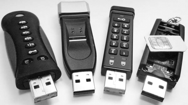
Figure 5-3: Encrypted USB sticks
Proprietary solutions might not have a compatible tool to manage access, making it difficult to acquire decrypted data with Linux. Devices with an onboard authentication mechanism should appear as a normal USB storage device after authentication.
Secure thumb drives that are locked may behave differently when attached to a host. Some don’t provide any indication that they’ve been plugged into the host. Some appear as a removable media device without media (like a memory card reader). Some will appear as a CD-ROM and have software available to run or install, which manages the drive.
Larger hardware-encrypted external drives also exist and may require a pin to unlock. An exmple of such a drive is described in Chapter 7 (see Figure 7-1 on page 216).
Attach Removable Media
This section covers the attachment of devices that use removable storage media. The most common examples of removable media are optical discs, memory cards, and magnetic tapes. In a way, attaching removable storage media to an acquisition host occurs twice. First the device electronics are attached, and then in an additional step, the removable media is inserted. Let’s begin with a discussion on optical media drives.
Optical Media Drives
Optical drives are typically attached internally via SATA or externally via USB. The drives appear in the Linux device tree but without media. Running forensic commands on an empty drive produces obvious results, as shown here:
# mmls /dev/cdrom
Error opening image file (raw_open: file "/dev/cdrom" - No medium found)
Two useful commands provide information about the attached drive and inserted discs. The cd-drive command provides details about an attached optical drive (internal or external), including various features, supported media, and so on:
# cd-drive
cd-drive version 0.83 x86_64-pc-linux-gnu
...
CD-ROM drive supports MMC 3
Drive: /dev/cdrom
Vendor : ASUS
Model : BW-16D1HT
Revision : 1.01
Profile List Feature
Blu Ray BD-RE
Blu Ray BD-R random recording
Blu Ray BD-R sequential recording
Blu Ray BD-ROM
DVD+R Double Layer - DVD Recordable Double Layer
DVD+R - DVD Recordable
DVD+RW - DVD Rewritable
DVD-R - Double-layer Jump Recording
DVD-R - Double-Layer Sequential Recording
Re-recordable DVD using Sequential Recording
Re-recordable DVD using Restricted Overwrite
Re-writable DVD
Re-recordable DVD using Sequential recording
Read only DVD
CD-RW Re-writable Compact Disc capable
Write once Compact Disc capable
Read only Compact Disc capable
...
Removable Medium Feature
Tray type loading mechanism
can eject the medium or magazine via the normal START/STOP command
can be locked into the Logical Unit
...
When you insert a disc into the drive, you can retrieve information about the media using the cd-info command. The result includes the mode, format, and information about the publisher:
# cd-info
cd-info version 0.83 x86_64-pc-linux-gnu
Disc mode is listed as: CD-DA
CD-ROM Track List (1 - 1)
#: MSF LSN Type Green? Copy? Channels Premphasis?
1: 00:02:00 000000 data false no
170: 39:42:20 178520 leadout (400 MB raw, 400 MB formatted)
Media Catalog Number (MCN): 0000000000000
TRACK 1 ISRC: 000000000000
Last CD Session LSN: 0
audio status: invalid
__________________________________
CD Analysis Report
CD-ROM with ISO 9660 filesystem
ISO 9660: 154301 blocks, label `SOLARIS_2_5_1_SPARC '
Application: NOT SPECIFIED
Preparer : SOLARIS_PRODUCT_ENGINEERING
Publisher : SUNSOFT_INC
System : SUNSOFT_INC
Volume : SOLARIS_2_5_1_SPARC
Volume Set : SOLARIS_2_5_1_SERIES
You can eject the optical media using the eject shell command.
Using write blockers on optical drives is unnecessary. No timestamps are updated simply by accessing files on a disc. Modifying an optical disc requires explicit burn instructions, reducing the risk of accidental modification.
Magnetic Tape Drives
You can determine a list of attached tape drives using the lshw tool and the tape class. The output provides information about the drive vendor, serial number, and device information.
In this example, two tape drives are found (LTO and DAT):
# lshw -class tape
*-tape
description: SCSI Tape
product: LTO-5 HH
vendor: TANDBERG
physical id: 0.0.0
bus info: scsi@13:0.0.0
logical name: /dev/nst0
version: Y629
serial: HU1246T99F
capabilities: removable
configuration: ansiversion=6
*-tape
description: SCSI Tape
product: DAT160
vendor: HP
physical id: 0.0.0
bus info: scsi@15:0.0.0
logical name: /dev/nst1
version: WU8A
serial: HU10123NFH
capabilities: removable
configuration: ansiversion=3
Magnetic tape drives are typically SCSI devices, which you can query using standard SCSI commands. The standard tool for controlling tapes is mt, which provides information about the drive status, controls the position of the tape, and ejects the media. The mt tool can provide basic information about the tape, but the tapeinfo tool is more comprehensive. In this example, the mt and tapeinfo tools query the status of an LTO tape drive with a loaded tape:
# mt -f /dev/nst0 status
SCSI 2 tape drive:
File number=1, block number=0, partition=0.
Tape block size 0 bytes. Density code 0x58 (no translation).
Soft error count since last status=0
General status bits on (81010000):
EOF ONLINE IM_REP_EN
# tapeinfo -f /dev/nst0
Product Type: Tape Drive
Vendor ID: 'TANDBERG'
Product ID: 'LTO-5 HH '
Revision: 'Y629'
Attached Changer API: No
SerialNumber: 'HU1246T99F'
MinBlock: 1
MaxBlock: 16777215
SCSI ID: 0
SCSI LUN: 0
Ready: yes
BufferedMode: yes
Medium Type: Not Loaded
Density Code: 0x58
BlockSize: 0
DataCompEnabled: yes
DataCompCapable: yes
DataDeCompEnabled: yes
CompType: 0x1
DeCompType: 0x1
Block Position: 166723430
Partition 0 Remaining Kbytes: 1459056
Partition 0 Size in Kbytes: 1459056
ActivePartition: 0
EarlyWarningSize: 0
NumPartitions: 0
MaxPartitions: 1
The tape head is positioned at the second file on the tape (file 1 is after file 0). The block offset and file offset are useful when you’re forensically acquiring individual files from a tape.
Using mt, you can rewind tapes and take them offline (eject them):
# mt -f /dev/nst0 status
When a tape device is attached to a Linux system, a number of corresponding devices are created.
# ls -1 /dev/*st0*
/dev/nst0
/dev/nst0a
/dev/nst0l
/dev/nst0m
/dev/st0
/dev/st0a
/dev/st0l
/dev/st0m
The st* devices auto-rewind the tape after each command (which is not always desired), and the nst* devices are the nonrewinding devices. The a, l, and m characters represent the same device but with different characteristics (block size, compression). When you’re performing a forensic acquisition, you should use the nst* devices (without an additional a, l, or m character).
Memory Cards
Memory cards typically attach to a host using a USB adapter with multiple slots for different types of memory cards. When attached, the adapter creates a removable SCSI device for each slot (even when the slots are empty). This behavior can be observed in the following dmesg output.
[ 2175.331711] usb 1-7: new high-speed USB device number 10 using xhci_hcd
[ 2175.461244] usb 1-7: New USB device found, idVendor=058f, idProduct=6362
[ 2175.461249] usb 1-7: New USB device strings: Mfr=1, Product=2, SerialNumber=3
[ 2175.461252] usb 1-7: Manufacturer: Generic
[ 2175.461938] usb-storage 1-7:1.0: USB Mass Storage device detected
[ 2175.462143] scsi host15: usb-storage 1-7:1.0
[ 2176.458662] scsi 15:0:0:0: Direct-Access Generic USB SD Reader 1.00
PQ: 0 ANSI: 0
[ 2176.459179] scsi 15:0:0:1: Direct-Access Generic USB CF Reader 1.01
PQ: 0 ANSI: 0
[ 2176.459646] scsi 15:0:0:2: Direct-Access Generic USB SM Reader 1.02
PQ: 0 ANSI: 0
[ 2176.460089] scsi 15:0:0:3: Direct-Access Generic USB MS Reader 1.03
PQ: 0 ANSI: 0
[ 2176.460431] sd 15:0:0:0: Attached scsi generic sg11 type 0
[ 2176.460641] sd 15:0:0:1: Attached scsi generic sg12 type 0
[ 2176.460863] sd 15:0:0:2: Attached scsi generic sg13 type 0
[ 2176.461150] sd 15:0:0:3: Attached scsi generic sg14 type 0
[ 2176.463711] sd 15:0:0:0: [sdj] Attached SCSI removable disk
[ 2176.464510] sd 15:0:0:1: [sdk] Attached SCSI removable disk
[ 2176.464944] sd 15:0:0:2: [sdl] Attached SCSI removable disk
[ 2176.465339] sd 15:0:0:3: [sdm] Attached SCSI removable disk
As you insert media into the slots, the media is made available as a USB mass storage device with a linear sequence of “sectors,” which you can forensically acquire. Continuing on from the previous example, a memory card has now been inserted into a slot of the card reader and appears as block device:
[ 2310.750147] sd 15:0:0:0: [sdj] 7959552 512-byte logical blocks: (4.07 GB/3.79 GiB)
[ 2310.753162] sdj: sdj1
Hardware-querying tools, such as hdparm and smartctl, may produce unreliable results, because memory cards don’t have the ATA features of more complex drives with dedicated drive circuitry.
Attach Other Storage
Sometimes storage media is attached to a forensic acquisition host and behaves in a unique way. In particular, it is useful to know about special behavior with portable devices, Apple computer systems, and NVME drives.
Apple Target Disk Mode
TDM allows Apple computers with OpenBoot firmware or newer firmware to boot into a state where the Mac system appears as an external disk enclosure and the internal disks are available as SCSI target devices. Earlier TDM implementations used the FireWire bus but have since moved to Thunderbolt. You activate this mode by holding down the T key while powering on the Apple computer.
A Linux machine without a Thunderbolt adapter can use FireWire to achieve the same result with an adapter. Figure 5-4 shows a photo of a Thunderbolt-to-FireWire adapter.
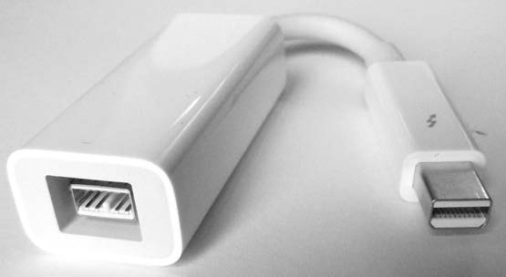
Figure 5-4: Thunderbolt to Firewire adapter
Be sure to boot the Apple device (while holding the T key) with the Thunderbolt-to-FireWire adapter already plugged in; otherwise, the Apple firmware will not use the FireWire adapter for the target device.
The following example shows dmesg output of an Apple notebook in TDM that is connected to a Linux machine using a Thunderbolt to FireWire adapter (Thunderbolt on the Apple; FireWire on the Linux machine):
[ 542.964313] scsi host10: SBP-2 IEEE-1394
[ 542.964404] firewire_core 0000:0e:00.0: created device fw1: GUID
000a27020064d0ef, S800
[ 543.163093] firewire_sbp2 fw1.0: logged in to LUN 0000 (0 retries)
[ 543.163779] scsi 10:0:0:0: Direct-Access-RBC AAPL FireWire Target 0000
PQ: 0 ANSI: 3
[ 543.164226] sd 10:0:0:0: Attached scsi generic sg10 type 14
[ 543.165006] sd 10:0:0:0: [sdj] 236978176 512-byte logical blocks:
(121 GB/113 GiB)
[ 543.165267] sd 10:0:0:0: [sdj] Write Protect is off
[ 543.165271] sd 10:0:0:0: [sdj] Mode Sense: 10 00 00 00
[ 543.165759] sd 10:0:0:0: [sdj] Write cache: enabled, read cache: enabled,
doesn't support DPO or FUA
[ 543.171533] sdj: sdj1 sdj2 sdj3
[ 543.173479] sd 10:0:0:0: [sdj] Attached SCSI disk
PC-based Linux systems with Thunderbolt ports are not common, and Linux kernel support is still under development. As an alternative, you can boot recent Apple computers with a forensic boot CD/USB device and acquire them to a locally attached evidence drive.
NVME SSDs
NVME drives compete with SATA Express in the way they attach directly to a PCI Express bus. As of this writing, hardware write blockers for NVME drives are very new. There are hot-pluggable USB bridges for NVME and SATA Express drives from Tableau (Guidance Software). For illustration purposes, the examples shown here use an NVME device directly attached to a Linux system.
You can use the nvme tool from the nvme-cli software package to list the attached NVME devices:
# nvme list
Node Model Version Namepace Usage ...
---------------- -------------------- -------- -------- --------------------------
/dev/nvme0n1 INTEL SSDPE2MW400G4 1.0 1 400.09 GB / 400.09 GB ...
/dev/nvme1n1 Samsung SSD 950 PRO 1.1 1 3.01 GB / 256.06 GB ...
...
You should also check each NVME drive for multiple namespaces by using the nvme tool. In this example, only a single namespace exists:
# nvme list-ns /dev/nvme1
[ 0]:0x1
Multiple namespaces may need to be acquired individually. This is a fundamental difference from other drives where a single drive is viewed as a linear set of sectors, which you can acquire in a single pass. NVME drives with multiple namespaces will likely need special consideration.8
It’s important to note that the NVME standard was created from scratch without backward compatibility with SCSI or ATA standards (AHCI, and so on). It has its own command set and operates independently from other disk systems. For this reason, some tools may not work as expected with NVME hardware. Any forensic tool operating directly on low-level device drivers, such as SATA or SAS, will not work with NVME. However, if forensic tools operate on the virtual block layer, they should continue to work normally. In addition, PCI forensic write blockers may act as a bridge and make the device appear as a SCSI device. For example, here the Sleuth Kit mmls tool is used on an NVME drive attached to the examination host:
# mmls /dev/nvme1n1
DOS Partition Table
Offset Sector: 0
Units are in 512-byte sectors
Slot Start End Length Description
00: Meta 0000000000 0000000000 0000000001 Primary Table (#0)
01: ----- 0000000000 0000002047 0000002048 Unallocated
02: 00:00 0000002048 0167774207 0167772160 Linux (0x83)
03: 00:01 0167774208 0335546367 0167772160 Linux (0x83)
04: 00:02 0335546368 0500118191 0164571824 Linux (0x83)
Notice that the device is nvme1n1 and not simply nvme1. The namespace of the drive must be specified when you’re using commands on NVME drives.
As with other drives, NVME drives have a SMART log, but you can’t access it with current versions of smartctl (as of this writing). However, you can use the nvme tool to extract the SMART log as follows:
# nvme smart-log /dev/nvme1
Smart Log for NVME device:/dev/nvme1 namespace-id:ffffffff
critical_warning : 0
temperature : 46 C
available_spare : 100%
available_spare_threshold : 10%
percentage_used : 0%
data_units_read : 2,616
data_units_written : 5,874
host_read_commands : 19,206
host_write_commands : 56,145
controller_busy_time : 0
power_cycles : 34
power_on_hours : 52
unsafe_shutdowns : 17
media_errors : 0
num_err_log_entries : 7
The nvme tool has a number of features for querying attached NVME drives. See the nvme(1) manual page or visit https://github.com/linux-nvme/ for more information.
As of this writing, NVME drives are an emerging technology. Because they have numerous benefits in terms of performance and efficiency, they may become more popular in the future.
Other Devices with Block or Character Access
You can image any device that is detected as a block device by the Linux kernel. Some devices will appear as a block device the moment they are attached to the host system. For example, many generic MP3/music players, cameras, and other mobile devices behave in this manner.
Some devices need to be switched into a different “disk” mode before they can become accessible as a block device. Often, you can select this mode from the device’s user interface.
Some USB devices are multifunctional and may provide other USB modes in addition to storage. You might need to switch the mode on these devices to usb-storage before acquiring them. A Linux tool called usb_modeswitch is able to query some multifunction USB devices and switch modes.
Closing Thoughts
In this chapter, you learned to attach a subject drive to an acquisition machine and positively identify the device for imaging. You learned different aspects of PC hardware (USB, PCI, block devices, and so on), how to query your acquisition system, and how to query your drive for firmware and SMART information. I demonstrated the removal of the HPA and DCO as well as various types of security built into the hardware of some drives. You are now equipped with the knowledge necessary to perform a forensic acquisition, which will be the focus of Chapter 6.