Table of Contents for
Practical Forensic Imaging
 Practical Forensic Imaging
Published by
No Starch Press, 2016
Practical Forensic Imaging
Published by
No Starch Press, 2016
- Practical Forensic Imaging
- Practical Forensic Imaging
- Practical Forensic Imaging
- Practical Forensic Imaging
- Practical Forensic Imaging
- Practical Forensic Imaging
- Practical Forensic Imaging
- Practical Forensic Imaging
- Practical Forensic Imaging
- Practical Forensic Imaging
- Practical Forensic Imaging
- Practical Forensic Imaging
- Practical Forensic Imaging
- Practical Forensic Imaging
- Practical Forensic Imaging
- Practical Forensic Imaging
- Practical Forensic Imaging
- Practical Forensic Imaging
- Practical Forensic Imaging
- Practical Forensic Imaging
- Practical Forensic Imaging
- Practical Forensic Imaging
- Practical Forensic Imaging
- Practical Forensic Imaging
- Practical Forensic Imaging
1
STORAGE MEDIA OVERVIEW
This chapter serves as an overview of PC bus systems, common mass storage media, physical connectors and interfaces, and the low-level protocol commands used to communicate with attached storage devices. It also provides the background for understanding the forensic acquisition of storage media described in the rest of the book.
In general, mass storage technologies are grouped into three broad categories: magnetic media, non-volatile memory (flash), and optical media. Storage media can be built into a device or be removable. The device also contains the drive electronics needed to interface with the media. Storage devices are accessed by a system through an internal or external bus or interface.
The chapter begins with overviews of these three storage technologies and touches on key points related to digital forensics. The final two sections describe how these storage devices attach to and communicate with a Linux system, and I discuss items of particular interest to a forensic examiner.
This chapter primarily focuses on modern PC architectures and components. Former popular legacy technologies might be mentioned but not covered in depth. I’ve also limited this overview to computer equipment used in small server environments and by individuals (employees, home users, and so on) rather than covering large enterprise technology. Storage technologies in large enterprise environments are not always suited for traditional disk media forensic imaging; in some cases, the sheer volume of storage space makes traditional acquisition infeasible, and business-critical enterprise systems typically can’t be taken offline like smaller PC-based systems.
Magnetic Storage Media
Magnetic media is the oldest of the three basic storage technologies (preceded by paper tape and punch cards) and is the current leader in capacity. The two primary magnetic storage media types in use today are hard disks and tapes; both provide high capacity and reliability for online storage and offline archival storage.
NOTE
The capacity race between magnetic disks and solid state drives (SSDs) is heating up. During the writing of this book, a 16TB SSD was announced and, when released, could be the world’s largest disk.
Hard Disks
Hard disks have consistently provided higher capacities than other media, such as SSD or optical. As of this writing, 10TB hard disks are available on the consumer market, and higher capacities are expected.
Hard disks are built with rotating platters coated with magnetized material, as shown in Figure 1-1. Multiple platters are stacked on a spindle, and read/write heads on a movable arm (the actuator) can read/write encoded data from/to the magnetic surface. Currently, common hard disk form factor sizes include 3.5 inch, 2.5 inch, and 1.8 inch. Because hard disks are mechanical devices, they’re sensitive to shock, dropping, dust, moisture, and other environmental factors. Typical hard disk failures involve scratched platter surfaces, stuck or damaged heads, motor failure, and failed electronic circuitry.
The real physical geometry (heads, platters, tracks, sectors per track) of the disk is abstracted from the computer and is accessible as a sequence of sectors using Logical Block Addresses (LBA). A sector is the smallest addressable disk unit for reading and writing data. Historically, the standard physical hard disk sector size was 512 bytes; however, modern disks have transitioned to 4K sector sizes. Most current drives continue to provide a 512-byte emulation of the sector size, but drives with a native 4K sector size (known as 4Kn drives) are already on the market. Using 4Kn disks has performance advantages, and it’s likely they’ll someday overtake traditional 512-byte emulated drives. Refer to “Advanced Format 4Kn” on page 41 for more detail about 4Kn disk drives.
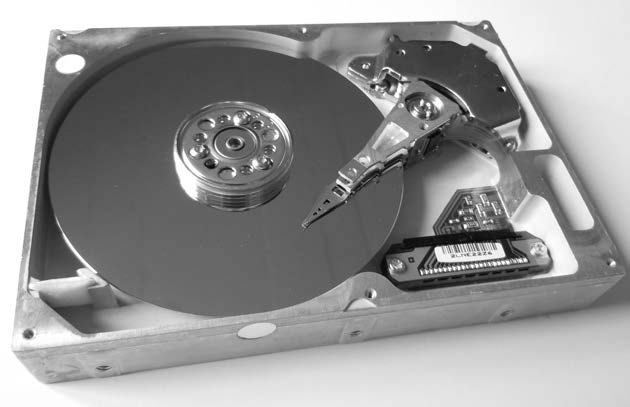
Figure 1-1: Magnetic hard disk
Traditional computer forensics originated from the need to analyze hard disks, which continue to be significant evidence sources today. In particular, when an OS “deletes” a file, it simply unlinks any references to the data blocks on the disk (unlike SSDs, which use a TRIM command to clear unallocated blocks). Those blocks are not erased from the magnetic platters, remaining on the disk where forensic tools can recover them (until they’re overwritten).
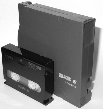
Magnetic Tapes
The use of magnetic tapes in the home user marketplace has nearly disappeared, but small business and enterprise environments continue to use magnetic tapes for backups and archiving. Tapes, as shown in Figure 1-2, are one of the earlier forms of digital storage and have a reputation as a mature technology, reliable for long-term offline storage. Unlike disks, SSD/flash, or optical disks, tapes can only read or write data sequentially. Randomly accessing different blocks on a tape requires the user to rewind or forward the tape to the desired location before it can be read or written. This lack of random block access prevents tapes from being used as regular filesystems. Data is stored on tapes as a sequence of tape files; each file is typically an archive containing a filesystem or group of files and directories (using archive formats, such as TAR, DUMP, and so on.). Tape drives are controlled using SCSI tape commands to read and write data, position or rewind the tape, and eject the tape.
NOTE
Newer Linear Tape-Open, or LTO, drives can simulate a regular filesystem with the Linear Tape File System (LTFS), but this is not random access and files are still sequentially read and written.
Here are some examples of a Fibre Channel LTO5 tape drive and a USB DAT160 tape drive; both are attached to a Linux system. The dmesg output of the tape drives looks like this:
[ 11.290176] scsi 1:0:0:0: Sequential-Access TANDBERG LTO-5 HH
Y629 PQ: 0 ANSI: 6
[ 11.293554] scsi 1:0:0:0: Attached scsi generic sg5 type 1
[ 11.345030] st: Version 20101219, fixed bufsize 32768, s/g segs 256
[ 11.361189] st 1:0:0:0: Attached scsi tape st0
...
[ 3263.575014] usb 1-8: new high-speed USB device number 14 using xhci_hcd
[ 3263.703245] usb 1-8: New USB device found, idVendor=03f0, idProduct=0225
[ 3263.703250] usb 1-8: New USB device strings: Mfr=1, Product=2, SerialNumber=3
[ 3263.703253] usb 1-8: Product: DAT160 USB Tape
[ 3263.703255] usb 1-8: Manufacturer: Hewlett Packard
[ 3263.703257] usb 1-8: SerialNumber: 48553101234E4648
[ 3263.704156] usb-storage 1-8:1.0: USB Mass Storage device detected
[ 3263.704295] scsi host12: usb-storage 1-8:1.0
[ 3264.713397] scsi 12:0:0:0: Sequential-Access HP DAT160
WU8A PQ: 0 ANSI: 3
[ 3264.722279] st 12:0:0:0: Attached scsi tape st1
Once tape archive files have been written, an End Of Data (EOD) marker is also written to the tape. This informs the drive that the end of the tape data has arrived and prevents the drive from reading any further. From a forensics perspective, however, any data beyond the EOD marker is of interest because it may contain data from previous tape writes. No generic SCSI commands are available to acquire data beyond the EOD marker. Specialized tape drives and equipment are needed to complete this task.
Legacy Magnetic Storage
There are many legacy magnetic storage types, especially among removable media. Floppy diskettes evolved over several generations before becoming obsolete. A number of proprietary storage products, such as Jaz, Zip, Syquest, and so on, were popular on the market during the ’80s and ’90s. A large variety of magnetic tapes are no longer in use, for example, 4mm DAT, 8mm Exabyte, and QIC. The forensic acquisition of these storage types is beyond the scope of this book. However, if functioning hardware and interfaces are available, you can acquire the data on most of these older devices using the same techniques described in this book. If the Linux kernel recognizes the sector-based media and it’s made available as a block device, you can acquire it. If the Linux kernel recognizes tape drives as SCSI tape devices, you can access them using standard SCSI tape commands. For proprietary storage, kernel drivers or userspace tools might be available, which can provide you with access to legacy storage products.
Non-Volatile Memory
Non-volatile memory, typically using NAND flash technology, is growing in popularity and starting to replace magnetic hard disks in situations where very large capacities are not needed. (NAND refers to transistors operating as a logical NAND gate.) This type of memory creates a new set of challenges for forensic investigators because it doesn’t exhibit the same low-level properties as magnetic disks.1
SSD and flash media are typically NAND-based storage and have no moving parts. Data is stored in an array of memory cells, and a layer of abstraction, the Flash Translation Layer (FTL), makes the drive behave as a linear sequence of sectors similar to a hard disk. Because non-volatile memory disks are implemented in circuitry and are not mechanical, they are silent, use less power, and do not suffer from the same risk of physical damage as hard disks do. In terms of performance, they can randomly access and write data faster because there are no physical heads seeking to locations on a disk. (This also means there’s no performance advantage to defragmenting filesystems.) The memory in SSD/flash drives doesn’t have the same longevity as the magnetic platters in hard disks. Certain methods, such as wear leveling and over-provisioning, are used to prolong the life of SSD media. Wear leveling refers to the mechanism used to distribute reads and writes across the drive, ensuring blocks are evenly used during the lifetime of the drive. As blocks deteriorate or become unwritable, they’re removed from use by the FTL and replaced with blocks from a pool of reserved (over-provisioned) blocks. These “retired” blocks can be read by removing (desoldering) the physical chips and reading out the memory. Some professional forensic laboratories perform this process, sometimes called chip-off, for various flash-based storage. Over-provisioning of blocks during manufacture can take up to 10 to 25 percent of a flash disk (which is inaccessible to the user). Currently, an open source SSD firmware project exists that is useful for learning and researching the underlying SSD technology. You can find more information about it at http://www.openssd-project.org/wiki/The_OpenSSD_Project.
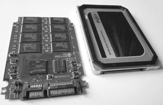
Solid State Drives
The SSD, as shown in Figure 1-3, was designed as a drop-in replacement for regular SATA disks. (SATA, or Serial AT Attachment, is the standard interface for disks.) SSDs have standard SATA interfaces and Self-Monitoring, Analysis and Reporting Technology (SMART) capability and use regular ATA commands (with some additions). Even the physical form factor of common consumer SSDs is the same as that of magnetic hard disks. Newer SSDs pose several challenges to digital forensic examiners, partly in the possibility to recover data from unallocated sectors on the drive and partly in the inability to access over-provisioned areas. SSD devices and OSes that support the ATA TRIM command can cause the erasure of unallocated disk blocks in preparation for the next use (SSD blocks must be erased before they can be written to or modified). This reduces the potential recovery of data in unallocated blocks, which are typically a valuable source of evidence on magnetic disks.
You can use the hdparm command to determine the TRIM features supported by an SSD. For example:
# hdparm -I /dev/sda
...
Commands/features:
Enabled Supported:
...
* Data Set Management TRIM supported (limit 1 block)
* Deterministic read data after TRIM
...
A modern generation of SSDs, based on new standards called SATA Express and NVM Express, interface directly with the PCI Express bus.
USB Flash Drives
Small, portable USB flash drives, as shown in Figure 1-4, are referred to by many names: thumb drives, USB sticks, flash dongles, or simply USB flash drives. Flash drives initially became the replacement for floppy disks and, due to their low price and high capacity, are now replacing CDs and DVDs.
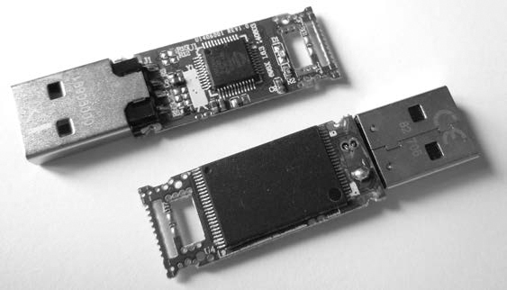
But the small size and large capacity of USB flash drives make them an information security risk. As a result, most vendors offer security solutions involving encryption. The most common encryption is software based and optional. The drive’s owner must explicitly install the encryption software provided by the vendor (or use alternative software, such as BitLocker or TrueCrypt). Some USB sticks provide mandatory hardware-based encryption systems. However, the added work and complexity of software encryption and the significantly higher cost of hardware encryption have impeded their widespread use. Plain, unencrypted USB devices are still most commonly used.
Removable Memory Cards
The popularity of portable devices, such as mobile phones, tablets, cameras, and so on, has created a market for removable memory cards that you can swap out when they’re full or when copying to a PC or another device. A variety of memory cards are shown in Figure 1-5. These are typically flash based and, when placed in a card reader, appear as a linear sequence of sectors similar to a hard disk.
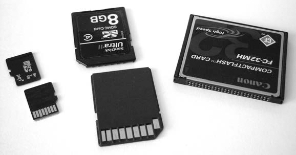
Figure 1-5: Flash memory cards
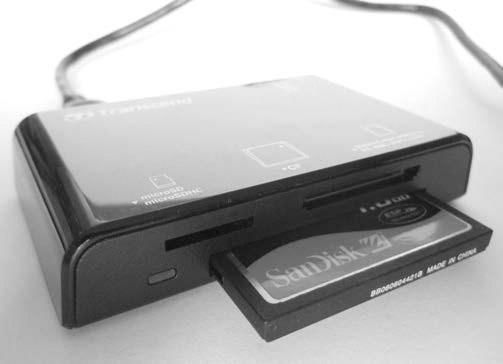
The most common memory card is the Secure Digital (SD) standard, which is available in several form factors and speeds. The CompactFlash (CF) card is popular in high-end camera equipment and is essentially a PATA/IDE interface with a smaller form factor. You can access it using a PATA/IDE interface adapter. A card reader connected via USB provides access to both memory card types (see Figure 1-6).
NOTE
Parallel ATA (PATA) and Integrated Drive Electronics (IDE) are older standards defining a parallel interface between a drive and a computer system.
Legacy Non-Volatile Memory
Many legacy memory cards became obsolete as the market lost interest in their maximum capacity or proprietary interfaces. Some examples include Sony Memory Sticks, Panasonic P2 cards, SmartMedia cards, and other PCMCIA/PCcard media. Typically, these memory cards attach to a Linux system as block devices with a linear sequence of sectors, and you can image them using the same techniques as for other memory cards (if a physical reader is available).
Optical Storage Media
Common optical disc storage media in use today includes CD-ROMs, DVD-ROMs, and Blu-ray discs. The different types of optical media vary in their physical and chemical properties. Their visible differences are shown in Figure 1-7.
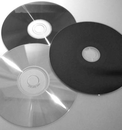
Figure 1-7: Top to bottom: DVD-ROM, Blu-ray, CD-ROM
Optical discs are usually read-only, write-once, or read-writable. Professionally mastered discs are stamped rather than burned. Although they’re slowly becoming obsolete, writable optical discs are still a common source of digital evidence. Many forensic labs still use them for transfer and storage of compressed forensic images.
An optical disc contains a single spiral track with a sequence of pits and lands on a reflective surface, which can be read by a laser and interpreted as data bits. Data is written to the surface using a laser to burn points on the surface, which affects the reflectivity and causes the burned areas to be interpreted as data bits. This sequence of bits is separated into sectors, which after encoding and error correction contain 2048 bytes of user-accessible data.
Optical discs have one similarity to magnetic tapes: data is written as a single linear string of bytes—files are not fragmented. Unlike tapes, it’s possible to easily jump to random areas of the disc, making it feasible to mount the disc as a read-only filesystem. However, writing to an optical disc is still cumbersome and, as with a tape, must be done in a sequential order of bytes.
Compact Discs
The oldest of the three optical discs, CD-ROM/CDR discs, were once the most popular optical media for home user backups, personal archives, and exchanging information. But as the use of convenient, high-capacity USB flash drives has grown, the use of CDs for storage has declined.
A collection of standards called the Rainbow Books describes various CD specifications, and a number of common CD standards exist. (See the Philips intellectual property page at http://www.ip.philips.com/licensing/program/16/ for more information.)
• Music CDs, or Compact Disc-Digital Audio (CD-DA), are specified in the Red Book and IEC 60908 standard. Data in this format is divided into multiple audio tracks.
• Data CDs, or Compact Disc-Read Only Memory (CD-ROM), are covered in the Yellow Book, ISO/IEC 10149, and ECMA 130 standard (http://www.ecma-international.org/publications/files/ECMA-ST/Ecma-130.pdf).
• Writable CDs, or Compact Disc-Recordable/ReWritable (CD-R/CD-RW), are part of the Orange Book standard and allow data to be written (CD-R) or rewritten (CD-RW) to a CD.
• Less common standards include Photo-CD, Video CD (VCD), and other obscure variations, extensions, and enhancements of the common standards.
Every CD has a linear stream of bits (pits and lands) that are abstracted into a linear sequence of sectors. Abstracted further, above these sectors, are sessions, which contain a lead-in area and a table of contents (TOC) for the session. Multisession CDs can exist, and each session has its own TOC.
Data CDs can have filesystems residing on a session, which can contain files and a directory structure. Some examples of CD-ROM filesystems include:
High Sierra Original standard for PCs (8.3, uppercase)
ISO9660 Updated High Sierra for cross-platform
Joliet ISO9660 extensions; from Microsoft for Win95 and later
HFS Macintosh
Rock Ridge Extensions to ISO9660 for POSIX
El Torito Standard for bootable discs
From a forensics perspective, user data on the entire CD can be read. There is no equivalent to the EOD found on tapes or DCO/HPA (user-inaccessible areas of a hard disk) found on disks. But there are filesystem-specific artifacts that might require special analysis to interpret.
Forensic write blockers, which are forensic hardware designed to prevent tampering and contaminating evidence found on drives, are unnecessary for CD-ROMs, given their default read-only properties. The OS will not update timestamps or modify data on a CD simply by putting it into the CD drive and accessing it.
CDs do have some unique identifiers that are useful in a forensic context. A Source Unique Identifier (SID) is stamped on the disc and contains information about the optical disc production facility that produced that particular disc. This code begins with IFPI and is physically stamped on the inner area of the disc (which can be easily read with the human eye). The Recorder Identification Code (RID) is written to system sectors of a disc and links a burned CD to the drive that created it. The RID is not easily accessible without specialized hardware.
Other physical attributes, such as those indicative of piracy and counter-feit copies, are outside the scope of this book, but you can access a guide from the International Federation of the Phonographic Industry (IFPI) at http://www.ifpi.org/content/library/manual-of-guidance-chap3-english.pdf.
Digital Versatile Discs
DVDs have different physical attributes from but are logically similar to CDs. A DVD has a single spiral track of bits split into 2048-byte sectors.
DVDs can be single sided or double sided. They can also be single layer or double layer. Doubling a side or a layer effectively doubles the data capacity. They have similar standards as CDs but with some additions, discussed here: http://www.ecma-international.org/publications/files/ECMA-ST/ECMA-382.pdf. DVD-Video, DVD-ROM, DVD-R, and DVD-RW correspond to their CD equivalents, but an additional DVD-RAM standard is also available. An alternative set of standards was created with DVD+R and DVD+RW, which have the same data capacities as DVD-R and DVD-RW, but the “+” and “-” formats are incompatible (although most modern drives can read both).
The most common filesystem for DVD drives is the Universal Disk Format (UDF), which is designed as a packet-writing replacement for ISO9660.
Blu-ray Discs
Blu-ray discs (BDs) use new physical manufacturing processes to further increase the data capacity of the discs. BD is still similar to CD and DVD in that it uses the spiral track of data split into 2048-byte sectors.
Its standards have close counterparts to CD and DVD and include BD-ROM (Read only), BD-R (Recordable), BD-RE (ReWritable), BD-XL (double capacity ReWritable).
DVD and BD allow for content protection using encryption, which can potentially cause difficulties when acquiring a protected disc during a forensic investigation. Tools and methods to decrypt DRM-protected content exist but are left outside the scope of this book.
Legacy Optical Storage
A number of legacy optical drives exist, in particular, the cartridge-based Write Once, Read Many (WORM) times drive. The legacy optical drives were more commonly used in enterprise environments, typically used SCSI interfaces, and were accessible as a linear sequence of sectors. If the drive and a compatible controller card are still available, and the Linux kernel recognizes the media, you can read and analyze the media in the same manner as other optical discs.
Interfaces and Physical Connectors
In this section, I’ll provide an overview of common drive interfaces from the perspective of a forensic examiner. A forensic examiner working in a well-equipped forensics laboratory can acquire and analyze storage media using a variety of device interfaces.
A general trend in computing (especially with storage interfaces) is the shift from parallel and shared buses to serial point-to-point connections. PATA/IDE, a once-popular parallel interface with two disks sharing a single cable, has been replaced by SATA, which has one disk on a serial cable. SCSI was a parallel shared bus that supported multiple disks and has now been replaced by SAS with individual serial connectors for each disk. The original PCI bus was parallel and shared by multiple interface cards but has been replaced by PCI Express, a serial bus with dedicated lanes per interface (also used to attach SATA Express and NVM Express drives). The parallel printer interface has been replaced by USB (a serial protocol, but using a shared bus). As transmission speeds increased, the timing of parallel electrical signals became difficult to manage. Performing serialization/deserialization of data over dedicated serial lines enabled faster transmission speeds than managing the coordination of multiple parallel data lines.
Serial ATA
The most popular internal storage media interface in use today is SATA. Inside PCs, most hard disks, SSDs, and optical drives connect to SATA interfaces on the mainboard or add-on host bus adapters. The serial architecture of SATA has replaced parallel ATA (PATA or IDE), which used to be the dominant consumer disk interface.
The SATA standard is managed by The Serial ATA International Organization (http://www.sata-io.org/). Currently in revision 3, SATA provides speeds of up to 6Gbps (revisions 1 and 2 had speeds of 1.5Gbps and 3.0Gbps, respectively). In addition to the internal interface, an external interface (eSATA) exists that allows you to directly attach external SATA disks. Figure 1-8 shows the SATA interface.
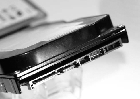
Figure 1-8: SATA disk interface
A smaller form factor, mini-SATA (mSATA), was designed for small portable devices. mSATA, shown in Figure 1-9, allows small SSD SATA drives to attach directly to a mainboard without separate SATA cabling.
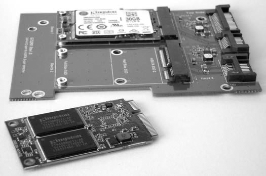
Figure 1-9: mSATA disk interface
Mainboards typically allow you to install SATA disks in either Advanced Host Controller Interface (AHCI) mode or IDE mode. AHCI defines a standard SATA adapter interface here: http://www.intel.com/content/dam/www/public/us/en/documents/technical-specifications/serial-ata-ahci-spec-rev1-3-1.pdf. IDE mode provides a legacy disk interface for older OSes that don’t support the AHCI standard (old versions of Windows XP, for example). The mode you use doesn’t affect the cryptographic hash of a forensic image. You can remove a disk from a subject PC in IDE mode, attach it to an examiner machine in AHCI mode, and acquire it without data loss or modification.
Another interface, micro SATA (not to be confused with mSATA), is shown in Figure 1-10. It was designed for 1.8-inch disk drives and slim CD/DVD players but is less commonly used today. You can combine regular SATA write blockers with various adapters to acquire mSATA and micro SATA drives.
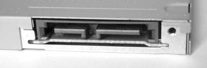
Figure 1-10: Micro SATA disk interface
A more advanced form factor gaining in popularity is the M.2 interface, shown in Figure 4-4. Introduced with the SATA 3.2 specification, M.2 provides two standards in one interface. An M.2 card can use either AHCI/SATA or NVMHCI/NVME interfaces, depending on compatibility requirements. When you’re using M.2 cards, be sure to confirm which interface the card uses (as of this writing, most M.2 cards on the market use ACHI/SATA mode).
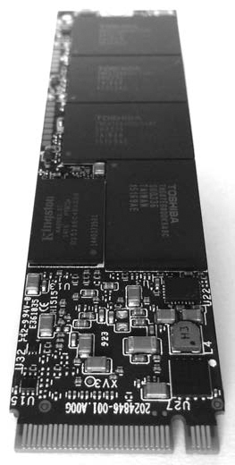
Figure 1-11: M.2 disk interface
The SATA Express disk interface, shown in Figure 1-12, eliminates several layers of the SATA protocol stack, allowing storage (primarily SSDs) to attach directly to the PCI Express bus. These drives continue to use the AHCI standard and are different from NVME.
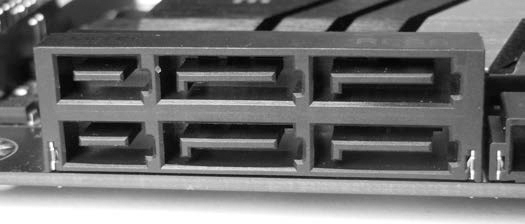
Figure 1-12: SATA Express disk interface
The SATA 3.2 specification supports two PCI Express lanes for 16Gbps SATA Express speeds. Write blockers exist for PCI- and M.2-based SATA Express drives.
Serial Attached SCSI and Fibre Channel
The parallel SCSI interface has largely disappeared in both consumer and enterprise markets. SATA has replaced it in the consumer market, and Serial Attached SCSI (SAS) and Fibre Channel (FC) have replaced it in the enterprise market. The physical connector of the SAS interface, shown in Figure 1-13, allows both SAS and SATA disks to be attached and accessed on a SAS backplane. The physical connector on SAS disk drives is slightly different from that on SATA disks, and various fan-out connectors are available for attaching multiple disks to the host bus adapter. The current speed of SAS-3 disks is 12Gbps, twice that of SATA-3. SAS-4 will provide speeds of 22.5Gbps.
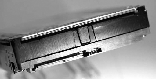
Figure 1-13: SAS disk interface
A Mini-SAS HD 4i receptacle connector is shown in Figure 1-14.
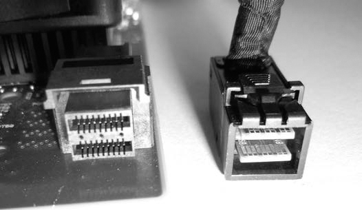
Figure 1-14: SFF-8632/Mini-SAS HD interface
The SAS standard is maintained by the T10 technical committee of the International Committee for Information Technology Standards (INCITS). The current standards document is “Serial Attached SCSI -3 (SAS-3) INCITS 519-2014.” More information, including drafts of upcoming standards, is available at http://t10.org/.
SAS drives cannot be connected to SATA host bus adapters, and separate SAS write blockers are needed to image SAS disks.
The Fibre Channel interface is often used to connect enterprise storage arrays. Shown in Figure 1-15 are copper and optical-based Fibre Channel connectors.
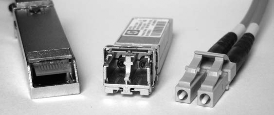
Figure 1-15: Fibre Channel interfaces
Hard disks with integrated Fibre Channel interfaces are becoming legacy and have largely been replaced with SAS drives. As of this writing, no hardware write blockers for Fibre Channel disk interfaces are available on the market.
Non-Volatile Memory Express
Non-Volatile Memory Express (NVME) was designed from the ground up as an alternative to the AHCI-based SATA drive interface. It was designed to attach directly to the PCI Express bus, eliminating the need for an AHCI/SATA host bus adapter and the associated SATA physical interfaces and protocol layers. The NVME architecture focuses specifically on SSD storage, and a simpler, more efficient command set was created. NVME devices can attach either directly to a mainboard in a PCIE slot, using the PCIE NVMe mode of an M.2 interface, or with a U.2 (SFF-8639) interface.
The physical interface is directly attached to the PCIE bus, as shown in Figure 1-16.
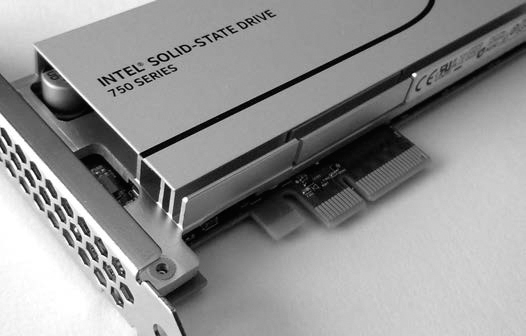
Figure 1-16: NVME SSD with a PCIE interface
An M.2 or Next Generation Form Factor (NGFF) version is also available. These are either directly inserted into mainboard M.2 slots or using PCIE slot adapter cards, both with NVME mode (not AHCI/SATA mode). Currently, most M.2 SSD disks are AHCI/SATA, not NVME, but this may change because the performance benefits of NVME are compelling. Figure 1-17 shows an NVME M.2 disk.
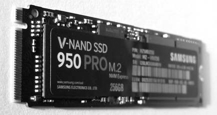
Figure 1-17: NVME SSD with an M.2 interface
The NVME U.2 interface (see Figure 1-18) allows drives with traditional 2.5-inch physical form factors to connect via cable or backplane. The U.2 (SFF-8639) interface and cable (mechanically similar to SAS but with additional pins for PCIE lanes) connect the drive enclosure to a mini-SAS HD plug on an M.2 adapter, which is attached to the mainboard.
Figure 1-18: A 2.5-inch SSD with a U.2 interface, a U.2 to mini-SAS HD cable, and a mini-SAS HD to M.2 adapter for a mainboard
NVME disks are not visible using typical SCSI or SATA command tools because they don’t use SCSI or SATA commands. Linux tools designed to interact with ATA or SCSI disk interfaces will generally not work with NVME disks and require added support for compatibility. The device names for NVME disks are not the familiar /dev/sd* files but /dev/nvme*n*. An NVME device is created with an additional namespace number. The namespace, denoted with n, is a lower layer (below the OS) allocation of space on an NVME drive. The /dev/nvme*n* disk devices are block devices and should function normally when applied to the Linux device file. For example, here is the Sleuth Kit mmls command operating on an NVME disk:
# mmls /dev/nvme0n1
DOS Partition Table
Offset Sector: 0
Units are in 512-byte sectors
Slot Start End Length Description
00: Meta 0000000000 0000000000 0000000001 Primary Table (#0)
01: ----- 0000000000 0000002047 0000002048 Unallocated
02: 00:00 0000002048 0781422767 0781420720 Linux (0x83)
#
As of this writing, the use of NVME is relatively new, and Tableau has just created the first PCI Express forensic hardware write blocker with NVME support. The difficulty intercepting NVME commands on the PCIE bus makes write blockers expensive and complex to implement. For more information, see my paper “NVM Express Drives and Digital Forensics,” which discusses this challenge in more detail.2
Universal Serial Bus
USB was created to consolidate and replace aging external peripheral interfaces, such as RS-232, the parallel printer interface, PS/2 keyboard and mouse, and other proprietary PC interfaces. It was designed to accommodate multipurpose functionality, such as disks, keyboards, mice, sound, network connections, printers and scanners, and connected small devices (mobile phones and so on). A growing number of Internet-of-Things (IoT) devices can be attached to a PC via USB and may contain data useful as forensic evidence. Because the focus of this book is on the forensic acquisition of mass storage devices, I’ll limit this discussion to USB mass storage devices.
Flash drives, optical drives, some tape drives, and even magnetic hard disks (see Figure 1-19) may have a USB interface directly integrated into the drive electronics. The most common uses of the USB mass storage class are the consumer USB stick, or thumb drive, and external hard disk enclosures.
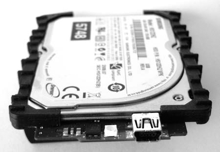
Figure 1-19: A 1.8-inch magnetic hard disk with integrated USB interface
The original USB protocol for the mass storage class of devices is known as Bulk-Only Transport (BOT). BOT is currently the most common USB transport protocol; however, with increasing disk speeds and the arrival of USB3, the BOT protocol is becoming a bottleneck and may be replaced by the USB Attached SCSI Protocol (UASP). Similar to AHCI for SATA, USB also has a defined standard for the host controller interface. The Extensible Host Controller Interface (xHCI) replaces several older USB standards (in particular, OHCI, UHCI, and EHCI). Its specification can be found at http://www.intel.com/content/dam/www/public/us/en/documents/technical-specifications/extensible-host-controler-interface-usb-xhci.pdf.
The latest USB interface for USB 3.1 is Type C, shown in Figure 1-20. The Type C interface is multifunctional and can be used for USB 3.1 devices and Thunderbolt 3 devices, and as a power supply. The physical plug is reversible, meaning it does not have a top or bottom to align when plugging in to a system.
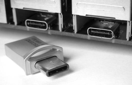
Figure 1-20: USB Type C interface
External USB disk enclosures typically contain one or more SATA drives. If feasible, you should remove SATA disks to gain direct access to the ATA interface. This allows you to directly query the drive interface and may have performance advantages in some cases (for example, USB 2.0 enclosures containing a SATA disk).
Forensic write blockers designed specifically for imaging USB devices exist and can be used for drives (flash or otherwise) that have integrated USB interfaces.
Thunderbolt
Thunderbolt was developed jointly by Apple and Intel as a high-speed external interface to connect disks, video displays, and PCI Express devices using a single interface (see Figure 1-21). Using the code name Light Peak, it was originally intended to be a fiber optic connection. The physical interface uses Mini DisplayPort for Thunderbolt 1 and Thunderbolt 2, and it transitions to the USB Type C cable and connector for Thunderbolt 3. Apple is largely responsible for the popularity of Thunderbolt (primarily among Apple users), promoting it with Apple hardware. The Thunderbolt 3 interface combines PCI Express, DisplayPort, and USB3 into a single interface. Thunderbolt 1, 2, and 3 offer speeds of 10, 20, and 40Gbps, respectively.
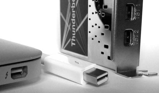
Figure 1-21: Thunderbolt interface
For Apple computer systems, you can use Target Disk Mode (TDM) with Thunderbolt (as with FireWire) to make the system behave as an external disk enclosure to another connected system. TDM instructs the Apple firmware to make the internal disks available as block devices, which can be accessed as external SCSI drives (useful when using forensic tools). I’ll demonstrate the forensic acquisition of an Apple computer using TDM in “Apple Target Disk Mode” on page 137.
Thunderbolt external disks typically contain one or more SATA drives. In large thunderbolt RAID enclosures, the interface may use a SAS controller together with multiple SATA or SAS disks.
The Linux dmesg output of an external disk attached with a Thunderbolt interface looks like this:
[ 53.408619] thunderbolt 0000:05:00.0: 0:1: hotplug: scanning
[ 53.408792] thunderbolt 0000:05:00.0: 0:1: is connected, link is up (state: 2)
[ 53.408969] thunderbolt 0000:05:00.0: initializing Switch at 0x1 (depth: 1,
up port: 1)
...
[ 53.601118] thunderbolt 0000:05:00.0: 1: hotplug: activating pcie devices
[ 53.601646] thunderbolt 0000:05:00.0: 0:6 <-> 1:2 (PCI): activating
...
[ 53.602444] thunderbolt 0000:05:00.0: path activation complete
[ 53.602679] pciehp 0000:04:03.0:pcie24: Card present on Slot(3-1)
[ 53.609205] pciehp 0000:04:03.0:pcie24: slot(3-1): Link Up event
...
[ 56.375626] ata7: SATA link up 6.0 Gbps (SStatus 133 SControl 300)
[ 56.382070] ata7.00: ATA-8: ST1000LM024 HN-M101MBB, 2BA30003, max UDMA/133
[ 56.382074] ata7.00: 1953525168 sectors, multi 0: LBA48 NCQ (depth 31/32), AA
[ 56.388597] ata7.00: configured for UDMA/133
[ 56.388820] scsi 7:0:0:0: Direct-Access ATA ST1000LM024 HN-M 0003 PQ: 0
ANSI: 5
[ 56.389341] sd 7:0:0:0: Attached scsi generic sg2 type 0
[ 56.389342] sd 7:0:0:0: [sdc] 1953525168 512-byte logical blocks:
(1.00 TB/931 GiB)
[ 56.389345] sd 7:0:0:0: [sdc] 4096-byte physical blocks
[ 56.389408] sd 7:0:0:0: [sdc] Write Protect is off
[ 56.389413] sd 7:0:0:0: [sdc] Mode Sense: 00 3a 00 00
[ 56.389449] sd 7:0:0:0: [sdc] Write cache: enabled, read cache: enabled, doesn't
support DPO or FUA
[ 56.403702] sdc: [mac] sdc1 sdc2
[ 56.404166] sd 7:0:0:0: [sdc] Attached SCSI disk
At the time of this writing, the Linux kernel supports Thunderbolt interfaces on Apple computers. Add-in cards for PC mainboards, such as ASUS ThunderboltEX II, do not support the hot plugging of devices. However, booting the PC with the Thunderbolt disk attached allows the PC’s BIOS/firmware to initialize the Thunderbolt adapter before the OS loads, making external disks visible to the kernel.
As of this writing, no write blockers are on the market for Thunderbolt interfaces. Also, no disks are currently available with directly integrated Thunderbolt interfaces (enclosures only).
Legacy Interfaces
This section does not discuss the long history of computer disk interfaces; instead, it briefly covers the recently obsoleted IDE, parallel SCSI, and FireWire technologies. These interfaces may still be relevant in the context of a forensic investigation as older hardware is discovered or seized as evidence.
The IDE interface (see Figure 1-22) and Enhanced version (EIDE) typically used for 3.5-inch disks were popular interfaces until they were replaced by SATA.
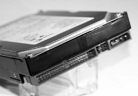
Figure 1-22: IDE disk interface
The mini IDE interface (see Figure 1-23) was developed for 2.5-inch disks for use in notebook computers until it was replaced by SATA.
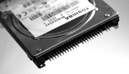
Figure 1-23: Mini IDE disk interface
The micro IDE ZIF interface (see Figure 1-24) was developed for 1.8-inch hard disks in sub-notebooks and other small electronic devices until it was replaced by mSATA and M.2 interfaces.
Figure 1-24: Micro IDE ZIF interface
The FireWire, or IEEE1394, interface (see Figure 1-25) was developed by Apple to provide a high-speed external bus to connect video equipment and disk drives. This interface has largely been replaced by Thunderbolt and USB3.
Figure 1-25: Firewire interfaces
The parallel SCSI interface (see Figure 1-26) has largely disappeared from the consumer market and has been replaced primarily by SATA (or SAS in the enterprise market).
Forensic write blockers for IDE, SCSI, and FireWire are common and also function with adapters for mini IDE, micro IDE ZIF, and various SCSI interface adapters.
Commands, Protocols, and Bridges
The communication between storage devices and computer systems has some conceptual similarities to LAN/WAN layered networking.3 The communication between storage devices and computer systems can be similarly organized into several layers of abstraction. There is a physical layer consisting of cables, wires, and electrical signals. Above that, there is a link layer where digital bits and bytes are transmitted in an organized manner using frames or link layer packets. On top of the link layer, protocols and commands are exchanged between a sender and receiver to request and receive data. In previous sections, I described the physical connections and disk interfaces. Here, I’ll describe the higher-layer command sets for ATA, SCSI, and NVME. Figure 1-27 puts the different layers of abstraction into better perspective.
ATA Commands
The current Advanced Technology Attachment (ATA) commands originally evolved from the American National Standards Institute (ANSI) standard, which defined the AT Attachment interface for disk drives.4 The original standard described the physical interface (cables, pins, and so on), electrical signals, and logical commands that could be issued. The current standard5 describes feature sets that drives may have and the ATA commands available to control each drive. The ATA Packet Interface (ATAPI) adds a packet command feature set to the ATA standard, allowing additional commands not specific to disk drive functionality (for example, ejecting media, encapsulating SCSI commands, and so on).
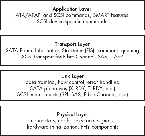
Figure 1-27: Abstraction layers as applied to disk interfaces
The ATA Command Set (ACS) defines a set of commands and parameters that can be loaded into ATA registers and sent to a drive for execution. Some common ATA commands are shown in Table 1-1.
Table 1-1: Common ATA Commands
Command |
Command code |
DEVICE RESET |
08h |
READ SECTOR(S) |
20h |
WRITE SECTOR(S) |
30h |
SEEK |
70h |
DOWNLOAD MICROCODE |
92h |
MEDIA EJECT |
EDh |
SECURITY UNLOCK |
F2h |
A number of ATA and ATAPI commands can be issued using the hdparm and smartctls utilities. T13 (http://t13.org/) publishes the standard that defines the full set of commands. You can find additional resources at http://sata-io.org/.
Understanding the basic operation of ATA/ATAPI commands provides the background knowledge you need to understand how SATA and IDE forensic write blockers function (preventing ATA/ATAPI commands from modifying disks). Knowing how these commands operate also improves your understanding of how a forensic examiner can query the attributes of a disk and ultimately perform a successful forensic acquisition.
SCSI Commands
SCSI commands from a host bus adapter to a disk follow a client/server model. The host bus adapter (HBA) is the client, or initiator, and the disk is the server, or target. The initiator sends commands (possibly together with data) to the target, and the target returns a response (possibly together with data). SCSI was originally designed for use with a variety of devices, including scanners, tapes, printers, and so on, not just hard disks. Therefore, SCSI has a rich command set. Commands are sent from the initiator (HBA) to the target (drive) using a command descriptor block (CDB), which is a block of data containing the command and its parameters. The target receives the CDB, carries out the request, and returns a response. The interaction is somewhat similar to a UDP-based request/response in a TCP/IP client/server architecture.
SCSI commands exist to read and write blocks of data from/to a disk, control hardware (ejecting CDs or changing tapes), report status and diagnostic information, and so on. These commands are generally hidden from the end user, but various utilities are available to issue SCSI commands from user space. It’s even possible to submit arbitrary commands from the Linux command line using tools from the sg3_utils software package. For example, the following command submits a low-level SCSI command to read the first sector of a SCSI disk:
# sg_raw -r 512 /dev/sda 08 00 00 00 01 00
SCSI Status: Good
Received 512 bytes of data:
00 00 00 00 00 00 00 00 00 00 00 00 00 00 00 00 00 ................
10 00 00 00 00 00 00 00 00 00 00 00 00 00 00 00 00 ................
...
1a0 00 00 00 00 00 00 00 00 00 00 00 00 00 00 00 00 ................
1b0 00 00 00 00 00 00 00 00 00 00 00 00 00 00 00 00 ................
1c0 02 00 ee ff ff ff 01 00 00 00 ff ff ff ff 00 00 ................
1d0 00 00 00 00 00 00 00 00 00 00 00 00 00 00 00 00 ................
1e0 00 00 00 00 00 00 00 00 00 00 00 00 00 00 00 00 ................
1f0 00 00 00 00 00 00 00 00 00 00 00 00 00 00 55 aa ..............U.
In this example sg_raw is given a CDB command to be sent to /dev/sda, a SAS disk. The first byte, 0x08, specifies the 6-byte long SCSI READ command. The subsequent zeros specify the LUN and starting sector. The 0x01 specifies the number of sectors to read, and -r 512 tells sg_raw how many bytes to display. This example should also work on SAS-, SATA-, and USB-attached drives.
Technical standards for SCSI and SAS commands are maintained by the Technical Committee T10 of INCITS (InterNational Committee for Information Technology Standards). You can find these standards at http://t10.org/. Books on SCSI programming are useful to better understand the SCSI command protocol.
Understanding the basic operation of SAS/SCSI commands is relevant to this book. It provides the background knowledge to understand how SAS/SCSI forensic write blockers function (preventing SAS/SCSI commands from modifying disks). Knowing how SAS/SCSI commands operate improves your understanding of how a forensic examiner can query the attributes of a disk and ultimately perform a forensic acquisition.
SCSI commands are also used to control tapes and optical devices.
NVME Commands
The NVME command set was created from scratch without providing backward compatibility for existing SCSI or ATA command sets. It was designed to support SSD media directly attached to the PCI express bus and to take advantage of parallelization with multiple CPUs and instant SSD seek times (no latency overhead from moving disk heads). The standard’s developers also recognized that with the drive connected directly to the PCIE bus, much of the protocol overhead in ATA or SCSI could be eliminated. A new minimal command set was created, free of legacy commands or backward compatibility requirements. The performance and efficiency of NVME drives is a significant improvement over SATA or SAS. An extensive command queuing system provides up to 64k queues able to hold 64k commands each (in contrast, SATA had 32 queues with one command each).
A translation reference between SCSI and NVME commands is available at http://nvmexpress.org/. Table 1-2 shows the more common examples.
Table 1-2: SCSI and NVME Command Comparison
SCSI |
NVME |
COMPARE AND WRITE |
Compare and Write |
READ |
Read |
WRITE |
Write |
WRITE BUFFER |
Firmware Image Download, Firmware Image Activate |
INQUIRY |
Identify |
READ CAPACITY |
Identify |
REPORT LUNS |
Identify |
MODE SENSE |
Identify, Get Features |
LOG SENSE |
Get Features, Get Log Page |
SYNCHRONIZE CACHE |
Flush |
FORMAT UNIT |
Format NVM |
Disk devices can be attached to a PC system through various bus systems and bridges. Performance can be increased by attaching the drive as close as possible to the CPU and memory. Today, the closest a drive can get to the CPU and memory is through dedicated lanes of the PCI express 3.0 bus using the NVME interface (RAM disks are faster and more efficient, but they are created by the OS and are not non-volatile storage media devices). An NVME device can be directly attached to the CPU without using a southbridge chipset or any traditional disk protocol overhead, such as ATA or SCSI.
Bridging, Tunneling, and Pass-Through
ATA and SCSI are the two most common protocols for interacting with storage media. The commands can be sent over a variety of physical layer buses or transport layers, or even tunneled or encapsulated within other protocols. This complexity is hidden from the user, and attached devices can simply be accessed through standard block devices that the Linux kernel makes available.
To illustrate, consider a SATA hard disk plugged into a stand-alone USB docking station, which is plugged into an external port of a USB3 PCI express card installed in a PC. The communication between the disk interface and the dock is a lower-layer SATA protocol, using SATA Frame Information Structures (FIS) packets. The communication between the dock and the USB3 card is a lower-layer USB protocol, using BOT or USAP. The communication between the USB3 card and the PC is a lower-layer PCI express protocol, using PCIE Transaction Layer Packets (TLP) and Data Link Layer Packets (DLLP). Finally, the disk is accessed across all these bridges using the SCSI command protocol. In this example, multiple physical and link layers are used to connect the disk. To the user, the disk appears directly accessible, and the lower protocol layers are hidden or abstracted from view.
NOTE
FIS are part of the SATA protocol. PCI Express has its own set of protocols, which include TLP and DLLP.
For each of the different physical buses, a device called a PHY (for physical) facilitates communication between devices connected to a bus (the PHYs on a bus work a bit like two modems communicating over a WAN cable). The PHY converts the digital ones and zeros into compliant electrical signals expected for that bus. After the PHY has taken care of the physical layer, a link layer protocol manages the stream of bits/bytes that is being transferred back and forth on the bus. This link layer organizes the data stream into frames or discrete packets of information that upper layers can process.
There are physical and link layer descriptions for USB, PCIE, Thunderbolt, SAS, SATA, Fibre Channel, and so on. Typically, standards exist that allow generic OS drivers to use the physical hardware in a device-independent way. For example, USB adapters are defined by the xHCI standard, SATA adapters are defined by the AHCI standard, NVME devices are defined by the NVMHCI standard (now simply called the NVME standard), and so on. Compliance with these standards allows hardware to be supported without the need for additional proprietary drivers.
Although ATA/ATAPI and SCSI are distinct command sets, they both support some degree of tunneling and pass-through of each other’s commands. ATA uses the ATAPI interface to encapsulate SCSI commands for communication with devices, such as optical drives, tape drives, and other devices that understand SCSI commands for ejecting media and other commands not found in the ATA protocol. SCSI supports ATA pass-through, which allows ATA commands to be sent over the SCSI protocol. SAT (SCSI-ATA Translation) creates a bilateral translation between SCSI and ATA commands where the commands interact with storage media. This translation is implemented as a Linux kernel API within the libata library. (The libata library, sometimes spelled libATA, provides a number of features for interfacing with ATA controllers and devices.)
Bridges play an important role in forensic acquisition because they’re the basis for implementing hardware write blockers. A hardware write blocker is typically a bridge capable of intercepting ATA or SCSI commands sent to the disk, preventing commands from modifying sectors on a disk.
Special Topics
This section covers a number of special topics related to mass storage and digital forensics. Some areas, such as UASP and SSHD, are briefly commented on regarding their relevance to digital forensics. Other areas, such as DCO, HPA, and NVME drives, are introduced here and discussed in more detail later in the book.
DCO and HPA Drive Areas
As the ATA/ATAPI standards evolved, certain features were created to benefit system vendors. The Host Protected Area (HPA) was introduced in the ATA/ATAPI-4 standard and allowed system vendors to reserve portions of the disk for use outside the normal OS. For example, the HPA can be used to store persistent data, system recovery data, hibernation data, and so on. Access to this data is controlled by the system firmware rather than the installed OS. The Device Configuration Overlay (DCO) feature was introduced in the ATA/ATAPI-6 standard and provided the ability to control reported disk features and capacity. This allowed system vendors to ship disks from multiple manufacturers while maintaining identical numbers of user-accessible sectors and features across the disks. This facilitated easier support and drive replacement. Both the HPA and DCO can coexist; however, the DCO must be created first, followed by the HPA.
The HPA and DCO have been misused by criminals and malicious actors to hide illicit files and malware code. I describe how to detect and remove the HPA and DCO, revealing sectors hidden from normal user view, in “Enable Access to Hidden Sectors” on page 118. You’ll find a more detailed description of the HPA and DCO related to forensics in the paper “Hidden Disk Areas: HPA and DCO.”6 Information is also available about nation state exploitation using the HPA at https://www.schneier.com/blog/archives/2014/02/swap_nsa_exploi.html and https://leaksource.files.wordpress.com/2013/12/nsa-ant-swap.jpg.
Drive Service and Maintenance Areas
Certain maintenance areas of a hard disk are generally not accessible using standard Linux tools. These areas contain bad sectors lists and vendor service sectors (sometimes referred to as negative sectors). To access these areas of the disk, you’ll need specialized disk diagnostic software and hardware. I show an example of accessing the service area of a disk and provide some additional resources in “Drive Service Area Access” on page 122. Don’t confuse the service area of a disk with the HPA or DCO. You can easily access HPA and DCO areas using standard ATA commands and methods, but not the service areas of a disk.
USB Attached SCSI Protocol
USB provides two modes for accessing mass storage class devices: the more common BOT and the newer UASP. With the increased speeds of USB3 and USB3.1, a new and more efficient USB mass storage class transport protocol was developed called USB Attached SCSI Protocol (UASP). This new protocol is also referred to as UAS and the product-marketing nicknames USB3 Boost, USB3 Turbo, or USB3 Extreme are sometimes used. You’ll find more information at http://usb.org/ and http://t10.org/, the organizations that jointly developed the standard. UASP improves performance by providing command queuing and asynchronous processing and by improving task and command control capability.
The dmesg output of an attached UASP-enabled USB disk uses the uas protocol for operation:
[15655.838498] usb 2-6.2: new SuperSpeed USB device number 6 using xhci_hcd
...
[15655.952172] scsi host14: uas
...
[15666.978291] sd 14:0:0:0: [sdk] 3907029168 512-byte logical blocks:
(2.00 TB/1.81 TiB)
...
[15667.033750] sd 14:0:0:0: [sdk] Attached SCSI disk
In contrast, the same disk connected with a traditional BOT USB interface loads the usb-storage protocol for operation:
[15767.853288] usb 2-6.2: new SuperSpeed USB device number 7 using xhci_hcd
...
[15767.918079] usb-storage 2-6.2:1.0: USB Mass Storage device detected
[15767.918195] usb-storage 2-6.2:1.0: Quirks match for vid 174c pid 55aa: 400000
[15767.918222] scsi host15: usb-storage 2-6.2:1.0
...
[15777.728944] sd 15:0:0:0: [sdk] 3907029168 512-byte logical blocks:
(2.00 TB/1.81 TiB)
...
[15777.820171] sd 15:0:0:0: [sdk] Attached SCSI disk
From a forensics perspective, it’s important to note that the transport protocol used does not affect the contents of the USB disk and has no effect on the cryptographic hash of the forensic image. In fact, it is advantageous to use UAS-based write blockers for the performance benefits (Tableau USB3 write blockers use UAS, for example).
NOTE
One word of advice: when you’re using the higher speeds of USB3, the quality of the USB cables becomes an issue. Longer, lower-quality USB3 cables can produce read errors during acquisition. For those working in a professional forensic laboratory, it’s worth investing in short, high-quality USB3 cables.
Advanced Format 4Kn
As disk capacities increased, the industry discovered that it could improve disk efficiency by switching from 512-byte sectors to 4096-byte sectors. The International Disk Drive Equipment and Materials Association (IDEMA) developed the Advanced Format standard for 4096-byte physcial sectors (see http://www.idema.org/?page_id=2369). Since 2009, hard disk manufacturers have committed to using IDEMA’s Advanced Format standard to produce 4K sector disks. Even with 4K physical sectors, most disks today emulate 512-byte sectors and are called Advanced Format 512e disks. Disks that provide the host system and OS with native 4K-sized sectors are called Advanced Format 4Kn disks. Advanced Format 4Kn disks are still rare in the low-end marketplace but are used in enterprise environments. For higher-capacity enterprise disks, most enterprise disk manufacturers offer two models: 512e and 4Kn. Figure 1-28 shows the official logo for 4Kn disks.
You’ll find a good overview of Advanced Format and 4K sectors on YouTube at https://www.youtube.com/watch?v=TmH3iRLhZ-A/.
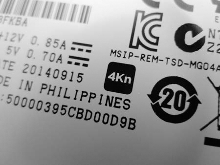
Figure 1-28: Advanced Format 4Kn logo
When the Linux kernel detects an attached disk, it displays the number of sectors and the logical sector size (in some cases, it may also explicitly display the physical size). The following partial dmesg output shows two equal-sized disks, one with Advanced Format 512e and the other with 4Kn. Dividing the number of 512-byte sectors by 8 or multiplying the number of 4K sectors by 8 shows the disks are equal in capacity but have different sector counts.
...
[ 13.605000] scsi 1:0:1:0: Direct-Access TOSHIBA MG03SCA300 0108 PQ: 0
ANSI: 5
...
[ 16.621880] sd 1:0:1:0: [sdb] 5860533168 512-byte logical blocks: (3.00 TB/2.73
TiB)
...
[ 14.355068] scsi 1:0:2:0: Direct-Access ATA TOSHIBA MG04ACA3 FP2A PQ: 0
ANSI: 6
...
[ 16.608179] sd 1:0:2:0: [sdc] 732566646 4096-byte logical blocks: (3.00 TB/2.73
TiB)
On a Linux system, you can use the /sys pseudo filesystem to find the logical and physical sector sizes of a disk. For example, you can determine the physical and logical sector sizes of the attached disk /dev/sda as follows:
# dmesg
...
[ 16.606585] sd 1:0:0:0: [sda] 7814037168 512-byte logical blocks: (4.00 TB/3.64
TiB)
...
# cat /sys/block/sda/queue/logical_block_size
512
# cat /sys/block/sda/queue/physical_block_size
4096
# blockdev --getpbsz /dev/sda
4096
# blockdev --getss /dev/sda
512
These two methods show reading from the /sys pseudo filesystem (which you can also do as a non-root user) and using the blockdev command.
Some SSDs allow you to choose the physical sector size with a firmware tool. For example, some recent Intel SSDs can change sector size between 512 and 4096 using a command line tool provided by Intel (https://downloadcenter.intel.com/download/23931/).
Several aspects of 4K disks are of interest to the digital forensics community and are discussed in the rest of this section. Some early Western Digital Advanced Format 512e disks had a jumper setting (jumpers 7 and 8) to internally offset the sectors to align the beginning of default XP partitions with the start of a 4K sector. This jumper setting to realign the disk greatly improved performance. Changing such sector alignment jumpers will affect forensic acquisition hash and potentially affect the analysis of a disk. When forensically imaging or verifying a disk, it is crucial to use the same jumper settings as when the drive was first seized.
The use of 4Kn disks will affect the value of slack space. RAM slack or memory slack is the unused part of the last sector of a file (not to be confused with file slack, which is the unused part of the last filesystem block of a file). When you’re using 4Kn disks with filesystems that use 4K blocks, the RAM slack and file slack are the same. OSes that pad the unused portion of a 4K sector with zeros before writing will eliminate the possibility of any useful data in file slack on filesystems with 4K blocks.
Forensic software that assumes a 512-byte sector size may fail or, worse, produce incorrect results. When you’re using 4Kn disks, it’s important to confirm that the forensic software recognizes and uses 4Kn sectors. Sleuth Kit will default to 512-byte sectors and must be explicitly told to use 4K sectors for 4Kn disks. The following example shows mmls producing incorrect results by default and correct results when specifying the correct sector size.
# mmls /dev/sde
DOS Partition Table
Offset Sector: 0
Units are in 512-byte sectors
Slot Start End Length Description
00: Meta 0000000000 0000000000 0000000001 Primary Table (#0)
01: ----- 0000000000 0000000255 0000000256 Unallocated
02: 00:00 0000000256 0732566645 0732566390 Linux (0x83)
03: ----- 0732566646 5860533167 5127966522 Unallocated
...
# mmls -b 4096 /dev/sde
DOS Partition Table
Offset Sector: 0
Units are in 4096-byte sectors
Slot Start End Length Description
00: Meta 0000000000 0000000000 0000000001 Primary Table (#0)
01: ----- 0000000000 0000000255 0000000256 Unallocated
02: 00:00 0000000256 0732566645 0732566390 Linux (0x83)
#
After specifying the 4096-byte sector size with the -b flag, the sectors of the Linux partition are represented as 4K units, and there is no unallocated area at the end of the drive. An example of successfully acquiring a native 4K sector disk is shown in “The dcfldd and dc3dd Tools” on page 144.
The use of Advanced Format 4Kn disks is still uncommon. It’s unclear how 4Kn sector disks will impact existing forensic acquisition and analysis software currently on the market, in particular where forensic tools fundamentally assume a 512-byte sector size. This is an area where more research by the digital forensics community is needed.
NVME Namespaces
The NVME specification introduces the concept of namespaces, which allow you to partition a drive at a lower layer, abstracted from the normal OS. Forensic imaging of a drive with multiple namespaces must be done separately for each namespace. You can determine the number of namespaces in several ways.
By sending an identify controller admin command using the nvme-cli tool, you can check the number of namespaces supported and used. The following example shows various information about namespace support:
# nvme id-ctrl /dev/nvme1 -H
NVME Identify Controller:
vid : 0x144d
ssvid : 0x144d
sn : S2GLNCAGA04891H
mn : Samsung SSD 950 PRO 256GB
fr : 1B0QBXX7
...
oacs : 0x7
[3:3] : 0 NS Management and Attachment Not Supported
...
[0:0] : 0x1 SMART/Health Log Page per NS Supported
...
nn : 1
...
Here, Optional Admin Command Support (OACS) indicates that namespace management is not supported on this particular drive. The Number of Namespaces field (nn) shows the number of namespaces on the controller—one on this particular device.
You can also check the size of the namespace by using nvme-cli and compare it with the manufacturer’s specifications, as follows:
# nvme id-ns /dev/nvme0n1
NVME Identify Namespace 1:
nsze : 0x2e9390b0
ncap : 0x2e9390b0
nuse : 0x2e9390b0
...
Here, nsze refers to the namespace size, ncap is the namespace capacity, and nuse is the namespace utilization. If these values match the vendor’s documented drive size, they confirm that a single namespace is being used.
A third check for the existence of multiple namespace devices can be to simply list the devices (/dev/nvme0n2*, /dev/nvme0n3*, and so on) detected by the OS.
As of this writing, there were no consumer drives available for testing that supported multiple namespaces. The information in this section is derived from the NVME specification and tool documentation.
Solid State Hybrid Disks
A hybrid of a solid state and traditional magnetic disk was developed to provide larger disk capacities, with performance comparable to SSDs, at an affordable price.
These hybrid drives, known as Solid State Hybrid Disks (SSHDs), provide additional solid state caching of frequently used sectors. SSHDs can operate fully independently of the OS or accept “hints” from the OS to help decide which blocks to cache.
As of SATA 3.2, a hybrid information feature has been added to allow a host to communicate caching information to a hybrid drive using ATA commands.
To date, little research has been done on the forensics of SSHDs, and the implications for acquisition are unclear. SSHDs contain a small SSD disk that must perform wear leveling. A hybrid drive that does not support TRIM commands is not likely to erase data in unallocated filesystem blocks.
The hybrid systems described here are built into the electronics of a single drive. It is also possible to have a hybrid system with two separate drives: a smaller SSD and a larger magnetic hard drive. Using OS drivers or proprietary systems such as Intel’s Smart Response Technology, equivalent hybrid caching is achieved.
Closing Thoughts
In this chapter, I reviewed the various types of storage media—magnetic, non-volatile, and optical—and I examined different drive types. I described internal and external interfaces for attaching storage devices to a examiner host system. I also explained the protocols used to access the drives and covered a number of less common specialty topics. I presented the material in this chapter from the perspective of a forensic examiner. You should now have a solid foundation for understanding the next chapter on using Linux as a forensic acquisition platform.