In the previous chapter, you learned about the architecture and computing capabilities of AVX. In this chapter, you’ll learn how to use the AVX instruction set to perform scalar floating-point calculations. The first section includes a couple of sample programs that illustrate basic scalar floating-point arithmetic including addition, subtraction, multiplication, and division. The next section contains code that explains use of the scalar floating-point compare and conversion instructions. This is followed by two examples that demonstrate scalar floating-point operations using arrays and matrices. The final section of this chapter formally describes the Visual C++ calling convention.
All of the sample code in this chapter requires a processor and operating system that support AVX. You can use one of the freely-available tools listed in Appendix A to determine whether or not your computer fulfills this requirement. In Chapter 16, you learn how to programmatically detect the presence of AVX and other x86 processor feature extensions.
Note
Developing software that employs floating-point arithmetic always entails a few caveats. The purpose of the sample code presented in this and subsequent chapters is to illustrate the use of various x86 floating-point instructions. The sample code does not address important floating-point concerns such as rounding errors, numerical stability, or ill-conditioned functions. Software developers must always be cognizant of these issues during the design and implementation of any algorithm that employs floating-point arithmetic. If you’re interested in learning more about the potential pitfalls of floating-point arithmetic, you should consult the references listed in Appendix A.
Scalar Floating-Point Arithmetic
The scalar floating-point capabilities of AVX provides programmers with a modern alternative to the floating-point resources of SSE2 and the legacy x87 floating-point unit. The ability to exploit addressable registers means that performing elementary scalar floating-point operations such as addition, subtraction, multiplication, and division is similar to performing integer arithmetic using the general-purpose registers. In this section you learn how to code functions that perform basic floating-point arithmetic using the AVX instruction set. The source code examples demonstrate how to perform fundamental operations using both single-precision and double-precision values. You also learn about floating-point argument passing, return values, and MASM directives.
Single-Precision Floating-Point
Example Ch05_01
The assembly language code starts with a .const section that defines the constants needed to convert a temperature value from Fahrenheit to Celsius and vice versa. The text real4 is a MASM directive that allocates storage space for a single-precision floating-point value. Following the .const section is the code for function ConvertFtoC_. The first instruction of this function, vmovss xmm1,[r4_32p0], loads the single-precision floating-point value 32.0 from memory into register XMM1 (or more precisely into XMM1[31:0]). A memory operand is used here since, unlike the general-purpose registers, floating-point values cannot be used as immediate operands.
Per the Visual C++ calling convention, the first four floating-point argument values are passed to a function using registers XMM0, XMM1, XMM2, and XMM3. This means that upon entry to function ConvertFtoC_, register XMM0 contains the argument value deg_f. Following execution of the vmovss instruction, the vsubss xmm2,xmm0,xmm1 instruction calculates deg_f – 32.0 and saves the result to XMM2. Execution of the vsubss instruction does not modify the contents of the source operands XMM0 and XMM1. This instruction also copies bits XMM0[127:32] to XMM2[127:32]. The ensuing vmovss xmm1,[r4_ScaleFtoC] loads the constant value 0.55555556 (or 5 / 9) into register XMM1. This is followed by a vmulss xmm0,xmm2,xmm1 instruction that computes (deg_f - 32.0) * 0.55555556 and saves the multiplicative result (i.e., the converted temperature in Celsius) in XMM0. The Visual C++ calling convention designates register XMM0 for floating-point return values . Since the return value is already in XMM0, no additional vmovss instructions are necessary.
Double-Precision Floating-Point
Example Ch05_02


Similar to the previous example, the assembly language code begins with a .const section that defines several constants. The text real8 is a MASM directive that defines storage space for a double-precision floating-point value. At entry to CalcSphereAreaVolume_, XMM0 contains the sphere radius. The vmulsd xmm1,xmm0,xmm0 instruction squares the radius and saves the result to XMM1. Execution of this instruction also copies the upper 64 bits of XMM0 to the same positions in XMM1 (i.e., XMM0[127:64] is copied to XMM1[127:64]). The ensuing vmulsd xmm2,xmm1,[r8_PI] and vmulsd xmm3,xmm2,[r8_4p0] instructions calculate r * r * PI * 4, which yields the surface area of the sphere.

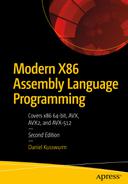
Example Ch05_03
Stack layout and argument registers at entry to CalcDistance_
Scalar Floating-Point Compares and Conversions
Any function that carries out basic floating-point arithmetic is also likely to perform floating-point compare operations and conversions between integer and floating-point values. The sample source code of this section illustrates how to perform scalar floating-point compares and data conversions. It begins with a couple of examples that demonstrate methods for comparing two floating-point values and making a logical decision based on the result. This is followed by an example that shows floating-point conversion operations using values of different types.
Floating-Point Compares
Example Ch05_04
Status Flags Set by the vcomis[d|s] Instructions
Condition | RFLAGS.ZF | RFLAGS.PF | RFLAGS.CF |
|---|---|---|---|
XMM0 > XMM1 | 0 | 0 | 0 |
XMM0 == XMM1 | 1 | 0 | 0 |
XMM0 < XMM1 | 0 | 0 | 1 |
Unordered | 1 | 1 | 1 |
Condition Codes Following Execution of vcomis[d|s]
Relational Operator | Condition Code | RFLAGS Test Condition |
|---|---|---|
XMM0 < XMM1 | Below (b) | CF == 1 |
XMM0 <= XMM1 | Below or equal (be) | CF == 1 || ZF == 1 |
XMM0 == XMM1 | Equal (e or z) | ZF == 1 |
XMM0 != XMM1 | Not Equal (ne or nz) | ZF == 0 |
XMM0 > XMM1 | Above (a) | CF == 0 && ZF == 0 |
XMM0 >= XMM1 | Above or Equal (ae) | CF == 0 |
Unordered | Parity (p) | PF == 1 |
It should be noted that the status flags shown in Table 5-1 are set only if floating-point exceptions are masked (the default state for Visual C++) and neither vcomis[d|s] operand is a QNaN, SNaN, or denormal. If floating-point invalid operation or denormal exceptions are unmasked (MXCSR.IM = 0 or MXCSR.DM = 0) and one of the compare operands is a QNaN, SNaN, or denormal, the processor will generate an exception without updating the status flags in RFLAGS. Chapter 4 contains additional information regarding use of the MXCSR register, QNaNs, SNaNs, and denormals.
Example Ch05_05
Similar to the previous example, the C++ code for example Ch05_05 contains some test cases that exercise the assembly language function CompareVCMPSD_. Following the C++ code in Listing 5-5 is the assembly language header file cmpequ.asmh. This file contains a collection of equate directives, which are used to assign symbolic names to numeric values. The equate directives in cmpequ.asmh define symbolic names for the compare predicates that are used by a number of x86-AVX scalar and packed compare instructions including vcmpsd. You’ll shortly see how this works. There is no standard file extension for an x86 assembly language header file; I use .asmh but .inc is also frequently used.
Using an assembly language header file is similar to using a C++ header file. In the current example, the statement include <cmpequ.asmh> incorporates the contents of cmpequ.asmh into the file Ch05_05_.asm during assembly. The angled brackets surrounding the filename can be omitted if the filename doesn’t contain any backslashes or MASM special characters, but it’s usually simpler and more consistent to just always use them. Besides equate statements, assembly language header files are often used for macro definitions. You’ll learn about macros later in this chapter.
Many x86 assemblers including MASM support pseudo-op forms of the vcmpsd instruction and its single-precision counterpart vcmpss. Pseudo-ops are simulated instruction mnemonics with the compare predicate embedded within the mnemonic text. In function CompareVCMPSD_, for example, the pseudo-op vcmpeqsd xmm2,xmm0,xmm1 could have been used instead of the instruction vcmpsd xmm2,xmm0,xmm1,CMP_EQ. Personally, I find the standard reference manual mnemonics easier to read since the compare predicate is explicitly specified as an operand instead being buried within the pseudo-op, especially when using one of the more esoteric compare predicates.
In this section, you learned how to perform compare operations using the vcomi[d|s] and vcmps[d|s] instructions. You might be wondering at this point which compare instructions should be used. For basic scalar floating-point compare operations (e.g., equal, not equal, less than, less than or equal, greater than, and greater than or equal), the vcomis[d|s] instructions are slightly simpler to use since they directly set the status flags in RFLAGS. The vcmps[d|s] instructions must be used to take advantage of the extended compare predicates that AVX supports. Another reason for using the vcmps[d|s] instructions is the similarity between these instructions and the corresponding vcmpp[d|s] instructions for packed floating-point operands. You’ll learn how to use the packed floating-point compare instructions in Chapter 6.
Floating-Point Conversions
Example Ch05_06
Near the top of the C++ code is a declaration for union Uval, which is used for data exchange purposes. This is followed by two enumerations: one to select a floating-point conversion type (CvtOp) and another to specify a floating-point rounding mode (RoundingMode). The C++ function main initializes a couple of Uval instances as test cases and invokes the assembly language function ConvertScalar_ to perform various conversions using different rounding modes. The result of each conversion operation is then displayed for verification and comparison purposes.
The AVX floating-point rounding mode is determined by the rounding control field (bits 14 and 13) of the MXCSR register, as discussed in Chapter 4. The default rounding mode for Visual C++ programs is round to nearest. According to the Visual C++ calling convention, the values in MXCSR[15:6] (i.e., MXCSR register bits 15 through 6) must be preserved across most function boundaries. The code in main fulfills this requirement by calling the function GetMxcsrRoundingMode_ to save the current rounding mode prior to performing any conversion operations using ConvertScalar_. The original rounding mode is ultimately restored using the function SetMxcsrRoundingMode_. Note that the original rounding mode is restored prior to the cout statements in main. Also note that I’ve simplified the rounding mode save and restore code somewhat by not preserving the rounding mode prior to each use ConvertScalar_ and restoring it immediately afterward.
Listing 5-6 also shows the rounding mode control functions. The function GetMxcsrRoundingMode_ uses a vstmxcsr dword ptr [rsp+8] instruction (Store MXCSR RegisterState) to save the contents of MXCSR to the RCX home area on the stack. Recall that a function can use its home area on the stack for any transient storage purpose. The sole operand of the vstmxcsr instruction must be a doubleword in memory; it cannot be a general-purpose register. The ensuing mov eax,[rsp+8] instruction copies the current MXCSR value into register EAX. This is followed a shift and bitwise AND operation that extracts the rounding control bits. The corresponding SetMxcsrRoundingMode_ function uses the vldmxcsr instruction (Load MXCSR Register) to set a rounding mode. The vldmxcsr instruction also requires its sole operand to be a doubleword in memory. Note that the function SetMxcsrRoundingMode_ also uses the vstmxcsr instruction and some masking operations to ensure that only the MXCSR’s rounding control bits are modified when setting a new rounding mode .
The function ConvertScalar_ performs floating-point conversions using the specified numerical arguments and conversion operator. Following validation of the argument cvt_op, a jmp [CvtOpTable+rax*8] instruction transfers control to the appropriate section in the code that performs the actual conversion. Note that this instruction exploits a jump table. Here, register RAX (which contains cvt_op) specifies an index into the table CvtOpTable. The table CvtOpTable is defined immediately after the ret instruction and contains offsets to the various conversion code blocks. You’ll learn more about jump tables in Chapter 6.
It is also important to note that the same instruction mnemonic is sometimes used when converting an integer to floating-point and vice versa. For example, the instruction vcvtsi2ss xmm0,xmm0,eax (located near the label I32_F32) converts a 32-bit signed integer to single-precision floating-point, and the instruction vcvtsi2ss xmm0,xmm0,rax (located near the label I64_F32) converts a 64-bit signed integer to single-precision floating-point.
Scalar Floating-Point Arrays and Matrices
In Chapter 3 you learned how to access individual elements and carry out calculations using integer arrays and matrices. In this section, you learn how to perform similar operations using floating-point array and matrices. As you’ll soon see, the same assembly language coding techniques are often used for both integer and floating-point arrays and matrices.
Floating-Point Arrays
Example Ch05_07


The C++ code for example Ch05_07 is straightforward. It includes a function named CalcMeanStdevCpp that calculates the sample mean and sample standard deviation of an array of double-precision floating-point values. Note that this function and its assembly language equivalent return the calculated mean and standard deviation using pointers. The remaining C++ code initializes a test array and exercises both calculating functions.
Upon entry to the assembly language function CalcMeanStdev_, the number of array elements n is checked for validity. Note that the number of array elements must be greater than one in order to calculate a sample standard deviation. Following validation of n, the vxorpd,xmm0,xmm0,xmm0 instruction (Bitwise XOR of Packed Double-Precision Floating-Point Values) initializes sum to 0.0. This instruction performs a bitwise XOR operation using all 128 bits of both source operands. A vxorpd instruction is used here to initialize sum to 0.0 since AVX does not include an explicit XOR instruction for scalar floating-point operands.
The code block that calculates the sample mean requires only seven instructions. The first instruction of the summing loop, vaddsd xmm0,xmm0,real8 ptr [r8+rax*8], adds x[i] to sum. The inc eax instruction that follows updates i and the summing loop repeats until i reaches n. Following the summing loop, the instruction vcvtsi2sd xmm1,xmm1,r9d promotes a copy of n to double-precision floating-point, and the ensuing vdivsd xmm3,xmm0,xmm1 instruction calculates the final sample mean. The mean is then saved to the memory location pointed to by RCX.
Floating-Point Matrices
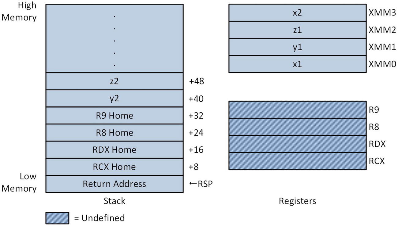
Example Ch05_08
The C++ source code that’s shown in Listing 5-8 is similar to what you saw in Chapter 3. The techniques used to calculate the matrix element offsets are identical. The biggest modification made to the C++ code was changing the appropriate matrix type declarations from int to float. Another difference between this example and the one you saw in Chapter 3 is the addition of the argument offset to the declarations of CalcMatrixSquaresF32Cpp and CalcMatrixSquaresF32_. Both of these functions now calculate y[i][j] = x[j][i] * x[j][i] + offset.
Stack layout and argument registers after execution of push rdi in CalcMatrixSquaresF32_
Based on the source code examples in this section , it should be readily apparent that when working with arrays or matrices, techniques independent of the actual data type can be employed to reference specific elements. For-loop constructs can also be coded using methods that are detached from the actual data type.
Calling Convention
The sample source code presented thus far in this book has informally discussed various aspects of the Visual C++ calling convention. In this section, the calling convention is formally explained. It reiterates some earlier elucidations and also introduces new requirements and features that haven’t been discussed. A basic understanding of the calling convention is necessary since it’s used extensively in the sample code of subsequent chapters. As a reminder, if you’re reading this book to learn x86-64 assembly language programming and plan on using it with a different operating system or high-level language, you should consult the appropriate documentation for information regarding the particulars of that calling convention.
Visual C++ 64-Bit Volatile and Non-Volatile Registers
Register Group | Volatile Registers | Non-Volatile Registers |
|---|---|---|
General-purpose | RAX, RCX, RDX, R8, R9, R10, R11 | RBX, RSI, RDI, RBP, RSP, R12, R13, R14, R15 |
XMM | XMM0 – XMM5 | XMM6 – XMM15 |
On systems that support AVX or AVX2, the high-order 128 bits of each YMM register are classified as volatile. Similarly, the high-order 384 bits of registers ZMM0–ZMM15 are classified as volatile on systems that support AVX-512. Registers ZMM16–ZMM31 and the corresponding YMM and XMM registers are also designated as volatile and need not be preserved. 64-bit Visual C++ programs normally don’t use the x87 FPU. Assembly language functions that use this resource are not required to preserve the contents of the x87 FPU register stack, which means that the entire register stack is classified as volatile.
Do not call any other functions.
Do not modify the contents of the RSP register.
Do not allocate any local stack space.
Do not modify any of the non-volatile general-purpose or XMM registers .
Do not use exception handling.
64-bit assembly language leaf functions are easier to code, but they’re only suitable for relatively simple computational tasks. A non-leaf function can use the entire x86-64 register set, create a stack frame , allocate local stack space, or call other functions provided it complies with the calling convention’s precise requirements for prologs and epilogs. The sample code of this section exemplifies these requirements.
In the remainder of this section, you’ll examine four source code examples. The first three examples illustrate how to code non-leaf functions using explicit instructions and assembler directives. These programs also convey critical programming information regarding the organization of a non-leaf function stack frame. The fourth example demonstrates how to use several prolog and epilog macros . These macros help automate most of the programming labor that’s associated with non-leaf functions.
Basic Stack Frames
Example Ch05_09
The purpose of the C++ code in Listing 5-9 is to initialize a test case for the assembly language function Cc1_. This function calculates and returns the sum of its eight signed-integer argument values. The results are then displayed using a series stream writes to cout.
In the assembly language code, the Cc1_ proc fame statement marks the beginning of function Cc1_. The frame attribute notifies the assembler that the function Cc1_ uses a stack frame pointer. It also instructs the assembler to generate static table data that the Visual C++ runtime environment uses to process exceptions. The ensuing push rbp instruction saves the caller’s RBP register on the stack since function Cc1_ uses this register as its stack frame pointer. The .pushreg rbp statement that follows is an assembler directive that saves offset information about the push rbp instruction in the exception handling tables. Keep in mind that assembler directives are not executable instructions; they are directions to the assembler on how to perform specific actions during assembly of the source code.
A sub rsp,16 instruction allocates 16 bytes of stack space for local variables. The function Cc1_ only uses eight bytes of this space, but the Visual C++ calling convention requires non-leaf functions to maintain 16-byte alignment of the stack pointer outside of the prolog. You’ll learn more about stack pointer alignment requirements later in this section. The next statement, .allocstack 16, is an assembler directive that saves local stack size allocation information in the runtime exception handling tables.
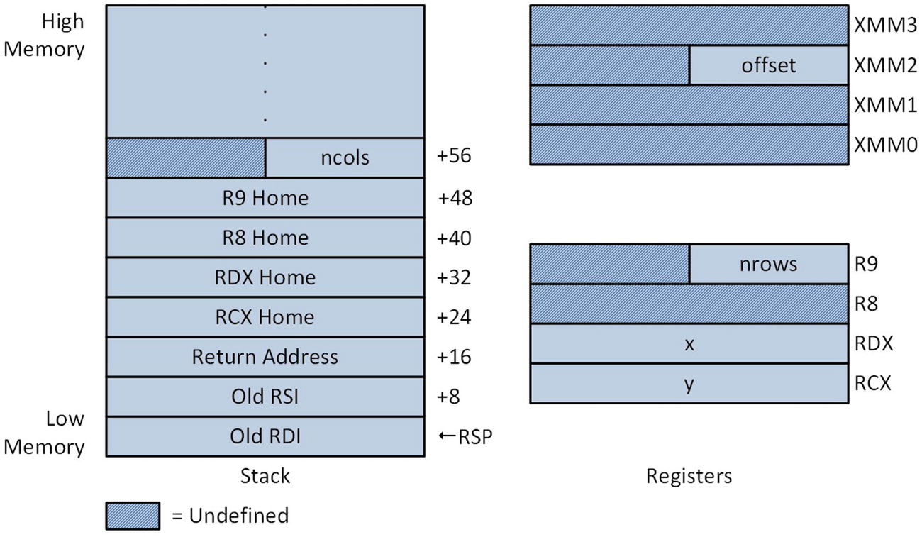
Stack layout and argument registers of function Cc1_ following completion of prolog
The RBP_RA = 24 statement is a directive similar to an equate that assigns the value 24 to the symbol named RBP_RA. This represents the extra offset bytes (compared to a standard leaf function ) needed to correctly reference the home area of Cc1_, as shown in Figure 5-3. The next block of instructions saves registers RCX, RDX, R8, and R9 to their respective home areas on this stack. This step is optional and included in Cc1_ for illustrative purposes. Note that the offset of each mov instruction includes the symbolic constant RBP_RA. Another option allowed by the Visual C++ calling convention is to save an argument register to its corresponding home area prior to the push rbp instruction using RSP as a base register (e.g., mov [rsp+8],rcx, mov [rsp+16],rdx, and so on). Also keep in mind that a function can use its home area to store other temporary values. When used for alternative storage purposes, the home area should not be referenced by an assembly language instruction until after the .endprolog directive .
Following the home area save operation, the function Cc1_ sums argument values a, b, c, and d. It then saves this intermediate sum to LocalVar1 on the stack using a mov [rbp],r8 instruction. Note that the summation calculation sign-extends argument values a, b, and c using a movsx or movsxd instruction. A similar sequence of instructions is used to sum argument values e, f, g, and h, which are located on the stack and referenced using the stack frame pointer RBP and a constant offset. The symbolic constant RBP_RA is also used here to account for the extra stack space needed to reference argument values on the stack. The two intermediate sums are then added to produce the final result in register RAX.
Using Non-Volatile General-Purpose Registers
Example Ch05_10
Similar to the previous example of this section, the purpose of the code C++ in Listing 5-10 is to prepare a simple test case in order to exercise the assembly language function Cc2_. In this example, the function Cc2_ calculates the sums and products of two 64-bit signed integer arrays. The results are then streamed to cout.
Toward the top of the assembly language code is a series of named constants that control how much stack space is allocated in the prolog of function Cc2_. Like the previous example, the function Cc2_ includes the frame attribute as part of its proc statement to indicate that it uses a stack frame pointer. A series of push instructions saves non-volatile registers RBP, RBX, R12, and R13 on the stack. Note that a .pushreg directive is used following each push instruction, which instructs the assembler to add information about each push instruction to the Visual C++ runtime exception handling tables .
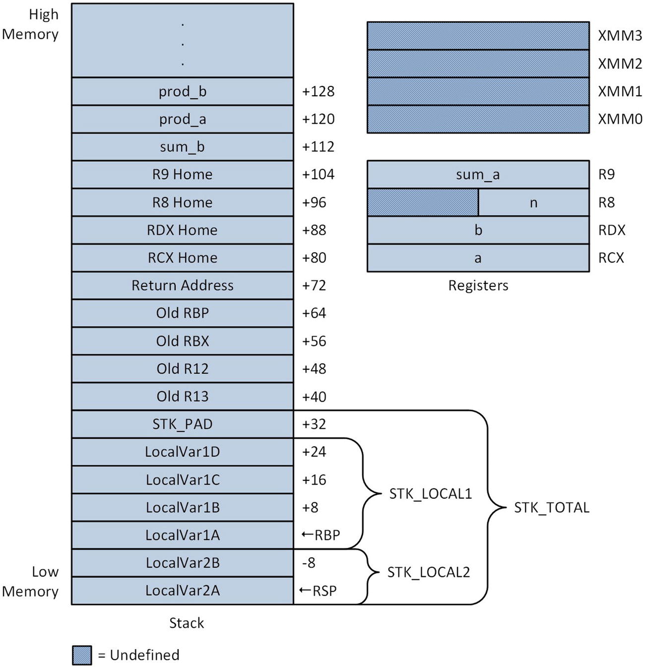
Stack layout and argument registers following execution of the lea rbp,[rsp+STK_LOCAL2] instruction in function Cc2_
The next code block contains instructions that initialize the local variables on the stack . These instructions are for demonstration purposes only. Note that this block uses a vmovdqa [rbp-16],xmm5 instruction (Move Aligned Packed Integer Values), which requires its destination operand to be aligned on a 16-byte boundary. This instruction embodies the calling convention’s mandatory alignment of the RSP register to a 16-byte boundary. Following initialization of the local variables, the argument registers are saved to their home locations, also merely for demonstration purposes.
The logic of the main processing loop is straightforward. Following validation of argument value n, the function Cc2_ initializes the intermediate values sum_a (R10) and sum_b (R11) to 0, and prod_a (R12) and prod_b (R13) to 1. It then calculates the sum and product of the input arrays a and b. The final results are saved to the memory locations specified by the caller. Note that the pointers for sum_b, prod_a, and prod_b were passed to Cc2_ using the stack.
Using Non-Volatile XMM Registers
Example Ch05_11


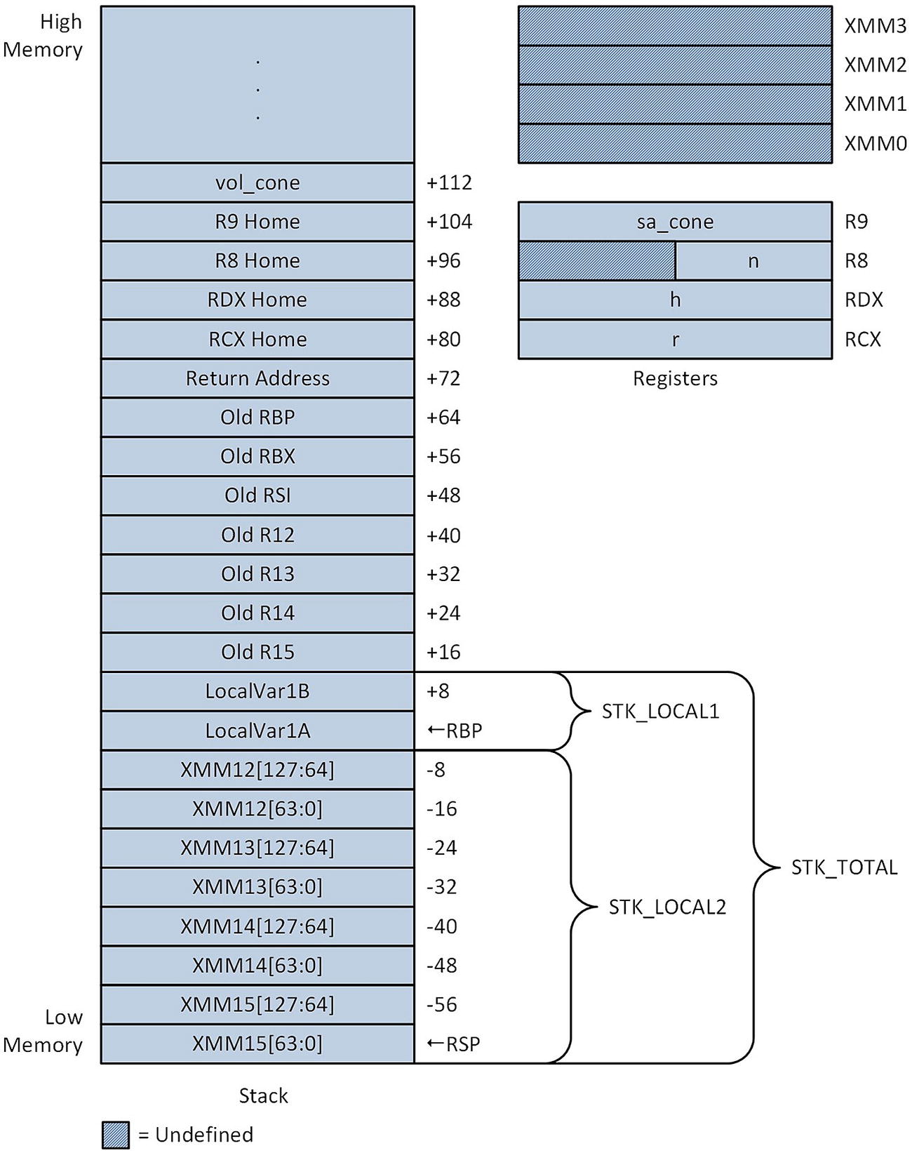
Stack layout and argument registers following execution of the vmovdqa xmmword ptr [rbp-STK_LOCAL2],xmm15 instruction in function Cc3_
Following the prolog, local variables LocalVar1A and LocalVar1B are accessed for demonstration purposes only. Initialization of the registers used by the main processing loop occurs next. Note that many of these initializations are either suboptimal or superfluous; they are performed merely to elucidate use of the non-volatile and general-purpose and XMM registers. Calculation of the cone surface areas and volumes is then carried out using AVX double-precision floating-point arithmetic.
Macros for Prologs and Epilogs
The purpose of the previous three source code examples was to elucidate use of the Visual C++ calling convention for 64-bit non-leaf functions . The calling convention’s rigid requirements for function prologs and epilogs are somewhat lengthy and a potential source of programming errors. It is important to recognize that the stack layout of a non-leaf function is primarily determined by the number of non-volatile (both general-purpose and XMM) registers that must be preserved and the amount of local stack storage space that’s needed. A method is needed to automate most of the coding drudgery associated with the calling convention.
Example Ch05_12
Body Surface Area Equations
Formula | Equation |
|---|---|
DuBois and DuBois | BSA = 0.007184 × H 0.725 × W 0.425 |
Gehan and George | BSA = 0.0235 × H 0.42246 × W 0.51456 |
Mosteller |
|

The assembly language code for example Ch05_12 begins with an include statement that incorporates the contents of the file MacrosX86-64-AVX.asmh. This file (source code not shown but included with the Chapter 5 download package) contains a number of macros that help automate much of the coding grunt work that’s associated with the Visual C++ calling convention. A macro is an assembler text substitution mechanism that enables a programmer to represent a sequence of assembly language instructions, data definitions, or other statements using a single text string. Assembly language macros are typically employed to generate sequences of instructions that will be used more than once. Macros are also frequently used to avoid the performance overhead of a function call. Source code example Ch05_12 demonstrates the use of the calling convention macros. You learn how to define your own macros later in this book.
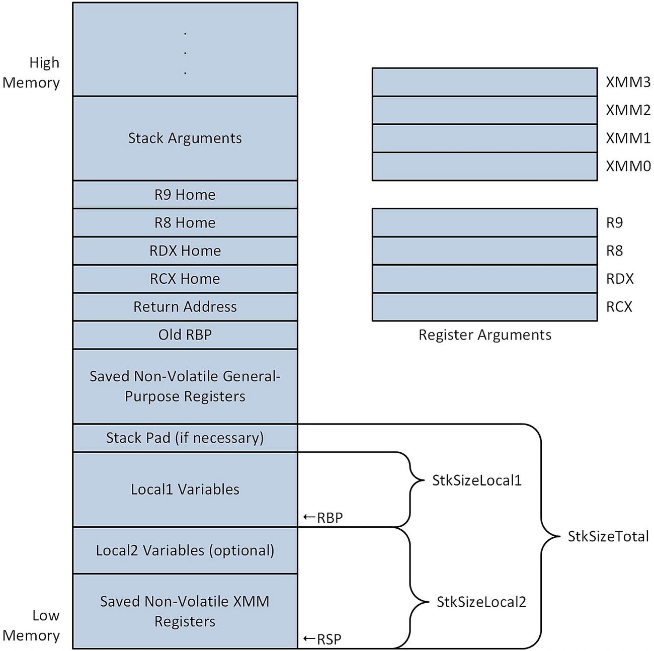
Generic stack layout for a non-leaf function
Returning to the assembly code , immediately after the include statement is a .const section that contains definitions for the various floating-point constant values used in the BSA equations. The line extern pow:proc enables use of the external C++ library function pow. Following the Cc4_ proc frame statement , the macro _CreateFrame is used to generate the code that initializes the function’s stack frame . It also saves the specified non-volatile general-purpose registers on the stack. The macro requires several additional parameters, including a prefix string and the size in bytes of StkSizeLocal1 and StkSizeLocal2 (see Figure 5-6). The macro _CreateFrame uses the specified prefix string to create symbolic names that can be employed to reference items on the stack. It’s somewhat convenient to use a shortened version of the function name as the prefix string but any unique text string can be used. Both StkSizeLocal1 and StkSizeLocal2 must be evenly divisible by 16. StkSizeLocal2 must also be less than or equal to 240, and greater than or equal to the number of saved XMM registers multiplied by 16.
The next statement uses the _SaveXmmRegs macro to save the specified non-volatile XMM registers to the XMM save area on the stack. This is followed by the _EndProlog macro, which signifies the end of the function’s prolog. Subsequent to the completion of the prolog, register RBP is configured as the function’s stack frame pointer. It is also safe to use any of the saved non-volatile general-purpose or XMM registers subsequent to the _EndProlog macro.
The block of instructions that follows _EndProlog saves the argument registers to their home locations on the stack. Note that each mov instruction includes a symbolic name that equates to the offset of the register’s home area on the stack relative to the RBP register. The symbolic names and the corresponding offset values were automatically generated by the _CreateFrame macro. The home area can also be used to store temporary data instead of the argument registers, as mentioned earlier in this chapter.
Initialization of the processing loop variables occurs next. The value n in register R8D is checked for validity and saved on the stack as a local variable. Several non-volatile registers are then initialized as pointer registers. Non-volatile registers are used in order to avoid register reloads following each call to the C++ library function pow. Note that the pointer to array bsa2 is loaded from the stack using a mov r15,[rbp+Cc4_OffsetStackArgs] instruction. The symbolic constant Cc4_OffsetStackArgs also was automatically generated by the macro _CreateFrame and equates to the offset of the first stack argument relative to the RBP register. A mov rbx,[rbp+Cc4_OffsetStackArgs+8] instruction loads argument bsa3 into register RBX; the constant 8 is included as part of the source operand displacement since bsa3 is the second argument passed via the stack.
The Visual C++ calling convention requires the caller of a function to allocate that function’s home area on the stack. The sub rsp,32 instruction performs this operation. The ensuing block of code calculates the BSA values using the equations shown in Table 5-4. Note that registers XMM0 and XMM1 are loaded with the necessary argument values prior to each call to pow. Also note that some of the return values from pow are preserved in non-volatile XMM registers prior to their actual use.
Summary
The vadds[d|s], vsubs[d|s], vmuls[d|s], vdivs[d|s], and vsqrts[d|s] instructions perform basic double-precision and single-precision floating-point arithmetic.
The vmovs[d|s] instructions copy a scalar floating-point value from one XMM register to another; they are also used to load/store scalar floating-point values from/to memory.
The vcoms[d|s] instructions compare two scalar floating-point values and set the status flags in RFLAGS to signify the result.
The vcmps[d|s] instructions compare two scalar floating-point values using a compare predicate. If the compare predicate is true, the destination operand is set to all ones; otherwise, it is set to all zeros.
The vcvts[d|s]2si instructions convert a scalar floating-point value to a signed integer value; the vcvtsi2s[d|s] instructions perform the opposite conversion.
The vcvtsd2ss instruction converts a scalar double-precision floating-point value to single-precision; the vcvtss2sd instruction performs the opposite conversion.
The vldmxcsr instruction loads a value into the MXCSR register; the vstmxcsr instruction saves the current contents of the MXCSR register.
Leaf functions can be used for simple processing tasks and do not require a prolog or epilog. A non-leaf function must use a prolog and epilog to save and restore non-volatile registers, initialize a stack frame pointer, allocate local storage space on the stack, or call other functions.