Table of Contents for
Learn Robotics with Raspberry Pi
 Learn Robotics with Raspberry Pi
Published by
No Starch Press, 2018
Learn Robotics with Raspberry Pi
Published by
No Starch Press, 2018
- Cover Page
- Title Page
- Copyright Page
- Dedication
- CONTENTS
- CONTENTS IN DETAIL
- ACKNOWLEDGMENTS
- FOREWORD
- INTRODUCTION
- CHAPTER 1: GETTING UP AND RUNNING
- CHAPTER 2: ELECTRONICS BASICS
- CHAPTER 3: BUILDING YOUR ROBOT
- CHAPTER 4: MAKING YOUR ROBOT MOVE
- CHAPTER 5: AVOIDING OBSTACLES
- CHAPTER 6: CUSTOMIZING WITH LIGHTS AND SOUND
- CHAPTER 7: LINE FOLLOWING
- CHAPTER 8: COMPUTER VISION: FOLLOW A COLORED BALL
- NEXT STEPS
- RASPBERRY PI GPIO DIAGRAM
- RESISTOR GUIDE
- HOW TO SOLDER
- RUN PROGRAM ON STARTUP
- Learn Robotics with Raspberry Pi®: Build and Code Your Own Moving, Sensing, Thinking Robots
- Learn Robotics with Raspberry Pi®: Build and Code Your Own Moving, Sensing, Thinking Robots
6
CUSTOMIZING WITH LIGHTS AND SOUND
MAKING YOUR ROBOT STAND OUT FROM THE CROWD CAN BE A WHOLE LOT OF FUN. IN THIS CHAPTER, I’LL SHOW YOU HOW TO ADD LIGHTS AND SPEAKERS TO YOUR ROBOT TO MAKE IT FLASHIER, LOUDER, AND MORE EXCITING. AS USUAL, WE’LL COVER THE THEORY, THE PARTS YOU’LL NEED, AND HOW TO USE THEM.
ADDING NEOPIXELS TO YOUR RASPBERRY PI ROBOT
One of the best ways to grab attention is to have your robot put on a light show. With the right code and wiring and the help of some bright and colorful LEDs, you can make dazzling spectacles as your robot scuttles around the floor!
In this project you’ll outfit your robot with a string of super-bright, multicolor LEDs. I’ll guide you through getting the components, wiring them up, and programming different patterns. We’ll combine these new additions with the Wiimote program from Chapter 4 so that you can trigger different LED combinations by pressing the Wiimote’s buttons.
Introducing NeoPixels and the RGB Color System
At the start of this book, I introduced LEDs and showed you how to wire up a single-color LED to your Raspberry Pi and flash it on and off using a simple Python script.
That was a great project to get you started, but a lonely LED is hardly going to create the desired wow factor for your robot. Instead, for this project, we’ll use NeoPixels like the ones shown in Figure 6-1.
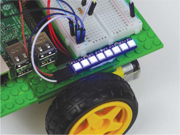
FIGURE 6-1 NeoPixels on my robot
NeoPixels are a range of affordable, ultra-bright RGB LEDs from the open source hardware company Adafruit. RGB, which stands for red green blue, is a system of color mixing that computers use to represent a massive spectrum of colors. Red, green, and blue light can be combined in various proportions to produce any color in the visible light spectrum, from orange to indigo to green! By setting the levels of R, G, and B each in a range of 0 to 100 percent intensity, you can create new colors. For example, pure red is represented by 100% R, 0% G, and 0% B, and purple is 50% R, 0% G, and 50% B.
Instead of percentages, computers normally represent the levels of each color as a range of decimal numbers from 0 to 255 (256 levels). So, for red the combination is 255 R, 0 G, and 0 B. See Figure 6-2 for the full RGB range represented as a color wheel.
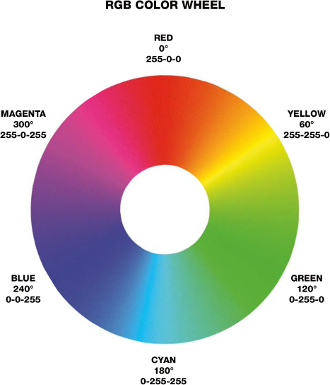
FIGURE 6-2 The full RGB range represented as a color wheel
This means that, unlike the single-color LED, each RGB NeoPixel can display a huge range of colors. You can calculate the exact range by multiplying the number of possibilities for each level: 256 × 256 × 256 = 16,777,216. That’s almost 17 million different colors!
But how can a single LED represent so many colors? Well, if you look closely at the NeoPixel in Figure 6-3, you’ll see that there are three distinct areas. This is because each NeoPixel actually comprises three LEDs: one each of red, green, and blue. You combine these colors in varying quantities, as discussed earlier, to produce an RGB color.
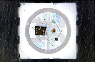
FIGURE 6-3 A macro shot of a NeoPixel
The Parts List
NeoPixels can be used individually or chained together, and Adafruit has a huge range of NeoPixel products available in many different forms and sizes—from individual pixels to huge matrices made out of hundreds of NeoPixels.
In this project I recommend picking up a NeoPixel Stick—this is a roughly 2-inch-long LED arrangement of eight NeoPixels, as shown in Figure 6-4. Its combination of small size and bright output makes it ideal for your robot.
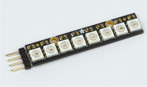
FIGURE 6-4 NeoPixel Stick with headers soldered on
If you’re in the United States, you can buy one of these from Adafruit’s website for less than $6. If you’re elsewhere in the world, just search the net for “NeoPixel Stick,” and you should have no trouble finding one for a similar price from another retailer.
It is worth noting that the NeoPixel Stick does require a small degree of assembly: you will have to solder a set of male headers onto the power and Data-In pads, as shown in Figure 6-5. There are two sets of pads on the back that look almost identical, except one side is for input into the Stick, and the other for output from the Stick. This is so you can chain the output of one Stick into the input of another Stick to join several together. We will only use one NeoPixel Stick in this project, but you may want to experiment with more NeoPixels at a later point.
You’ll have to purchase some male headers separately (which cost less than $1) and solder them to the set of the terminal pads that includes the DIN (Data-In) pin.
If you have never soldered before, check out “How to Solder” on page 204 for guidance.
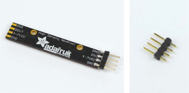
FIGURE 6-5 The back of my NeoPixel Stick with headers soldered to the input side (L); an individual four-pin header (R)
Other than the NeoPixel Stick and headers, you’ll only need a few jumper wires to connect the NeoPixels, as well as some sticky tack to affix them to your Raspberry Pi robot.
Wiring Up Your NeoPixel Stick
Once you have a freshly soldered NeoPixel Stick, you can wire it up to your Pi. In total, only three connections are required to get it working. Remember that I won’t show the previous connections in the diagrams, but you don’t need to disconnect any of your previous projects to follow along with this one.
Like the HC-SR04 in the previous chapter, the Stick can be plugged directly into a breadboard, but as with that project, I don’t recommend doing so here. Instead, it’s better to connect the Stick using jumper wires so you can mount it elsewhere on your robot.
- Use a jumper wire to connect the 4-7VDC pin of your NeoPixel Stick to the +5 V rail of your breadboard. Note that because these LEDs are extra bright, they draw a significant amount of current. Consequently, when we run the software later, you’ll need to connect and switch on the robot’s batteries.
- Next, use another jumper wire to attach one of the GND pins of your Stick to the common ground rail of your breadboard. This grounds your NeoPixels to both the power supply (your batteries) and the Raspberry Pi. Check out Figure 6-6 for a diagram of what your setup should look like so far.
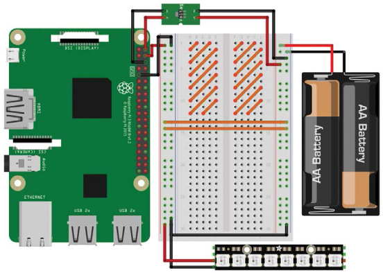
FIGURE 6-6 Adafruit NeoPixel Stick connected to +5 V and ground
- Use a final jumper wire to connect the DIN (Data-In) pin of your NeoPixel Stick to physical pin 19 (BCM 10) on your Raspberry Pi (see “Raspberry Pi GPIO Diagram” on page 200 for a guide to pin numbering). The complete circuit should look like Figure 6-7.
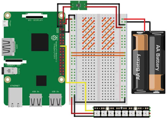
FIGURE 6-7 Complete breadboard diagram with the NeoPixel Stick wired up to power and your Pi
Use sticky tack to mount your NeoPixels somewhere on your robot. I’ve mounted mine to the right of the breadboard.
Installing the Software
Before you program your NeoPixel Stick, you must first install and configure the necessary software. The Python library we’ll use is called rpi_ws281x, and you can download it from the internet for Python 3 using pip, a command line tool that allows you to quickly and easily install and manage Python software.
Before you proceed, you’ll need to ensure that you have pip installed for Python 3. To do so, boot up your Raspberry Pi and log in via SSH. Then, enter the following command into the terminal:
pi@raspberrypi:~ $ sudo apt-get update
This command doesn’t actually install new software; instead, it updates the list of available software your Raspberry Pi can download. After this process has completed, you can install pip for Python 3 with this command:
pi@raspberrypi:~ $ sudo apt-get install python3-pip
Most likely, you’ll be informed that pip is already installed for Python 3, in which case you’re ready to use it. If not, go through the installation process.
After this, you can install the rpi_ws281x library with one simple command:
pi@raspberrypi:~ $ sudo pip3 install rpi_ws281x
We will use the SPI bus to control the NeoPixels. This is just an electronics interface (the serial peripheral interface, to be exact) on select GPIO pins of every Raspberry Pi. By default, SPI is disabled, but you should have enabled it in the GUI when you set up your Pi at the start of this book. You can check that you have it enabled by opening the Raspberry Pi software configuration tool with this command:
pi@raspberrypi:~ $ sudo raspi-config
Once the tool opens, scroll down to Interfacing Options, select it, and then press ENTER. You’ll be presented with the menu in Figure 6-8.
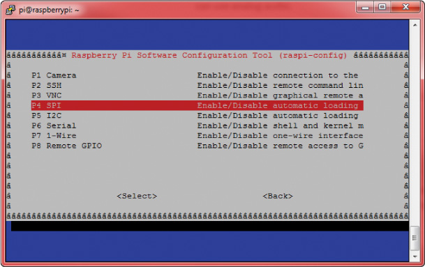
FIGURE 6-8 The Interfacing Options menu of the raspi-config tool
Scroll down and select SPI. You’ll then be asked whether you would like the SPI interface to be enabled. Use the left/right arrow keys to highlight Yes. After you’ve done so, you’ll return to the main raspi-config menu. You can exit the configuration tool by pressing the right arrow key twice (highlighting Finish) and then pressing ENTER. Now reboot your Raspberry Pi using this command:
pi@raspberrypi:~ $ sudo reboot
Now SPI is enabled!
MAKING SPI WORK CORRECTLY ON PI 3
If you’re using the Raspberry Pi 3 Model B/B+ there is one more step you’ll have to take before moving on. You don’t have to worry about this step if you’re using an older Pi.
To get SPI to work correctly on a Pi 3, you’ll have to change the GPU core frequency to 250 MHz. All this means is that you are changing the graphics unit on your Raspberry Pi 3 to run at a slightly different rate. If you don’t do this, your NeoPixels may behave erratically and not display the correct patterns.
To make this change, enter the following command into the terminal:
pi@raspberrypi:~ $ sudo nano /boot/config.txt
This will open up a configuration file containing various text and options. Scroll down to the bottom of this file and, on a new line, add this text:
core_freq=250
So, for example, the end of my configuration file looks like this:
--snip--
# Additional overlays and parameters are documented /boot/
overlays/README
# Enable audio (loads snd_bcm2835)
dtparam=audio=on
start_x=1
gpu_mem=128
core_freq=250
Once you have added this line, save the file in Nano by pressing CTRL-X, and then press Y and ENTER. Then reboot your Raspberry Pi.
NOTE
If you think that this process may have changed, or you’re concerned that you have done this step incorrectly, check the book’s website at https://nostarch.com/raspirobots/.
Configuring the Library’s Example Code
Before we go any further, let’s test the library you just installed to make sure everything is working perfectly. If you have already downloaded the software bundle that comes with this book onto your Raspberry Pi, then you already have the test file, strandtest.py. This program has been written by Adafruit to test out NeoPixels. If you don’t have it, download the example code from the internet by entering the following command:
pi@raspberrypi:~/robot $ wget https://raw.githubusercontent.com/
the-raspberry-pi-guy/raspirobots/master/strandtest.py
After this has finished, you will have the exact same test code that is provided in the software bundle.
Before running the example code, we need to change a few settings. To look at the code and the current settings, open the example code file using Nano as follows:
pi@raspberrypi:~/robot $ nano strandtest.py
The purpose of this program is run through several example light patterns. The code is quite long and full of functions that define the different sequences, but you don’t need to edit any of this code.
You will, however, need to edit some of the constants inside the program. Near the start of the code you’ll find the chunk of code to be edited, which is reproduced in Listing 6-1.
# LED strip configuration:
➊ LED_COUNT = 16 # Number of LED pixels.
➋ LED_PIN = 18 # GPIO pin connected to the pixels 
(18 uses PWM!).
➌ #LED_PIN = 10 # GPIO pin connected to the pixels
(10 uses SPI /dev/spidev0.0).
LED_FREQ_HZ = 800000 # LED signal frequency in hertz (usually
800khz)
LED_DMA = 10 # DMA channel to use for generating
signal (try 10)
LED_BRIGHTNESS = 255 # Set to 0 for darkest and 255 for
brightest
LED_INVERT = False # True to invert the signal (when using
NPN transistor level shift)
LED_CHANNEL = 0 # set to '1' for GPIOs 13, 19, 41, 45
or 53
LED_STRIP = ws.WS2811_STRIP_GRB # Strip type and color
ordering
LISTING 6-1 LED strip configuration of strandtest.py
The words after each hash character (#) are comments. Programmers will often put comments in their code as a form of annotation. Comments help human readers and other programmers understand what the various parts of your program do.
In Python, a comment starts with a hash character (#). When Python interprets this code, it simply ignores everything after the hash. It is good coding practice to comment your programs, especially if you are working in a team or open-sourcing your work. Commenting is also handy as a reminder to yourself if you revisit a program in the future and have forgotten how it works!
The first thing you need to change appears at ➊: LED_COUNT. This is a constant for the number of NeoPixels you have attached to your Pi. By default it is set to 16, so you need to change it to 8 instead.
Secondly, you’ll change the pin number being used. The constant LED_PIN at ➋ is set to BCM 18 by default, but your NeoPixel Stick is connected to BCM 10. The authors of this example code have noticed that using BCM 10 is a popular choice, so they’ve provided an alternative constant definition at ➌, but commented it out.
To swap these lines around, add a hash to the start of the line at ➋. This will comment out that line so that Python will ignore it. Then, remove the hash at ➌ to uncomment the line, which will make Python run the line of code assigning LED_PIN to 10.
Your final block of constants should now look like the code in Listing 6-2.
# LED strip configuration:
LED_COUNT = 8 # Number of LED pixels.
#LED_PIN = 18 # GPIO pin connected to the pixels (18
uses PWM!).
LED_PIN = 10 # GPIO pin connected to the pixels (10
uses SPI /dev/spidev0.0).
LED_FREQ_HZ = 800000 # LED signal frequency in hertz (usually
800khz)
LED_DMA = 10 # DMA channel to use for generating
signal (try 10)
LED_BRIGHTNESS = 255 # Set to 0 for darkest and 255 for
brightest
LED_INVERT = False # True to invert the signal (when using
NPN transistor level shift)
LED_CHANNEL = 0 # set to '1' for GPIOs 13, 19, 41, 45 or 53
LED_STRIP = ws.WS2811_STRIP_GRB # Strip type and color
ordering
LISTING 6-2 The new LED strip configuration of strandtest.py
Once you have your code set up, you can run it.
Running the Example Code
Save the changes you have made to the example program and run it with the following command:
pi@raspberrypi:~/robot $ python3 strandtest.py -c
And you might want to grab a pair of sunglasses! Your NeoPixels should now be going through a sequence of patterns, the names of which are displayed in the terminal as they start (see Figure 6-9).
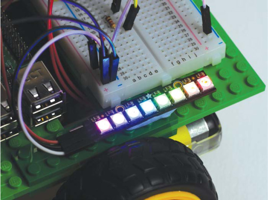
FIGURE 6-9 NeoPixels going through the strandtest.py example program
When your retinas have had enough, press CTRL-C to kill the example code. The –c you should have added to the end of your original run command should turn off your LEDs. If you didn’t add –c to the command, killing the program will just freeze your LEDs and they will remain powered on.
If you’re worried about the intensity of your LEDs and being blinded, don’t fret! As we add NeoPixel control to the Wiimote program, I’ll show you how to turn down their brightness.
Controlling NeoPixels Using the Wiimote Program
Now that you have tested out your NeoPixels and seen what they’re capable of, it’s time to add LED-controlling capabilities to the accelerometer-based Wiimote program you made earlier.
We’re going to add NeoPixels to the Wiimote program, but it would be ideal to keep a copy of the original Wiimote code without these additions just in case something goes wrong or we want to go back to it in future. To do this, we’ll create and edit a copy of the program instead. First, make sure you are in the directory where your code is stored; for me, that’s my robot directory. Then, in the terminal, copy your original Wiimote program using the command cp:
pi@raspberrypi:~/robot $ cp remote_control_accel.py neo_remote_
control.py
This command simply copies the contents of its first argument (remote_control_accel.py) to the new file specified in the second argument. As you can see, I have decided to name my NeoPixel version of the Wiimote program neo_remote_control.py. After this, open the newly copied file with Nano like so:
pi@raspberrypi:~/robot $ nano neo_remote_control.py
Now enter the modifications to the code in Listing 6-3, or you can download the complete program at https://nostarch.com/raspirobots/. I have omitted and compressed the parts of the program that have not changed.
import gpiozero
import cwiid
import time
➊ from rpi_ws281x import *
robot = gpiozero.Robot(left=(17,18), right=(27,22))
--snip--
wii.rpt_mode = cwiid.RPT_BTN | cwiid.RPT_ACC
LED_COUNT = 8
LED_PIN = 10
LED_FREQ_HZ = 800000
LED_DMA = 10
➋ LED_BRIGHTNESS = 150
LED_INVERT = False
LED_CHANNEL = 0
LED_STRIP = ws.WS2811_STRIP_GRB
➌ strip = Adafruit_NeoPixel(LED_COUNT, LED_PIN, LED_FREQ_HZ,
LED_DMA, LED_INVERT, LED_BRIGHTNESS, LED_CHANNEL, LED_STRIP)
strip.begin()
➍ def colorWipe(strip, color, wait_ms=50):
"""Wipe color across display a pixel at a time."""
➎ for i in range(strip.numPixels()):
strip.setPixelColor(i, color)
strip.show()
time.sleep(wait_ms/1000.0)
while True:
➏ buttons = wii.state["buttons"]
if (buttons & cwiid.BTN_PLUS):
colorWipe(strip, Color(255, 0, 0)) # Red wipe
if (buttons & cwiid.BTN_HOME):
colorWipe(strip, Color(0, 255, 0)) # Blue wipe
if (buttons & cwiid.BTN_MINUS):
colorWipe(strip, Color(0, 0, 255)) # Green wipe
if (buttons & cwiid.BTN_B):
colorWipe(strip, Color(0, 0, 0)) # Blank
x = (wii.state["acc"][cwiid.X] - 95) - 25
--snip--
if (turn_value < 0.3) and (turn_value > -0.3):
robot.value = (forward_value, forward_value)
else:
robot.value = (-turn_value, turn_value)
LISTING 6-3 The updated Wiimote code with NeoPixel functionality
This program relies on two additional sets of libraries that the original Wiimote code did not, so we need to import both the time and rpi_ws281x libraries ➊.
Then, just as with the original program, we set up the robot and Wiimote for use. After this, we define the same chunk of constants we saw in the example NeoPixel program. These define the various parameters for the NeoPixel Stick. Most notably, you’ll find LED_BRIGHTNESS ➋, a constant that can be set between 0 and 255. I have set mine to be dimmer and easier on the eyes at 150.
At ➌, we create the NeoPixel Stick object and set up the constants defined previously. The library is initialized on the following line.
We then define a function called colorWipe() ➍ to use later. This function has been taken directly out of the strandtest.py example. The comment inside it describes what the function does: it wipes a color across the NeoPixel Stick one pixel at a time. To do this, it takes an RGB color parameter and then uses a for loop ➎ to set each pixel to that color one by one, with a short delay in between.
After this, we start the main body of code in the infinite while loop. At the start of each loop, the status of the Wiimote buttons is read ➏. Then, depending on whether the user presses the plus, minus, or home button, a different color will wipe across the NeoPixel Stick and remain there until another button is pressed. If the user presses the B button, the NeoPixels will be reset.
The rest of the program is exactly the same as the original: it deals with the accelerometer output from the controller and makes the robot move accordingly.
Running Your Program: NeoPixels and Wiimote Control
Save your work and run your code with the following command:
pi@raspberrypi:~/robot $ python3 neo_remote_control.py
Your robot should now respond to the accelerometer data from your Wiimote. Try pressing the plus, minus, home, and B buttons to trigger the different lights, as shown in Figure 6-10.
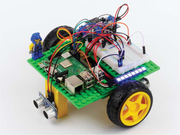
FIGURE 6-10 My robot with its NeoPixels set to blue
Before you kill the program with CTRL-C, make sure you press the B button on your Wiimote to turn the NeoPixels off!
Challenge Yourself: Experiment with Color and Pattern
Once you have played around with your robot and NeoPixels, go back into the program and the example code shown previously to see if you can set your own custom colors by changing the RGB color combinations. Or, see if you can create more adventurous light patterns to display.
If you have more than one NeoPixel Stick, you can chain them together by feeding the output of one into the input of the other to create an even more dazzling two-wheeler!
ADDING A SPEAKER TO YOUR RASPBERRY PI ROBOT
While your robot has already come a long way, one feature that has been notably absent is the ability to make noise and communicate. In the following two projects, we’ll change that! I’ll guide you through adding a small 3.5 mm speaker to your robot and using it to add sound to two previous projects: a car horn for the Wiimote program, and a parking-sensor-style beep for your obstacle avoidance program.
WARNING
You’ll only be able to follow along with these projects if you have a full-size Raspberry Pi like the Pi 3, Pi 2, Pi 1 Model B/B+ or even A+. Models such as the Pi Zero and Pi Zero W do not feature 3.5 mm audio jacks and therefore can’t easily connect to a speaker.
Understanding How 3.5 mm Speakers Work
A loudspeaker (or just plain speaker) converts an electrical audio signal into a sound that can be heard by humans. You’ll have come across many speakers in a wide range of environments—from huge speakers at concerts to the minuiscule ones inside your mobile phone.
In order to translate an electrical signal into an audible sound, speakers use an electromagnet to vibrate a cone. This cone amplifies those vibrations and pumps sound waves into the surrounding air and to your ears.
For the following two projects you’ll need a small 3.5 mm speaker, like the one shown in Figure 6-11. The 3.5 mm sizing refers to the diameter of the audio jack. This size is an industry standard, and the same as most phone headphone jacks.
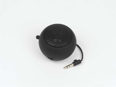
FIGURE 6-11 My small 3.5 mm speaker
NOTE
If your speaker isn’t rechargeable, the method you use to power it will depend on the exact model. If it requires USB power, you could plug it into one of your Pi’s USB ports. Having a rechargeable speaker avoids this issue and is therefore the most ideal option in this situation.
You can pick up a 3.5 mm speaker online by searching eBay, Amazon, or any regular electronics retailer. It should set you back no more than $10. The make and brand isn’t that relevant; as long as it is small enough to fit on your robot, is relatively loud, and has a 3.5 mm jack, you should be good!
Connecting Your Speaker
Most small speakers are rechargeable, so before you begin connecting your speaker to your Raspberry Pi, make sure that it is fully charged and operational.
Your Pi’s 3.5 mm audio jack is between the HDMI and Ethernet ports. Take your speaker and plug its 3.5 mm cable into the jack on your Pi, as shown in Figure 6-12.
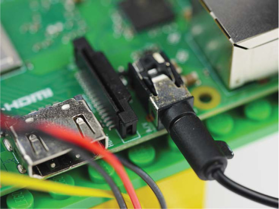
FIGURE 6-12 Speaker connected to my Raspberry Pi through the 3.5 mm audio jack
Now mount your speaker somewhere on your robot chassis. Where you mount it depends on the size of your speaker, as well as the free space that you have available. Since I didn’t have enough room to simply attach the speaker to the main chassis, I decided to create a small stalk out of a few LEGO pieces, and then affixed my speaker with sticky tack, as shown in Figure 6-13.
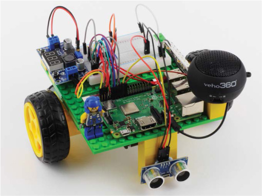
FIGURE 6-13 My 3.5 mm speaker connected to my Pi and mounted on top of a small LEGO stalk
ADDING A CAR HORN TO THE WIIMOTE PROGRAM
Now let’s extend the previous program so that your robot sounds a car horn at your command. We’ll edit the NeoPixel Wiimote program to activate a horn sound effect when the A button on your Wiimote is pressed.
Installing the Software
Normally you’d play an audio file by clicking it on a GUI and opening it in a music playing application. Unlike a GUI, though, the terminal leaves you with no such ability, so you have to use special commands to play audio files. As with the NeoPixels, you first need to install the required software and configure the sound output.
First, ensure that the alsa-utils software package is already installed on your Raspberry Pi. This is a collection of software that relates to audio and device drivers. You can check whether it’s installed or install the package using this command:
pi@raspberrypi:~/robot $ sudo apt-get install alsa-utils
If your Pi tells you that it already has the latest version of alsa-utils, then great! If not, you’ll need to go through the quick installation process, responding to the prompts.
After this, the only remaining step is to tell the Raspberry Pi to play audio through the 3.5 mm audio jack instead of the HDMI port. We do this in the terminal by using the Raspberry Pi configuration tool raspi-config, just like we did earlier. To open this tool, use the following command:
pi@raspberrypi:~/robot $ sudo raspi-config
You should see a blue screen with options in a gray box in the center, as in Figure 6-14.
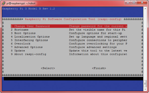
FIGURE 6-14 The Raspberry Pi software configuration tool
Now use the arrow keys to scroll down and select Advanced Options and then press ENTER. This will open up a new menu; scroll down to Audio, select it, and press ENTER again.
Once here, you will be provided with the three options. Select the Force 3.5mm jack option, as shown in Figure 6-15.
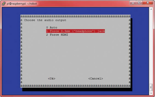
FIGURE 6-15 Choosing the audio output using raspi-config
Next, you’ll be returned to the original menu shown in Figure 6-14. From there exit the configuration tool by pressing the right arrow key twice (to highlight Finish) and then pressing ENTER.
Playing Sounds from the Terminal
To play sounds from the terminal, you first need some sounds to play! The audio files for this project and the next one can be found online at https://nostarch.com/raspirobots/. If you have downloaded all of the software in bulk, then you’ll already have the files. Alternatively, you can grab the two audio files off the internet with a few easy commands. Either way, first create a new directory called sounds inside the folder where you’re storing all of your robot programs. For me, this command looks like:
pi@raspberrypi:~/robot $ mkdir sounds
If you downloaded the files in bulk, transfer the files beep.wav and horn.wav into this new folder. If you want to download the files directly, then change into that directory as follows:
pi@raspberrypi:~/robot $ cd sounds
Finally, to download each of the audio files, use this command:
pi@raspberrypi:~/robot/sounds $ wget https://raw.githubusercontent
.com/the-raspberry-pi-guy/raspirobots/master/sounds/beep.wav
Followed by this one:
pi@raspberrypi:~/robot/sounds $ wget https://raw.githubusercontent
.com/the-raspberry-pi-guy/raspirobots/master/sounds/horn.wav
Now if you enter ls in the terminal, you’ll find two new audio files—horn.wav and beep.wav:
pi@raspberrypi:~/robot/sounds $ ls
horn.wav beep.wav
The former is the file we’ll use in this project. Before you test horn.wav, increase the software volume level of your speaker to its maximum with this command:
pi@raspberrypi:~/robot/sounds $ amixer set PCM 100%
Also ensure that any physical volume control on your 3.5 mm speaker is at its maximum. Then, to play horn.wav through your 3.5 mm speaker, you’ll use aplay, a terminal-based sound player, like so:
pi@raspberrypi:~/robot/sounds $ aplay horn.wav
Playing WAVE 'horn.wav' : Signed 24 bit Little Endian in 3bytes,
Rate 44100 Hz, Stereo
You should hear your robot emit a single car horn noise!
Playing Sound Using the Wiimote Program
Now that you understand how to play sound files through the terminal, you can add this functionality to the Wiimote program from earlier in the chapter. This means that your robot will be able not only to trigger a light show, but also to sound a car horn whenever you wish!
To accomplish this, we’ll call the aplay command from inside Python. Navigate back into the robots directory and then reopen the NeoPixel/Wiimote code with this command:
pi@raspberrypi:~/robot $ nano neo_remote_control.py
Then, enter the additions in Listing 6-4 into your own code. As before, all of the unchanged code has been omitted. Alternatively, you can grab the modified file from the book’s website.
import gpiozero
import cwiid
import time
from rpi_ws281x import *
➊ import os
robot = gpiozero.Robot(left=(17,18), right=(27,22))
--snip--
while True:
buttons = wii.state["buttons"]
if (buttons & cwiid.BTN_PLUS):
colorWipe(strip, Color(255, 0, 0)) # Red wipe
--snip--
if (buttons & cwiid.BTN_B):
colorWipe(strip, Color(0, 0, 0)) # Blank
➋ if (buttons & cwiid.BTN_A):
os.system("aplay sounds/horn.wav")
x = (wii.state["acc"][cwiid.X] - 95) - 25
--snip--
if (turn_value < 0.3) and (turn_value > -0.3):
robot.value = (forward_value, forward_value)
else:
robot.value = (-turn_value, turn_value)
LISTING 6-4 The modified NeoPixel/Wiimote code with car horn sound effect
The additions required are simple and span only three lines. The first thing to note is at ➊, where the os library is imported. The os library enables us to use the functionality of the Pi’s operating system inside of a Python program.
This comes in handy at ➋. Here, the program detects whether the user has pressed the A button on the Wiimote. If so, the same aplay terminal command you used earlier is called using os.system. Notice that there is also a short filepath to the horn.wav sound, as this file is stored in a different directory than the program.
Running Your Program: NeoPixels, Sound Effects, and the Wiimote Control
Save your work and run it with the same command as the previous project:
pi@raspberrypi:~/robot $ python3 neo_remote_control.py
Your robot will now respond exactly as before, with accelerometer control. You’ll also be able to trigger the same lights as before. Now try pressing the A button: you should hear your robot honk its horn!
ADDING BEEPING TO THE OBSTACLE AVOIDANCE PROGRAM
In this project, we’ll revisit the obstacle avoidance program you already coded in Chapter 5, and add a beeping sound to alert you when your robot has detected an obstacle within a 15 cm range.
Integrating the Beep Sound into the Obstacle Avoidance Program
You’ve already set up your speaker and configured the necessary software, so we can jump straight into integrating the beep sound into the obstacle avoidance program.
We’ll do this as we did with the horn: by calling aplay inside of the Python program. I recommend using cp to create a new copy of the obstacle avoidance program. I’ve called mine beep_obstacle_avoider.py. Enter the modifications I made as shown in Listing 6-5.
import gpiozero
import time
➊ import os
TRIG = 23
ECHO = 24
trigger = gpiozero.OutputDevice(TRIG)
--snip--
while True:
dist = get_distance(trigger,echo)
if dist <= 15:
➋ os.system("aplay sounds/beep.wav")
robot.right(0.3)
time.sleep(0.25)
else:
robot.forward(0.3)
time.sleep(0.1)
LISTING 6-5 The beep_obstacle_avoider.py program
Just as before, we import the os module ➊. Then, if the sensor detects an object less than or equal to 15 cm away, the program plays the beep sound ➋ and the robot changes course.
Running Your Program: Beeping Obstacle Avoidance
Save your work and run it with the following command:
pi@raspberrypi:~/robot $ python3 beep_obstacle_avoider.py
Your robot will now avoid obstacles and beep when it does so!
Challenge Yourself: Add Sound Effects to Your Other Projects
Now that you know the relatively simple process of adding audio effects to a program, why not revisit the other programs you have written over the course of this book and add sound to them? You could use your phone to record your own noises, or you can use online sound libraries that provide free audio files. For example, take a look at Freesound: https://freesound.org/.
SUMMARY
In this chapter you have decked out your robot with some super-bright NeoPixels and given it the gift of sound, too! Over the course of three different projects, we’ve covered everything from the theory of RGB LEDs to how to play audio in the terminal.
In the next chapter, we’ll make your robot a little bit more intelligent! I’ll guide you through the process of giving your two-wheeler the ability to autonomously follow lines.