Table of Contents for
Learn Robotics with Raspberry Pi
 Learn Robotics with Raspberry Pi
Published by
No Starch Press, 2018
Learn Robotics with Raspberry Pi
Published by
No Starch Press, 2018
- Cover Page
- Title Page
- Copyright Page
- Dedication
- CONTENTS
- CONTENTS IN DETAIL
- ACKNOWLEDGMENTS
- FOREWORD
- INTRODUCTION
- CHAPTER 1: GETTING UP AND RUNNING
- CHAPTER 2: ELECTRONICS BASICS
- CHAPTER 3: BUILDING YOUR ROBOT
- CHAPTER 4: MAKING YOUR ROBOT MOVE
- CHAPTER 5: AVOIDING OBSTACLES
- CHAPTER 6: CUSTOMIZING WITH LIGHTS AND SOUND
- CHAPTER 7: LINE FOLLOWING
- CHAPTER 8: COMPUTER VISION: FOLLOW A COLORED BALL
- NEXT STEPS
- RASPBERRY PI GPIO DIAGRAM
- RESISTOR GUIDE
- HOW TO SOLDER
- RUN PROGRAM ON STARTUP
- Learn Robotics with Raspberry Pi®: Build and Code Your Own Moving, Sensing, Thinking Robots
- Learn Robotics with Raspberry Pi®: Build and Code Your Own Moving, Sensing, Thinking Robots
3
BUILDING YOUR ROBOT
ROBOTS COME IN EVERY SHAPE, SIZE, AND DESIGN YOU COULD POSSIBLY IMAGINE——FROM THE ROBOTIC ARM ON THE INTERNATIONAL SPACE STATION TO TOYS BUILT FOR ENTERTAINMENT.
Robots can be customized for specific tasks, but in order to do this, you’ll first need to understand and build a robot’s basic components. In this chapter, I’ll show you how to make the base robot that you’ll modify and improve for the rest of the book. Once we’ve programmed it, this robot will be able to move around according to your instructions. In later chapters, we’ll add sensors, lights, and a camera to make your robot flashier and smarter!
YOUR FIRST ROBOT
Robots that move around can be split into two distinct groups: ones with wheels and ones without. Those without wheels are often humanoid, meaning they have two legs and resemble a human being, or might be based on animals, like dogs (see some examples in Figure 3-1). These robots are usually very difficult both to create and to program because the builders have to take into account balance, movement, and a huge range of other factors.

FIGURE 3-1 Robots from Boston Dynamics
In contrast, robots that use wheels (or tracks) make up the vast chunk of real-world robots and don’t have complicated balancing issues, which makes them perfect for hobbyists and makers like us. One famous wheeled robot is NASA’s Curiosity rover, which has six wheels and has been moving around Mars since 2012, discovering and doing amazing science in the process!
For your first robot, you’ll create a two-wheeled robot like the one shown in Figure 3-2. Two-wheeled robots are a great starting point in the world of robotics. Your robot will be able to go forward and backward, and turn left and right using one motor for each wheel.
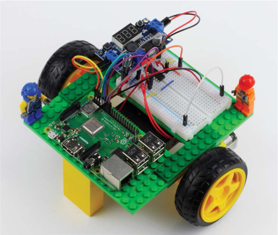
FIGURE 3-2 My complete Raspberry Pi robot. By the end of the chapter, you’ll have one too!
The two-wheeled robot you’ll make in this chapter has just the right mix of features—it’s affordable, accessible, and maneuverable!
WHAT YOU’LL NEED
In addition to your Raspberry Pi, you’ll need some other basic elements to assemble your robot. As with all things in the maker-world, you have a huge number of choices for the materials and components you can use based on what you have available.
If this is your first time working with the Raspberry Pi and electronics, I’d suggest getting the same parts I have, as listed here, so you can follow the instructions word for word. If you have some experience and your own ideas, then feel free to explore; you don’t have to stick to what I recommend.
Breadboard I recommend a 400-point breadboard with power rails like the one used in Chapter 2.
Jumper wires I recommend a variety pack of breadboard wires with different colors and lengths.
Chassis This is the robot’s body, and should be at least 6 inches by 5.5 inches. I’m using LEGO (see the next section for options).
Two brushed DC motors Use 5 V to 9 V, 100 mA to 500 mA motors with tires and an integrated gearbox.
Battery holder Find one that fits six AA batteries.
Six AA batteries Either disposable or rechargeable is fine; I recommend Panasonic’s Eneloop rechargeable batteries.
LM2596 buck converter This is a step-down voltage buck converter.
L293D motor driver This is a motor controller integrated chip.
You will also need a variety of screwdrivers, a hot glue gun, a multimeter, and a soldering iron.
The next few sections provide more details on each component and what it does. If you want to skip straight to building your robot, go to “Assembling Your Robot” on page 60.
Chassis
The chassis is the base frame of the robot; you can think of it as the robot’s body. The chassis forms the platform on which you’ll mount your Raspberry Pi and other parts.
You can create your chassis with a number of different materials, but any design you make will need to satisfy the following three criteria. The chassis needs to be:
A strong, stable platform All of your robot’s electronics will be mounted to the chassis, so you need to make sure it isn’t fragile.
At least 6 inches by 5.5 inches As you progress through this book, you’re going to add more and more components to your build, so you’ll need space for growth. Don’t worry about making your robot chassis massive, but make sure it isn’t tiny, either!
Easy to modify Having a chassis that is easy to modify, expand, and change means that you can customize your robot even more in the future!
LEGO is my preferred material for first-time robot building. Everybody’s favorite toy bricks can make the perfect robot chassis. With an immense and accessible array of bricks and pieces, you can easily make chassis designs of all shapes and sizes with LEGO parts. In this chapter I’ll show you how I have constructed my chassis using the parts in Figure 3-3.
Cardboard is another good option because you can get it anywhere and it’s easy to work with. Some simple cutting, folding, and gluing can shape your cardboard into all sorts of chassis shapes. The thicker the card, the better! You can make a solid card-based chassis from any recycled cardboard box—a shoebox, Amazon packaging, a cereal box, you name it!

FIGURE 3-3 The LEGO pieces I used to make the chassis of my robot from Figure 3-2
If you have access to some simple wood-crafting tools, like a wood saw, then making a robot chassis out of wood may be a good idea. Inexpensive wood and wood composites, like like pine and medium-density fiberboard (MDF), make a strong, stable chassis at a low price.
A custom plastic chassis can form the basis of a sweet-looking robot. You can purchase acrylic (Plexiglas, Lucite, Perspex) sheets relatively inexpensively and cut them with a handsaw or, better yet, a bandsaw. Better still, if you have access to one, a laser cutter allows you to create perfect robots to exact, computer-given dimensions and designs, as you can see in Figure 3-4. Check your local area to see if there is a makerspace/hackerspace that has a communal laser cutter you could use.
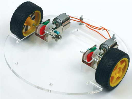
FIGURE 3-4 The base of a custom laser-cut robot chassis that I designed and made in a makerspace in Cambridge, UK
You could also work with plastic using a 3D printer. 3D printers work by heating up and extruding layers of plastic to build an object layer by layer. You can design your chassis in computer-assisted design (CAD) software on a computer, or you can even download and print other people’s designs from the internet. 3D printers are becoming much more commonplace, so you may be able to find one at a local library, makerspace, or hackerspace, or you may even know someone who owns one.
If you don’t want to make your own chassis, you can buy a variety of basic kits online. Most of these are either one or two layers of acrylic that can be fastened together with screws and pillars (see the example in Figure 3-5). You can find a premade chassis by searching “robot chassis” on the internet. eBay usually has some of the best deals.

FIGURE 3-5 A premade chassis with motors
Motors
Without motors, your robot can’t move. And a robot that can’t move isn’t much of a robot! Let’s look at a few motor basics so you know what kind of motors to use when.
What Is a Motor?
An electric motor converts electrical energy into mechanical energy. Motors come in many different sizes and designs, and a wide range of prices. For this book, you’ll want to get two (one for each wheel) of the cheapest type: DC motors. These are the most common kind of motor and can be found in everything from trains to desktop fans.
DC stands for direct current, which means the electric current must flow through the motor in one direction for it to work. Alternatives to DC motors—such as AC (alternating current) motors and stepper motors—tend to be more expensive, harder to use, and more complicated electronics-wise, so we’ll stick with DC for now.
The super-simple motors we’ll use have two terminals. A terminal is just a point where electricity can enter and leave a component. When you apply a voltage over these terminals, the motor shaft will spin. If you change the direction of the voltage (sometimes referred to as reversing the voltage), the motor will spin the other way.
You can spend ever-increasing amounts of money to get ever better motors. It’s a good idea to start off really cheap to get the basics right before investing in more expensive equipment.
Motor Options
For your first robot build, get a pair of geared brushed (not brushless) DC motors. In both brushed and brushless motors, electricity creates electromagnetic forces that are responsible for spinning the motor shaft; however, brushless motors are more complicated and require additional expensive circuitry to function. Brushless motors are usually used for more serious tasks, like remote-controlled model airplanes and drones.
You can pick up a pair of brushed DC motors from any of the usual online retailers for less than $10 (see “Where Should You Buy Parts?” on page xix for a list of retailers). Before buying, ensure you take a look at the motor’s specification. You’ll need to consider a few of the following factors.
I advise getting motors rated between 5 V and 9 V. If your motors’ voltage requirement is too high, you’ll struggle to power them and will likely need more batteries. If the voltage of your motors is too low, the voltage provided by your power source (see the next section) may cause overheating and damage!
The amount of current a motor draws is also very important. The more current needed, the quicker your batteries will deplete and the harder the motor will be to control. On the other hand, less current equates to less powerful motors that may struggle to haul your robot around. Try to ensure that your motors are rated at no more than 500 mA each. Too much current may also overload the motor controller we’ll be using later.
A cheap motor will usually have a high number of revolutions per minute (RPM), spinning around 1,000 to 3,000 times in a single minute, which is far too fast for a small robot. At these RPMs, each motor will create very little torque. Torque is the driving force, and the smaller it is, the more your robot will struggle to move along a surface. To fix this, your motors need a gearbox to bring the RPM down and increase the torque. The ratio of the original RPM to the new geared, lower RPM is called its reduction rate, and 48:1 is a decent reduction rate for this project. When searching for your supplies, make sure you’re looking for motors that have a small gearbox preinstalled by using search terms like “geared hobby motors.”
Motors are not very useful without wheels. Most motors will have a shaft you can fit a tire onto that will revolve when the motor runs and consequently turn the tires. If you buy motors without tires, you’ll have to source ones that will fit the shafts of the motor you have purchased, which can be hard. I recommend buying motors that come with tires. Grippy rubber wheels will provide you with good control. Alternatively, you could always try making your own wheels, especially if you have access to precision equipment like a 3D printer.
The motors that I use, shown in Figure 3-6, fit all of these criteria. These are common hobby motors that have a gearbox and come with their own set of tires. They can also run off voltages anywhere between 3 V and 9 V and draw around 100 mA of current each. You can pick up a pair of these for as little as $5. I sourced mine from eBay by searching for “robot motor with tire,” though they’re widely available from many other places.

FIGURE 3-6 My robot’s motors and tires
Most DC motors will come without wires attached to the two terminals. If this is the case with your motors, you’ll have to solder wires onto them. Soldering is the process of electrically joining two components by melting a filler metal called solder between them. This can seem very daunting, but don’t worry—it’s really easy and a super important skill! Take a look at “How to Solder” on page 204 for more information.
If you really want to avoid soldering, you may be able to find motors online that come with wires already soldered and attached to the terminals. Just keep in mind that these may be hard to source and will probably command a higher price!
Batteries
To make sure our robots can move around by themselves, we’ll power them with batteries so we don’t have trailing power cables. A battery is an electrochemical device that stores energy.
For this book, you’ll power your robots with AA batteries. Not only are these common and cheap, they are also safe and easy to use. A single AA battery will usually provide between 1.2 V and 1.5 V of power, and they can be chained together to provide larger voltages. The number of AA batteries you need depends on the voltage of your motors. Six AA batteries chained together in a battery holder will provide an output voltage between 7 V and 9 V, which should be the right amount for your robot.
AA batteries come in two variations: primary (nonrechargeable) and rechargeable. Primary batteries are cheaper but can be used only once and then need to be responsibly thrown away. This means that, over time, the cost of using primary batteries will creep up. I recommend investing in some high-quality rechargeable batteries and a decent charger. The initial expense can be higher ($20–$30), but you’ll save money in the long run and be more environmentally friendly in the process! I use Panasonic’s Eneloop rechargeable AA batteries, shown in Figure 3-7. Bear in mind that rechargeable batteries often have a slightly lower voltage than primary batteries (for AA, usually 1.2 V rather than 1.5 V).
To store and connect these batteries, you’ll need a battery holder. This will both hold your batteries in place and connect the terminals of your batteries together so that you have just one positive and one negative wire to connect to get power out of all of them. These are widely available online. I picked up the six AA battery holder with an on-off switch shown in Figure 3-7 from eBay for $1.
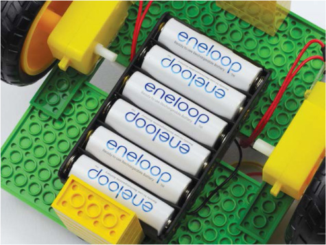
FIGURE 3-7 My battery holder with six AA Eneloop rechargeable batteries
Voltage Regulator
WARNING
Some buck converters require voltage “headroom” to function correctly. For example, the LM2596 module that I’m using requires the input voltage to be at least 2 V higher than the output voltage. This means that, in the worst-case scenario, the maximum regulated voltage out of my LM2596 module is 7.2 V – 2 V = 5.2 V. This is not a problem when I’m using six AA batteries (which provide that 7 V to 9 V), but if I used four AA batteries (providing only 6 V), then I might not be able to get a 5 V output and would have insufficient power for a Raspberry Pi. If you’re using a different buck converter, make sure to check its internet listing or datasheet for details.
While your motors will happily run off the 7 V to 9 V your batteries provide, your Raspberry Pi will certainly not. Your Raspberry Pi operates on strictly 5 V (with a tolerance of 0.1 volts on either side). If you provide less voltage, your Pi won’t boot. If you provide any more, you’ll break your Pi! Providing too much voltage will allow too large of a current to flow through your Pi’s internal components and the Pi will blow up (which, in reality, means a small plume of blue smoke will come from the processor, which will be irreversibly damaged).
To avoid blowing your Pi up, you can use a simple voltage-regulating component called a step-down buck converter to turn the 7 V to 9 V into the 5 V your Pi needs. A step-down buck converter reduces an input voltage to a desired output voltage. We’ll use a converter based around the LM2596 chip, which has been neatly arranged into an easy-to-use module board, as shown in Figure 3-8. This module can take a voltage input between 4 V and 40 V and reduce it to anything between 1 V and 35 V. I’ll show you how to set yours to 5 V for your Raspberry Pi later in the chapter.
You can pick up an LM2596 module, or another similar buck converter, online for a few dollars. If you decide to go for a different model, ensure that it is able to output at least 2 A of current continuously. This information should be available in the listing of the product or in its datasheet, a reference that details the technical characteristics of a component. Also note that you should purchase a buck converter that uses screw terminals for the inputs and outputs—this makes things easier and saves you from more potential soldering.
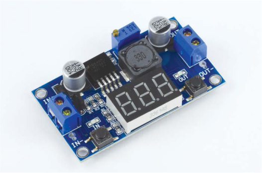
FIGURE 3-8 An LM2596 buck converter module
Motor Controller
Your DC motors will draw up to 500 mA each. For comparison, the Pi’s GPIO pins can provide only 20 to 50 mA in total. This means that your motors will need to be powered directly from your separate battery pack. This isn’t a problem, but it does mean the Raspberry Pi isn’t directly connected to the motors, so you’ll need a motor controller to interface between the motor, its power source, and your Raspberry Pi. A motor controller will allow you to use your Pi to turn your motors on or off, and to control their speed.
There are many different motor controllers available, in a wide variety of packages. You can get driver chips, module boards, or even HATs (official Raspberry Pi Hardware-Attached-on-Top). Each option has advantages and disadvantages.
In this book, I’ll use an integrated chip (IC) called the L293D. A breadboard-friendly IC, like my L293D in Figure 3-9, is a small black box that contains a collection of miniaturized electronic components, like resistors, transistors, and capacitors. You can insert the legs of the IC into the breadboard and wire them up to provide extra circuit functionality. The L293D gives you complete control over up to two independent motors—perfect for your first robot!
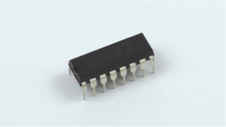
FIGURE 3-9 An L293D motor controller chip
For more specific details on the vast capabilities of the L293D motor driving chip, just search online for its datasheet. You can pick up an L293D for less than $4 online.
Recommended Tools
Over the course of the robot-building process and the rest of the book, you’ll need some basic tools. This is a list of all the tools you’ll need, as well as a few optional tools that aren’t strictly necessary but might help you:
- Variety of screwdrivers
- Hot glue gun
- Multimeter
- Soldering iron
ASSEMBLING YOUR ROBOT
Once you have the components for your robot, you can start assembling and wiring it up! If you bought the same components as the ones I listed earlier, you can follow my instructions exactly. If you bought or made slightly different components, you may have to get a bit creative, but the following instructions should be an excellent guide no matter what parts you have.
Making the Chassis
As mentioned, I’m making my robot chassis out of LEGO pieces, so that’s what these instructions will use.
You can make a chassis out of LEGO pieces in an infinite number of ways with an infinite number of brick combinations. My very simple chassis uses the following parts, shown in Figure 3-10:
- Two 8×16 plates
- Four 2×8 plates
If you want to purchase these exact LEGO pieces and follow this process precisely, you can use the “Pick A Brick” service at https://shop.lego.com/en-US/Pick-a-Brick/. Here you can order individual pieces for your own custom creations by searching for the pieces using their element IDs. You’ll need:
- Two 8×16 plates with ID 4610353
- Four 2×8 plates with ID 303428

FIGURE 3-10 The LEGO pieces I’m using to build my chassis
Plug these ID numbers into the Element ID search box and you should find them.
It is worth noting that, according to the LEGO website, you may have to wait up to 10 business days for your parts to arrive! If you choose to make your chassis from LEGO pieces, you’ll need some other bricks later on in the building process, so I suggest ordering all the bricks you need at once.
The 8×16 plates are perfectly sized to mount a Raspberry Pi and a breadboard each. I’ve made mine with a gap between the two LEGO plates that makes it easy to feed the wires through neatly.
To follow my design, place your 8×16 plates two LEGO studs apart, and attach two 2×8 plates on the top to fasten the larger plates together. Fasten the other two 2×8 pieces on the underside to make it extra sturdy, as shown in Figure 3-11.

FIGURE 3-11 The completed LEGO chassis: on the right is a close-up of the joints made with the 2×8 plates
This sandwiches the plates together to create a sturdy and stable platform.
Attaching the Motors
With your chassis constructed, you can attach and wire up the various components, starting with the motors. Before you attach the motors to the body of your robot, ensure that they have wires soldered to their terminals! Again, see “How to Solder” on page 204 to learn how to do this.
You’ll mount your motors to the bottom of your chassis, with the wheels as central to the body as possible to give your robot a small turning circle—meaning it can make tighter turns. I’ll give you a few options for securing the motors. Whichever option you choose, make sure that your motors are aligned and as parallel as possible. Nonparallel motors will cause conflict in the direction your robot travels and may prevent your robot from moving in a straight line.
Permanent Option: Glue
Gluing with either a hot-glue gun or superglue will securely and permanently bond your motors to your chassis. This is my preferred way of attaching the motors to the chassis, but think twice before you glue, since it’s permanent! Make sure you’re completely satisfied with the motor positions before you commit.
A neat layer of glue as shown in Figure 3-12 ensures that your motor joints are secure and do not wiggle.
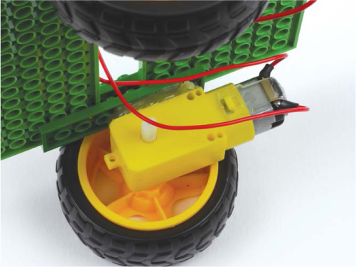
FIGURE 3-12 Hot glue used to attach the motors
Less Permanent Option: Velcro or Screws
Traditional hook-and-loop fastener material (more commonly known as Velcro) is a great way of fixing things together in a nonpermanent way, with no mess and no tools required. My favorite brand is 3M Dual Lock, which is an incredibly strong hook-and-loop pad, though slightly more expensive than other solutions at around $15 per meter. Hook-and-loop fasteners usually have an adhesive back so you can just cut off as much as you need, peel the covering away, and stick it onto your chassis. If you find this isn’t quite strong enough, or has too much flex for mounting your motors, I recommend adding a little bit of glue around the edges of the Velcro/Dual Lock.
Alternatively, another less permanent option is using screws. If you’ve made a wood, laser-cut plastic, or 3D-printed base, you could screw your motors to the chassis. Some motors even come with brackets and screws for this exact purpose. This is a secure way of doing things, and you can always unscrew your motors to use in a different project further down the line.
Even Less Permanent Option: Sticky Tape
Double-sided sticky tape is useful for securing parts together easily and without fuss, similar to Velcro, although this is the weakest option.
Stabilizing the Robot
After you’ve attached the motors to the bottom of your chassis, feed the two wires of each motor through the gap up onto the top of your platform, as shown in Figure 3-13.

FIGURE 3-13 The chassis with motors connected, and wires threaded through the gap
With your two motors attached in the center of the chassis of your robot, you may notice that the platform is unstable and resting on its heaviest side. Don’t worry: you can easily fix this!
Stabilizers will prevent your robot from rocking and allow for smooth movement. You need only one stabilizer on either side, and this can be made out of anything. Because I’m using a LEGO chassis, I’ve constructed mine out of LEGO bricks! I put two five-deep 2×4 brick posts on the front and the back underside of my robot; these will stabilize the weight but won’t touch the ground, so they shouldn’t obstruct movement when running on a smooth surface. These guides have eliminated the rocking entirely; see Figure 3-14.

FIGURE 3-14 The chassis with LEGO stabilizers on the front and back underside
If you’re also using LEGO parts, you may need more or fewer bricks—just make sure your stabilizers span from the bottom of the chassis to just above the floor. Be careful not to make the stabilizers too long, as they may hinder your robot’s movement or suspend its motors above the ground completely!
If you don’t want to make your stabilizers out of LEGO bricks, you can use any other material (pieces of plastic, wood, etc.) that fits between the chassis and the floor, and that you can firmly attach to your chassis.
A common option is to use one or two caster wheels or balls; these are nonmotorized wheels or balls used solely to balance the robot. You should be able to find these online in the dimensions you need—just measure from the chassis to the floor when the chassis base is level—and you’ll often find they have screw mounts, which makes them a particularly good option if your chassis is made out of wood or plastic.
Many of the robot platforms you can buy online come as complete kits with the motors, wheels, and caster wheel. This can be a great way to save time, especially as all the holes have been drilled for you.
Attaching the Batteries
Now that you have your motors attached to your robot, you can fix your battery holder and batteries in place. Figuring out where to mount the batteries involves two vital considerations:
Space Where is there enough space for your battery holder? Will the wires from the battery holder reach the top of your chassis? Will your battery holder obstruct the movement of the robot in any way?
Access At some point you’ll need to remove the batteries and either replace or recharge them, so you need to make sure you have easy access to your holder. Don’t make the mistake of permanently sticking your battery holder on, only to not be able to get at the batteries inside!
WARNING
Ensure that the positive and negative wires of your battery holder don’t accidentally touch while the batteries are in place. If they do, they’ll create a short circuit, which will cause rapid heating and potentially even damage your batteries.
I have mounted my battery pack on the underside of my LEGO chassis and between the motors, as shown in Figure 3-15. This is a good option because it leaves the top free to mount the components you need to access more regularly, like your Pi, while still giving you easy access to the batteries to replace them. I’ve mounted the holder using some trusty 3M Dual Lock. Try to center the battery holder to keep the weight balanced.
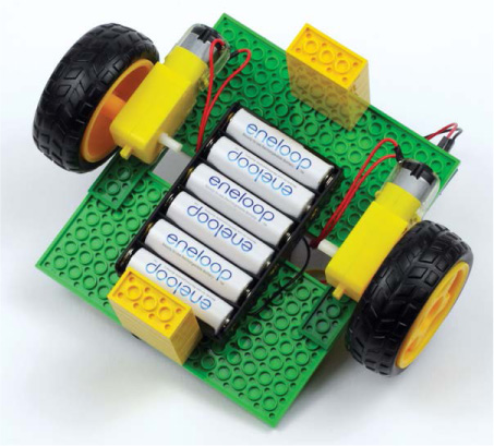
FIGURE 3-15 The underside of the robot with a battery holder attached
Once you’ve fixed your battery holder into place, insert some new or fully charged batteries into it and thread the wires from the holder up to the top of the chassis.
Mounting the Raspberry Pi, Breadboard, and Buck Converter
After you’ve set up your motors and batteries, flip your robot the right way up to mount the key electronics: your Raspberry Pi, breadboard, and buck converter.
The 8×16 LEGO plates are perfectly sized to fit a Pi and a breadboard each. As you can see in Figure 3-16, I have mounted my Raspberry Pi on one plate and the breadboard on the other. In the bottom-right corner, you can also see the LM2596 buck converter. This is my recommendation for positioning your parts.
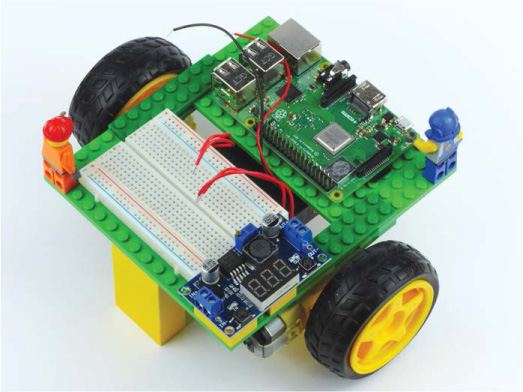
FIGURE 3-16 The chassis with the Raspberry Pi, LM2596, and breadboard mounted
Since you’ll likely want to use your Pi again, I’d recommend a nonpermanent adhesive option. I used sticky tack to delicately and nonpermanently attach my Pi. Most breadboards come equipped with an adhesive back, so I simply peeled off the cover and used the adhesive to securely fasten my breadboard to the LEGO plate. If your breadboard has no adhesive underside, then I recommend using sticky tack for that, too.
Depending on what your chassis is made out of, you may choose a different way of fastening your electronics. The latest Raspberry Pi and its previous models come with screw holes, so you could use a set of small screws to fasten your Pi to a wood or plastic chassis.
I attached the LM2596 buck converter module next to my breadboard using more sticky tack, suspended on two 2×2 LEGO bricks. When you do this, ensure that the screw terminals of your voltage regulator are easily accessible and not blocked by your breadboard or anything else, because you’ll need to connect wires to these later.
Wiring Up Power to the Raspberry Pi
Before you can wire up your motors, you need to set up the power going to the brain of your robot: the Raspberry Pi.
As mentioned, it’s crucial that your Pi gets 5 V (±0.1 V), and not the 7 V or 9 V (or other voltage) that your batteries provide. This means you’ll need to adjust your buck converter to output precisely 5 V.
The best way to do this is with the help of a tool called a multimeter, shown in Figure 3-17. You should be able to pick up a multimeter for as little as $10 online.
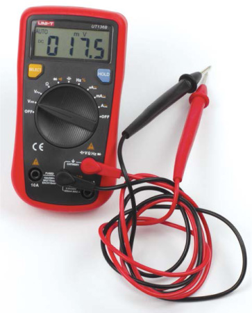
FIGURE 3-17 A multimeter, set to read voltage
A multimeter is an electronics measuring instrument. A normal multimeter can measure voltage, current, and resistance. We’re interested in measuring the voltage.
Some voltage converters, like the LM2596 module I am using, do have a small LED screen that displays a voltage readout. While in theory this eliminates the need for a multimeter in this case, it is still good practice to use a multimeter to double-check the output voltage. A multimeter will come in handy in the future too, so it’s a wise investment.
We’re going to connect the power through the GPIO pins on your Pi. Follow these instructions carefully, taking your time, and your Pi will have power without blowing up! But don’t worry too much: this way of powering a Pi has been tried and tested many times and is totally safe when done right!
Setting Up the Converter
Start by setting up your buck converter using the following instructions—you won’t connect it to the Raspberry Pi just yet. Flip to the circuit diagram in Figure 3-21 to see a final diagram of the buck converter setup. Check out Figure 3-19 for a close-up image of the buck converter too.
- Connect both wires from your battery pack into separate columns and rows of your breadboard. Most breadboards will have two rows running along each edge that are lined with red and blue or have a + or – sign at the end; these rows are known as power rails. To help keep track of where your negative and positive power lines are connected, connect the black (negative) wire from your battery pack into one side of your breadboard’s blue – power rail, and the red (positive) wire to that side’s red + power rail. Check out Figure 2-4 on page 34 for a diagram of these power rails.
BATTERY PACK
BREADBOARD
Red, positive wire
+ power rail
Black, negative wire
− power rail
Now we’ll connect the LM2596 module. Most LM2596 buck converter modules come equipped with Philips-head screw terminals. To connect a wire to these terminals, simply unscrew the terminal you want, place a wire in the hole at the front, and then tighten the screw to make a firm connection.
- Take one red and one black M-M jumper wire and insert them into the positive and negative ground rails, respectively. Ensure that the ends of the wires do not touch during this. Now unscrew the screw in the terminal labeled VIN (for voltage in) of your LM2596 module, insert the red positive wire, and then tighten the screw terminal. Then insert the black negative wire into the ground terminal labeled GND (for Ground) on the same side of your LM2596 module, as shown in Figure 3-18. Make sure that you get the positive and ground wires the right way around!
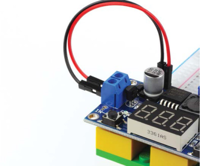
FIGURE 3-18 The 7 V–9 V and ground lines running into the LM2596 buck converter
LM2596
CONNECTION
VIN
Red wire, + power rail
GND
Black wire, − power rail
- Next, turn on your multimeter and set it to read voltage—on most multimeters you do this by turning the dial in the middle to V. Then insert the multimeter’s red positive lead into the VOUT (voltage out) terminal of your buck converter, and insert the multimeter’s black negative lead into the GND terminal on the same side (see Figure 3-19). You should see a reading of the output voltage of your buck converter appear on the multimeter. Don’t worry about the value of the reading just yet!
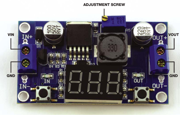
FIGURE 3-19 A close-up of the buck converter
- With the multimeter connected so you can see how the voltage changes, use a screwdriver to twist the adjustment screw on the top of your buck converter (check back to Figure 3-19). Insert your screwdriver, and as you twist either left or right your voltage reading should change. Work out the correct direction you need to twist the adjustment screw, and then keep twisting the screw until your multimeter reads 5 V (±0.1 V), as shown in Figure 3-20. This requires a little trial and error!
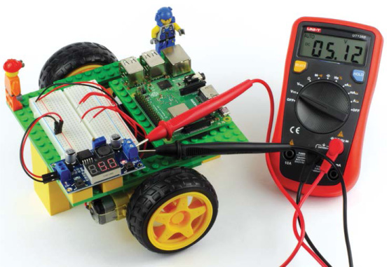
FIGURE 3-20 The multimeter reading 5 V from the output of the buck converter
NOTE
Slightly overpowering your Raspberry Pi with a voltage of no more than 5.1 V can be beneficial. It can prevent your Pi from cutting out due to the small voltage drop from the batteries that can occur when the motors are running, for example.
- Once you are satisfied that your multimeter is reading 5 V (±0.1 V), unplug it from the output of your buck converter and turn it off.
Wiring Up the Converter
Now that you have adjusted the output voltage of your buck converter, you can wire it up to your Raspberry Pi. Make sure your batteries are off, or even take the batteries out of your battery holder, before wiring up the converter.
- Grab two M-F jumper wires—the convention is to use one red for positive and one black for negative (Ground). You’ll connect the male ends of the jumper wires to each terminal of your converter’s output. As usual, connect red to the positive output (VOUT) and black to the negative output (GND) of your LM2596 module. Then, connect the red wire to physical pin 2 on your Raspberry Pi (+5 V). Finally, connect the ground wire to physical pin 6 of your Pi (Ground). See Figure 3-21 for a breadboard diagram and image showing how your Pi should look. Also refer to “Raspberry Pi GPIO Diagram” on page 200.
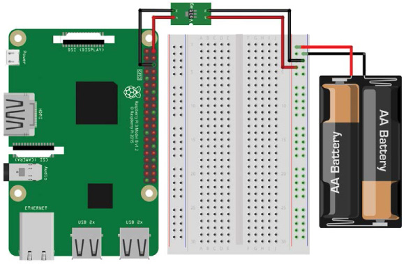
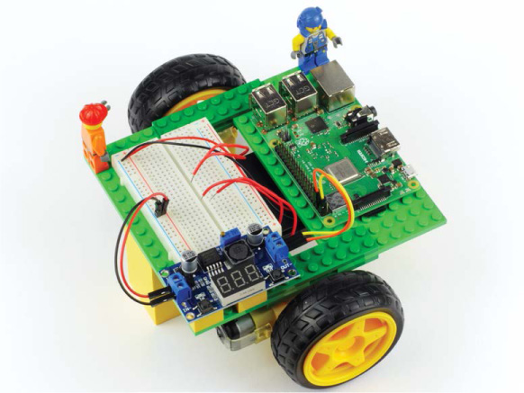
FIGURE 3-21 A breadboard diagram of the buck converter circuit (top); the wired-up LM2596 converter (bottom)
WARNING
Before you proceed, double-check that you are happy with your wiring and the voltage your buck converter is providing. If you are ever in doubt, unplug your Pi and check the voltage again using your multimeter before you turn the power on. It never hurts to check multiple times!
Good work—you’ve finished wiring your buck converter up to the Pi’s GPIO pins! Now flick the power switch of your battery holder on (or reinsert the batteries), and you should see your Raspberry Pi spring to life just as if you had connected power to the micro USB port.
Wiring Up the Motors
The final stage of your base robot build is to wire up your motors to your motor controller, and then wire your motor controller to your Pi. Bear in mind that this process may be different if you are using a different motor controller than I am.
WARNING
Before you begin, ensure that your Raspberry Pi is receiving no power and that your battery holder has the batteries removed or is turned off. Making sure your Pi is off when you’re wiring up circuits is very important to prevent an accidental short that could damage your components or your Pi.
Connecting the L293D Motor Controller
The following instructions are for the L293D motor controller chip that I’m using:
- Insert your L293D firmly into your breadboard, ensuring that all of the legs are in separate rows and are not connected to other components. To do this, position the chip so it straddles the gap running down the middle of your breadboard, as shown in Figure 3-22. The legs of ICs like the L293D often are not quite straight, so you may struggle to fit it into your board. If this is the case, take your L293D and press each side lightly against a flat surface to bend the legs into right angles.
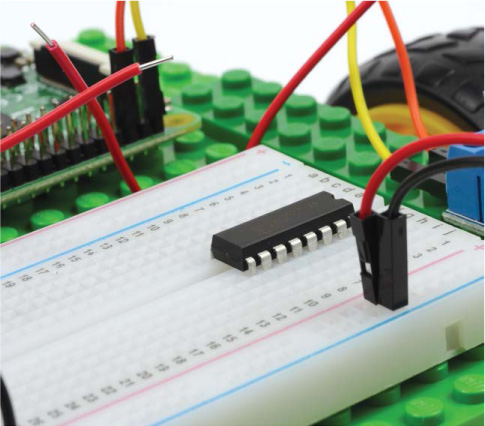
FIGURE 3-22 The L293D inserted into my breadboard
NOTE
You may have noticed that you are using both sets of power rails on your breadboard. One power rail has the +7 V to 9 V from your batteries, whereas the other one has the +5 V from your Raspberry Pi. Due to this voltage difference, it is important that you double-check so you never connect components or other parts to the wrong rail!
- The L293D has 16 legs, none of which are labeled, so you’ll need to refer to the pin diagram in Figure 3-23 to connect the motor controller. You can also usually find this information in the chip’s datasheet. ICs are numbered counterclockwise starting from the top-left pin. Pin 1 on your L293D is to the left of the notch at the top of the chip. Sometimes there’s a dot on the chip next to pin 1 too.
- The L293D needs its own source of power to function, which we can provide through the Raspberry Pi’s 5 V pin. We’re already using the first 5 V pin, so use an M-F jumper wire to connect the second 5 V pin (physical pin 4) of your Pi to the red power rail on the edge of your breadboard that you’re not already using. Use another M-F jumper wire to connect a ground pin of your Pi (physical pin 9) to the blue power rail on the same side; see Figure 3-24. Make sure you’re not connecting anything to the power rail that you previously wired up!
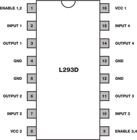
FIGURE 3-23 A pinout diagram of the L293D
- Now we’ll connect the grounds of the two power rails up. Connect the two ground rails on your breadboard by running a black M-M wire from one blue power rail to the other. This connects your Pi’s ground rail to your battery’s ground rail, as shown in Figure 3-24. We refer to connected grounds as the common ground.
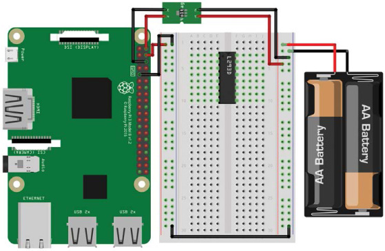
FIGURE 3-24 The L293D IC inserted into the breadboard with the Pi’s power rails connected
- Next use a wire to connect pin 16 (VCC 1) of your L293D to the 5 V positive power rail (the one connected to your Pi’s 5 V pin). This is the chip’s power supply. Once you have done this, connect the ground pins (GND) found on pins 4, 5, 12, and 13 of your L293D to the common ground. See the breadboard diagram in Figure 3-25 for guidance.
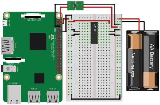
FIGURE 3-25 5 V power connected to the L293D and all four grounds wired up
NOTE
The length of your jumper wires can sometimes make them ungainly and cause your wiring to be confusing. If you got a variety pack of breadboard wires, you can use the shorter ones here to make the board neater. Alternatively, buy some single-core wire and cut and strip your own pieces to size.
- Now it’s time to connect the power for the motors, which will come directly out of your battery pack. Wire the positive +7 V to 9 V power rail connected to your battery pack to pin 8 (VCC 2) on your L293D. Instead of being the chip’s power supply, this time this is the motor’s power supply. Figure 3-26 shows this connection.
- The L293D has two Enable pins. If these aren’t on (in other words, if they are not receiving a high voltage), then any motor wired up to your L293D won’t respond to commands. To turn the Enable pins permanently on, connect pin 1 (Enable 1,2) and pin 9 (Enable 3,4) of your L293D to the positive power rail connected to 5 V on the Pi. I have used white wires in Figure 3-26 to show this step.
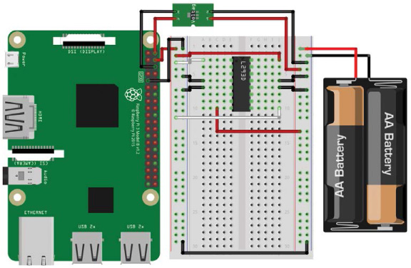
FIGURE 3-26 Connecting the L293D’s Enable pins to a high voltage by connecting them to the Pi’s 5 V power rail
Connecting the Motors
You can now wire up your motors to the L293D.
- Take one motor and connect one of its wires to pin 3 (Output 1) of your L293D chip, and the motor’s other wire to pin 6 (Output 2). Then take your second motor and connect the first of its two wires to pin 11 (Output 3) and the second to pin 14 (Output 4), as shown in Figure 3-27.
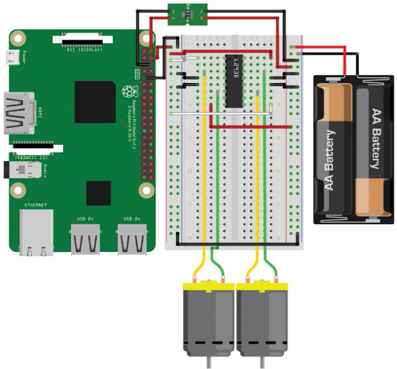
FIGURE 3-27 Both motors wired up to the outputs of the L293D
Finishing Up the Wiring
The last stage of the wiring process is to connect your Pi’s GPIO pins to the inputs for the L293D. Each motor requires two GPIO pins to function (I’ll cover how this works in the next chapter). This means that, in total, you need four GPIO pins to drive two motors.
- Use a M-F jumper wire to connect your Pi’s physical pin 11 (BCM 17) to pin 2 (Input 1) on your L293D. Then use another jumper wire to connect your Pi’s physical pin 12 (BCM 18) to pin 7 (Input 2) on your L293D. You have now successfully wired up one motor. At this stage, your breadboard should look like Figure 3-28, with the most recent additions being the pink wires.
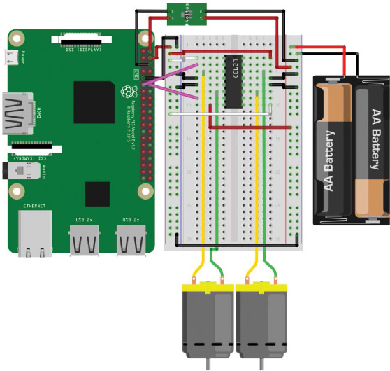
FIGURE 3-28 First motor’s input control pins wired from the Pi to the L293D
- Finally, you must wire up the GPIO pins for the second motor. Do this by connecting your Pi’s physical pin 13 (BCM 27) to pin 10 (Input 3) of your L293D with another jumper wire. Then connect your Pi’s physical pin 15 (BCM 22) to pin 15 (Input 4) of your L293D.
Congratulations! You have finished wiring up your motors and motor controller. Your breadboard should look like the diagram in Figure 3-29, which shows the last wires in purple. In addition, it shows a photo of my robot all wired up.
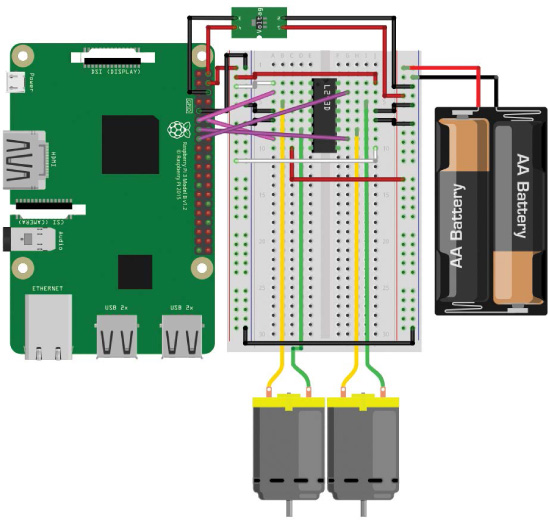
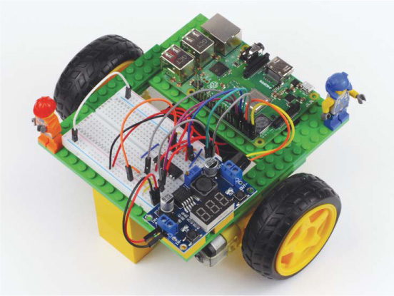
FIGURE 3-29 The completed circuit, with both motor’s inputs wired from Pi to L293D (top); the completed robot! (bottom)
You have the physical parts of your first robot finished. The next step is to program it to do cool stuff. As it is, you can program your robot to move around like a remote-controlled car. In the next chapter, we’ll add some code so you can do exactly that!
CUSTOMIZING YOUR ROBOT
Nothing is worse than a dull robot. Now that you have constructed your chassis and wired up your electronics, why not customize your creation?! Add some color! Spruce up your chassis! You may notice that I have a variety of LEGO minifigures riding around on mine.
SUMMARY
You have done a lot in this chapter! We have discussed why two-wheeled robots are great, their various elements, and the options you have for building them. I’ve shown you how to wire up your Pi, connect power, and attach your motors to build your very own robot from scratch.
With all of this fantastic groundwork in place, in the following chapter, I’ll guide you through the next exciting step: programming your robot and making it move!
As with any wiring, a little perseverance pays off! Before you proceed to the next chapter, quickly read through the instructions again to double-check that you have no short circuits and everything is connected as it is supposed to be. That way, you should have no problems getting your robot up and running in the next chapter.