Table of Contents for
Learn Robotics with Raspberry Pi
 Learn Robotics with Raspberry Pi
Published by
No Starch Press, 2018
Learn Robotics with Raspberry Pi
Published by
No Starch Press, 2018
- Cover Page
- Title Page
- Copyright Page
- Dedication
- CONTENTS
- CONTENTS IN DETAIL
- ACKNOWLEDGMENTS
- FOREWORD
- INTRODUCTION
- CHAPTER 1: GETTING UP AND RUNNING
- CHAPTER 2: ELECTRONICS BASICS
- CHAPTER 3: BUILDING YOUR ROBOT
- CHAPTER 4: MAKING YOUR ROBOT MOVE
- CHAPTER 5: AVOIDING OBSTACLES
- CHAPTER 6: CUSTOMIZING WITH LIGHTS AND SOUND
- CHAPTER 7: LINE FOLLOWING
- CHAPTER 8: COMPUTER VISION: FOLLOW A COLORED BALL
- NEXT STEPS
- RASPBERRY PI GPIO DIAGRAM
- RESISTOR GUIDE
- HOW TO SOLDER
- RUN PROGRAM ON STARTUP
- Learn Robotics with Raspberry Pi®: Build and Code Your Own Moving, Sensing, Thinking Robots
- Learn Robotics with Raspberry Pi®: Build and Code Your Own Moving, Sensing, Thinking Robots
2
ELECTRONICS BASICS
ELECTRONICS IS THE SCIENCE OF CONTROLLING AND MANIPULATING ELECTRICAL ENERGY TO DO SOMETHING USEFUL. IT’S ABOUT MAKING ELECTRONIC COMPONENTS LIKE LIGHTS, SENSORS, AND MOTORS DO EXACTLY WHAT YOU WANT THEM TO DO.
Many innovations stem from the different fields of electronics. Most interesting for us is the branch of robotics . To make your own robots, you’ll need to understand the basics of electronics and bend this knowledge to your will! In this chapter, I’ll give you your first taste of electronics in the form of two projects. You’ll program an LED (light-emitting diode) to blink at regular intervals, and then wire up a button to print a message to your terminal when it’s pressed. You’ll be blinking LEDs and controlling the physical world in no time at all!
WHAT IS ELECTRICITY?
Electricity is everywhere in our day-to-day lives: electric currents are used to power electrical components and appliances, like the lights in your house, your TV screen, your toaster, and the motors of a Raspberry Pi robot. But what actually is electricity?
Electricity starts with atoms. Everything in the world is made out of billions of tiny atoms—even you! And as you may have learned in science class, atoms themselves are composed of three particles: protons, neutrons, and electrons. The protons and neutrons sit together in the center of the atom to form the atom’s nucleus, and the electrons orbit that nucleus, as shown in Figure 2-1.
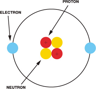
FIGURE 2-1 A diagram of an atom
Protons and electrons each have electric charge, which is a fundamental property of matter. Protons are positively charged, and electrons are negatively charged. Neutrons have no charge; that is, they are neutral. You may have heard the saying “opposites attract,” and that applies here. Because protons and electrons have opposite charges, they are attracted to each other and stay together, forming the atoms that make up everything around you.
Atoms come in many different arrangements called elements. Each element is defined by the number of protons, electrons, and neutrons each atom contains. For example, the element copper usually has 29 protons and 35 neutrons, while gold has 79 protons and 118 neutrons. All metals, like copper, gold, and iron, are made out of collections of atoms all pressed up against each other. Some of these materials are conductive, which means that, when given energy, the electrons from one atom can move to the next atom. This causes a flow of charge in the material, known as an electric current. The number of electrons flowing through a point in a material at any given second is the size of the electric current, which is measured in amperes (A).
For an electric current to flow, there must be a complete circuit. A circuit is a closed path, like a loop, around which an electric current moves. The circuit must be made of conductive material for the electricity to move through, and any gap in the circuit means the electricity cannot flow.
The circuit needs a source of energy to “push” the electric current around. This can be a battery, a solar panel, electrical mains, or any number of things. Crucially, these sources provide a potential difference, known as a voltage. A voltage simply pushes electrons through a conductor, such as copper wire, and the strength of a voltage is measured in volts (V).
Power sources have a positive and negative terminal. In a simple circuit, like the one shown in Figure 2-2, the terminals of a battery could be connected by a thick copper wire. Electrons are negatively charged and are therefore attracted to the positive terminal of the battery, so they travel through the circuit from the negative end to the positive end, pushed along by the voltage.
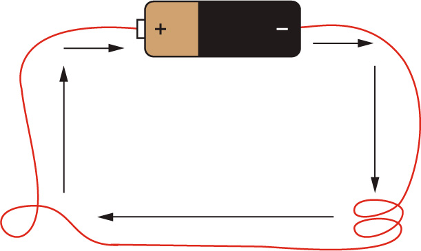
FIGURE 2-2 A circuit showing the flow of charge around a thick wire connected to the positive and negative terminals of a battery
Although the electrons flow from negative to positive, it is convention to think of the current flowing from positive to negative. The battery in this circuit has a fixed voltage. If this voltage is increased, more electrons would be pushed around the circuit and the current would be larger. Conversely, if this voltage is decreased, fewer electrons would be pushed around the circuit and the current would be smaller.
Resistance
Now that you have an understanding of circuits, we need to add another ingredient into the mix: resistance. Resistance simply reduces current. Outside the laboratory every material has some amount of resistance, which is measured in ohms (Ω). One way to think about resistance is to imagine a water pipe. The water flowing through the pipe is like electric current flowing through a copper wire. Imagine the water pipe has one end higher than the other. The water at the higher end of the pipe has more energy (potential energy) than water at the lower end. If the pipe is level, no water will flow. If the pipe is slightly sloping, a small flow will occur. The actual amount that flows depends on both the difference in height of the ends above ground and how wide the pipe is. The height difference of the pipe is like potential difference, or voltage.
Resistance, on the other hand, is like something squeezing the pipe and affecting how wide it is: the more it is squeezed, the less water is able to flow through it (see Figure 2-3). This translates to less electric current flowing through the circuit.
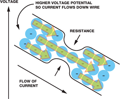
FIGURE 2-3 Resistance reduces the amount of current that can flow through a circuit.
Therefore, three ingredients make up an electric circuit: voltage, current, and resistance. They all seem to be pretty closely connected, right? You may even think that there must be a certain mathematical connection or law relating to them—and you’d be right.
Ohm’s Law of Electricity
Ohm’s law deals with the relationship between voltage, current, and resistance. It states that the voltage across a conductor is proportional to the current running through it.
Let’s break this down to see what it means. In a circuit, voltage is simply equal to current multiplied by resistance. We use V to stand for voltage, I for current, and R for resistance. So, the equation for voltage is written as follows:

As with any mathematical equation, you can rearrange it to work out the equations for the other terms. For example, from Ohm’s law we know that the current in a circuit is equal to the voltage divided by the resistance. When you rearrange the equation for current and resistance, you get the following equations:

R = 
If all of this is a little confusing, don’t worry! As you make your own circuits, it will become easier to understand. Now that we have covered some of the basics of electricity and electronics, let’s get making!
MAKING AN LED BLINK: RASPBERRY PI GPIO OUTPUT
Just as “Hello, world!” is a traditional first program, making an LED blink is a traditional first electronics project since it very neatly demonstrates using the GPIO pins as outputs. This project will be your introduction to using your Pi’s GPIO pins. Before we begin, you might have some questions.
First, what is an LED? Short for light-emitting diode, an LED is a component that gives off light when an electric current is passed through it. LEDs are the modern equivalent of an old light bulb, but they use less power, don’t get hot, and have a longer life.
The Parts List
For your first foray into electronics, you’re going to need a few extra things besides the Raspberry Pi you set up previously. Here’s what you’ll need for this project:
NOTE
For guidance about where to buy and source these parts, check the Introduction.
- A breadboard
- An LED (color of your choice)
- An appropriate resistor
- Jumper wires
Before we wire these components up, I’ll explain a little more about how they work and why you need them.
Breadboard
An electronics breadboard allows you to connect electronic components without having to fuse them together permanently (something that is called soldering; see “How to Solder” on page 204). This means you can quickly prototype circuits by inserting components into a breadboard’s holes. The space between the holes of a breadboard is standardized (2.54 mm/0.1 inches), so all breadboard-friendly components should fit with no trouble. Breadboards come in several sizes with different numbers of holes (also known as points). I would recommend a 400-point breadboard, like the one in Figure 2-4.
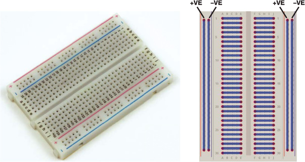
FIGURE 2-4 A 400-point breadboard and a diagram of how the rows and columns are connected to each other
You can see in Figure 2-4 how the rows and columns of the breadboard are internally connected with metal strips. So, if you put one component into a row and put something else into the same row, for example, they will be connected in a circuit.
LEDs
LEDs come in all different shapes, sizes, and colors. Fortunately, they are also incredibly cheap. When bought in bulk they are quite literally pennies each. Make sure that your LED has two legs that can be arranged to fit in your breadboard, as shown in Figure 2-5.

FIGURE 2-5 A blue LED
Feel free to buy an LED in any color you wish—I have gone for blue. Make sure to check the voltage specification for the LED you buy. You need to make sure that the voltage required to light up the LED is less than 3.3 V. This is often referred to as the forward voltage. You can usually find this information in the online listing for your LED. The forward voltage of my LED is 2.5 V. The Raspberry Pi’s GPIO pins work at 3.3 V, so if your LED has a forward voltage of 5 V, for example, your Pi won’t be able to light it up!
You also need to find out the forward current of your LED. The forward current is the recommended current to run through your component. My LED has a recommended forward current of 30 mA (milliamps are one thousandth of an amp), which is the equivalent of 0.03 A. If you provide less current than recommended, your LED won’t be very bright; if you provide too much current, it might blow up (you’ll hear a small pop when this happens). This information will also most likely be in the LED’s internet listing or packaging. If you aren’t sure about the specifics of your LED, don’t worry—small, cheap ones are usually just fine for our use. If you have no information about your LED, just assume that the forward voltage is around 2 V and the forward current is about 20 mA.
Resistors
To avoid overloading our LEDs, we’ll use a resistor. Every material has resistance, but resistor components are designed specifically to create pure resistance in circuits.
LEDs, and most components, are quite sensitive to the amount of current that flows through them. If you were to connect an LED directly to a battery and create a circuit without a resistor, the amount of current that would flow through the LED could be large enough to cause it to overheat. A resistor lowers the current through the LED to prevent this from happening.
Resistors come in different values denoted by colored bands, which you can see in Figure 2-6. Take a look at the resistor guide on page 202 to learn what these bands mean and how to read them.

FIGURE 2-6 A resistor
To find out what resistor you need, you’ll have to apply Ohm’s law! From the equation you saw earlier, you know that resistance is equal to the voltage divided by the current, or R = V/I. In our case, the voltage is the difference between the voltage the Pi supplies, 3.3 V, and the forward voltage of the LED: it is the total source volts minus the LED volts. For me, that is 3.3 V – 3 V = 0.3 V. You should use your forward voltage here instead, or 2 V if you don’t know it.
The current is the forward current of your LED. For me that is 0.03 A. Make sure that this value is in amps, not milliamps!
NOTE
I recommend buying a selection of resistors, which are normally organized into something that looks like a book. That way, you’ll have a resistor for every occasion and won’t have to buy them individually.
I can work out the value of the resistor I need to lower the current to 0.03 A by simply calculating the following equation: 0.3 / 0.03 = 10. This means that I will need a resistor of approximately 10 Ω. Often you won’t be able to find a resistor value for the specific number you’ve calculated. That’s okay: in most cases, you can simply use the nearest valued resistor you can find. For my LED I was lucky and had a resistor that matched the value I needed exactly. I am using the 10 Ω resistor pictured in Figure 2-6.
If you’re still unsure about the forward voltage and forward current of your LED, just err on the side of caution and fit a sensibly large resistor of at least 100 Ω into your circuit. If the LED is too dim, downsize the resistor until you get to a suitable level of brightness (dim enough to not hurt your eyes is a good rule of thumb). Don’t try to do this the other way around: you can’t unexplode an LED!
Jumper Wires
Finally, you’ll need some wires to connect everything up. Specifically, you’ll need jumper wires, which are breadboard-friendly wires that allow you to connect things to the Pi’s GPIO pins. You can see some examples of jumper wires in Figure 2-7.

FIGURE 2-7 A collection of jumper wires
The ends of jumper wires are either male or female. A male end (often abbreviated as M) has a wire sticking out of it that you can insert into a breadboard’s holes. A female end (abbreviated as F) instead has a hole into which you place a wire. I would recommend buying a variety so that you have a jumper wire for all situations. We’ll be using a lot of these throughout the book! In Figure 2-7, you can see my collection of M-M, M-F, and F-F jumper wires. For making an LED blink, we’ll need two M-F jumper wires.
Wiring Up Your LED
Now that you’ve collected your parts, it’s time to wire up your LED and create your first circuit! You’ll wire up your circuit as shown in Figure 2-8, so you can use this diagram as a reference as you go through the instructions.
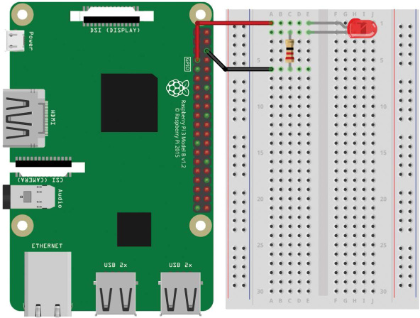
FIGURE 2-8 Breadboard diagram for wiring up an LED
Depending on the breadboard you have, your circuit may look slightly different. To make sure your connections are correct, follow these instructions:
- Insert the LED into the breadboard so that each leg is in a different row. If you put the LED’s legs into the same row, they’ll be connected to each other, but won’t be connected to anything else. LEDs have a positive and negative side, which you need to align with the flow of the current. The long leg of the LED is the positive side—called the anode. The short leg is the negative side—the cathode. The LED bulb will usually be flat on the side of the cathode as an extra indicator.
- Insert one leg of your resistor into the same row on the breadboard as your LED’s shorter leg. Putting the resistor leg in the same row as your LED connects the two in a circuit. Connect the other leg of the resistor to any of the other points of the board.
- Now, with your Raspberry Pi turned off, insert the male end of one of your M-F jumper wires into the breadboard, in the same row as the long leg of your LED. Locate physical pin 7 on your Raspberry Pi, also known as the GPIO/BCM 4 pin (see “Raspberry Pi GPIO Diagram” on page 200 for an image of this), and connect the female end of the wire to it.
THE VARIOUS NAMES OF GPIO PINS
The Raspberry Pi’s GPIO pins can have several names. First, you can refer to the pins from their physical numbers—that is, how they are laid out. However, the processor on the Raspberry Pi does not understand this numbering and has its own name for the GPIO pins, sometimes referred to as the BCM numbering of the pins. In our case, you have wired up your LED to physical pin 7: that’s BCM pin 4! See “Raspberry Pi GPIO Diagram” on page 200 for a diagram of the GPIO pins and some further explanation.
- Finally, insert the male end of your other M-F jumper wire into the row of the breadboard that contains only one leg of the resistor and none of the LED’s legs. Then connect the female end to physical pin 6 on your Raspberry Pi. This is one of the ground pins. You can think of ground as the negative terminal of a battery. It is just the lower side of a voltage.
Programming Your Raspberry Pi to Blink Your LED
NOTE
When you power on your Raspberry Pi, your LED may be off, on, or even dimly lit. Don’t worry! Your LED is fine in any of these states. You haven’t yet instructed the pin to be a certain state, so your pin isn’t quite sure what to do yet.
You should now have your circuit wired up, so boot up your Raspberry Pi and log in. It’s time to write a program to blink that LED!
From the terminal, navigate from the home directory into the folder you created in Chapter 1 with the command:
pi@raspberrypi:~ $ cd robot
Now you’ll create a new file and write a Python program to control your LED. Pick whatever name you like for your file, but ensure your filename ends with .py. I’ve called mine blink.py. The following command creates a new file and opens the Nano text editor:
pi@raspberrypi:~/robot $ nano blink.py
You’ll now find yourself in a Nano text editor identical to the one you came across in Chapter 1.
Enter the code in Listing 2-1 to instruct your LED to flash on and off (the numbers in circles don’t actually appear in the program, but we’ll be using them for reference).
➊ import gpiozero
import time
➋ led = gpiozero.LED(4)
➌ while True:
➍ led.on()
➎ time.sleep(1)
➏ led.off()
➐ time.sleep(1)
LISTING 2-1 Program to blink an LED
This eight-line Python program is easy to understand when you look at it one line at a time, so let’s break it down.
Python is an interpreted programming language, meaning when this code is run, your Raspberry Pi (or any other computer) will execute your program line by line, starting at the top and moving down in a logical manner. That means the order of your code matters.
Python comes with all sorts of built-in abilities. For example, in Chapter 1 you printed text to the terminal, a capability Python has by default. There are hundreds of other things Python can do, but some abilities need to be imported from external sources. For example, Python is not able to control your Pi’s GPIO pins on its own, so we import a library called GPIO Zero ➊. In programming, a library is a collection of functions a program can use. By importing a library, we bring these functions into the current program for our own use. The GPIO Zero library was created by the Raspberry Pi Foundation to give programmers a simple GPIO interface in Python. Importing this library enables your program to control your Pi’s GPIO pins! Note that it’s actually called gpiozero in the programming language, though, as we can’t include spaces in library names and the convention is to use lowercase.
On the next line we import the time library, which allows your Python program to control timings. For example, you’ll be able to pause the code, which will be very useful in our case!
Next, we make a variable ➋. In programming, variables are names used to store information to be referenced and manipulated in a program. They provide a way of labeling data, and they make code simpler, easier to understand, and more efficient.
In this case, we’ve created a variable called led that references the LED software from the GPIO Zero library. We give the LED() function the value 4 in parentheses to show that we are referring to an LED on GPIO/BCM pin 4. When we call led later in the program, the Pi knows we mean this pin.
Then we begin a while loop ➌, which is a conditional statement that will keep running the code inside it until the condition is no longer met. In simple English, we’re telling the loop: while this condition is true, keep running the code. In this case, the condition is simply True. The True condition will always be true and will never be false, so the while loop will go around and around indefinitely. This is useful to us, as we’ll be able to write the code to make the LED flash once, and the loop will take care of making the LED flash over and over again.
Within the while loop, you also come across a key structural feature of Python: indentation. Python knows that all the code indented by the same number of spaces belongs to the same group of code, known as a block. The four lines following the while loop are indented four spaces each; as long as the condition is true, the loop will run that whole block of code.
You can create indentation in different ways. Some people use two spaces, four spaces, or a TAB. You can use any method you like as long as you stay consistent throughout your Python program. I’m a TAB person myself.
At ➍, you switch the LED on using the command led.on(). Remember that led refers to the pin we connected the LED to and now we’re telling that pin to be “on.” The dot (.) separates the thing we’re talking about, in this case the LED, from what we’re asking it to do, in this case be turned on. Turning on a GPIO pin is also known as bringing that pin high, since the Raspberry Pi will apply a voltage of 3.3 V across your circuit when this line of code runs.
Next we use a sleep() statement ➎ to tell your program to pause for whatever number of seconds you give to it in parentheses. In this case, we entered a value of 1, so the program sleeps for just 1 second. After this, you switch the LED off using the command led.off() ➏. Repeat the sleep() statement at ➐ to make the program wait for another second before looping back around again to the start of the while loop. This sequence of on-wait-off-wait continues indefinitely.
Once you’ve finished entering the code for your program, you can exit the Nano text editor and save your work. To do this, press CTRL-X. You will then be asked whether you would like to save the changes you have made. Press the Y key to say yes. Nano will then prompt you for the filename you would like to write to, which in our case should be blink.py or the filename you entered when you opened the Nano editor. Press ENTER to confirm the filename.
Running Your Program: Make Your LED Blink
Now that you understand how your program works, it’s time to run it. You’ll follow the same process to execute your program as you did for the helloworld.py program you created in Chapter 1. Enter the following code into the Raspberry Pi’s prompt:
pi@raspberrypi:~/robot $ python3 blink.py
Your LED should now start to blink on and off at regular intervals (see Figure 2-9). Congratulations, you’ve just successfully interfaced your Raspberry Pi with the outside world!
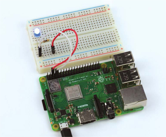
FIGURE 2-9 A happily blinking LED connected to the Raspberry Pi
To kill your program and stop the blinking LED, press CTRL-C.
TROUBLESHOOTING GUIDE: WHY ISN’T THE LED BLINKING?
If your LED isn’t blinking, don’t panic. You can likely fix your circuit with a little troubleshooting. First, check whether your LED is inserted with the legs the right way around. Because LEDs are a form of diode, current flows through them only in one direction, so if you have your LED in the wrong way it won’t light up! Instead, it’ll just do nothing. Go back to the instructions and make sure you followed them accurately.
If this doesn’t fix your problem, check the rest of your circuit. Is everything connected properly? Are all of the wires firmly in place? Check that you have wired up your circuit to the correct pins of your Pi’s GPIO port—this is an easy mistake to make!
If you’re convinced that your circuit is sound and your LED and resistor are appropriate (as explained in the parts list), then you may have a software issue. When you ran the program, did it crash? Did you get an error message? You may have made an error when copying the code from this book. Go back and check, or grab the code files from https://nostarch.com/raspirobots/ and run the blink.py file from there instead.
The GPIO Zero library is included by default in all new Raspbian releases, but if you are running an older version of Raspbian, you may need to install the library manually. To do this, enter the command:
pi@raspberrypi:~/robot $ sudo apt-get update
followed by the command:
pi@raspberrypi:~/robot $ sudo apt-get install python3-gpiozero python-gpiozero
Challenge Yourself: Change the Timing
Take a look at the code you used to make your LED blink. What would happen if you modified some of it? For example, you could experiment by changing the timing of the sleep() statements and seeing what different patterns you can make! Play around a bit to see what effects your changes have.
NOTE
If you want to shut down your Raspberry Pi, you should do so safely in software before yanking out the power cord. To commence a power down sequence, use the command sudo shutdown now. Wait a few seconds before pulling out the power cord. Or, choose the shutdown option in the main menu from the GUI if you’re using a directly connected screen.
INPUT FROM A BUTTON: RASPBERRY PI GPIO INPUT
Blinking an LED is the perfect first experiment for the world of electronics and physical computing with your Raspberry Pi, but it demonstrates only the output aspect of what the Pi’s GPIO pins can do. GPIO pins can also take input, meaning they can take data from the outside world and react to it. In this section you’ll wire a button up to your Raspberry Pi and write a program that is triggered whenever that button is pressed.
Explaining the Parts List
The projects in this book build upon each other, so in addition to your Raspberry Pi and breadboard, for this project you’ll need a button and two M-F jumper wires.
Buttons come in hundreds of different shapes, sizes, and varieties. For this project, you’ll need to acquire a breadboard-friendly momentary push button, like the one shown in Figure 2-10.
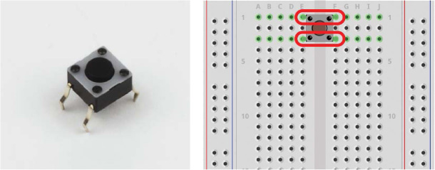
FIGURE 2-10 A four-legged momentary push button and a diagram of the leg pairs
Buttons are often referred to as switches, and most have either two or four legs that connect to the points of a breadboard. The function of a momentary switch is simple: when the button is pressed, the contacts inside the button join together and complete the circuit. When the button is released, the contacts inside are separated, so the circuit is incomplete and no current flows. That means your circuit is connected only while the button is pressed; that’s why it’s called “momentary”!
For buttons with two legs, it’s obvious that when the button is pressed both sides are connected. For buttons with four legs, it’s a little bit more complicated. The legs are set up in pairs, so you only actually need to worry about two of them. Usually, opposite legs, like the ones indicated in Figure 2-10, are coupled, which means only one leg of each pair needs to be connected to the circuit. If you are unsure of which legs are pairs, check your button’s specification.
Wiring Up Your Button
With your parts ready, you can now wire up your button. Use the breadboard diagram in Figure 2-11 as a reference.
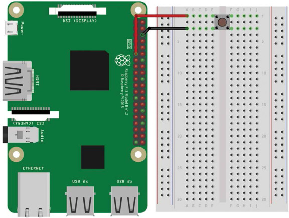
FIGURE 2-11 Breadboard diagram for wiring up a button
If you’ve just finished the previous project and still have an LED wired up to your Pi, feel free to take the circuit apart or wire up your button on a different part of your breadboard—just make sure that you use different rows of the breadboard for each project. Once you’re ready to set up your next circuit, follow these instructions:
- Insert your push button into your breadboard and ensure that each leg is in its own row. You’ll need to insert the button with two legs on either side of the row divider in the middle of your breadboard to accomplish this.
- With your Raspberry Pi turned off, use a jumper wire to connect one leg on one side of the divider to the ground pin on your Raspberry Pi (physical pin 6).
- Use another jumper wire to connect the other leg on the same side of the divider to pin 11 (BCM pin 17) on your Raspberry Pi. Check the pinout on page 201 if you’re not sure which pin is which.
With your Pi setup like mine in Figure 2-12, you now need to write a program to take input from the button when it is pressed.
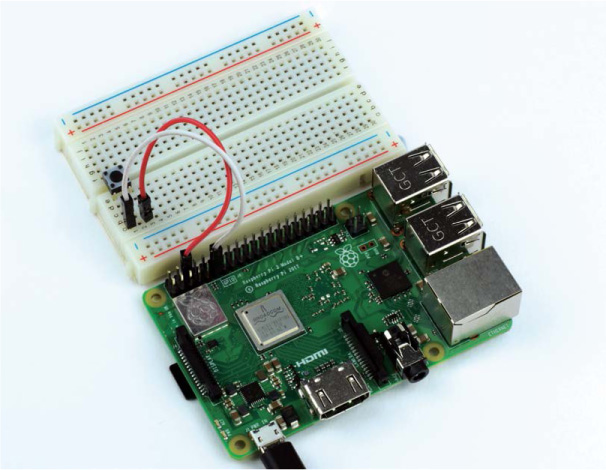
FIGURE 2-12 The complete button and breadboard setup
WARNING
Once you are finished, you should have a circuit set up like the one shown in Figure 2-11. Take care that the wiring is correct. There is very little resistance in the switch and it will electrically connect two things very closely. A wrong connection can be dangerous to your Pi!
Programming Your Raspberry Pi to Display Input from Your Button
From the terminal, make sure you’re in the folder you created in Chapter 1. If you just completed the previous mini-project you most likely already are, but if not, just navigate from the home directory into the robot directory with this command:
pi@raspberrypi:~ $ cd robot
Now create a new Python program to get input from your button in Nano. I’ve created one and called it button.py as follows:
pi@raspberrypi:~ $ cd robot
You’ll find yourself in a familiar blank Nano interface. Enter the code in Listing 2-2 to get your button working.
➊ import gpiozero
➋ button = gpiozero.Button(17)
while True:
➌ if button.is_pressed:
➍ print("Button is pressed!")
➎ else:
print("Button is not pressed!")
LISTING 2-2 A program to take input from the button
We import the GPIO Zero library in exactly the same way as we did for the blinking LED project ➊. All of the electronics projects in this book will use this library, so you can expect to see this line in all the programs in this book!
We then create a variable called button ➋, assigning some button software from the GPIO Zero library to that variable and making sure to specify in the parentheses that the button is connected to BCM pin 17.
We then start a while loop as we did in our LED program, but unlike our previous program, the first line in this block starts an if/else statement. In programming, if statements are conditional statements that activate some code when a condition is satisfied. Our if statement almost directly translates into English as “if the button is pressed, do the following” ➌. While the if statement is true, the indented line ➍ is executed and a string of text is printed to the terminal, telling us the button has been pressed.
Usually, but not always, when there is a conditional if statement, there is often an else statement, because if the button isn’t pressed, something else must happen! The else statement ➎ can be translated into English as “if anything else, do the following.” The indented block of code following the else statement is then executed and prints to the terminal that the button hasn’t been pressed.
Because the if/else statements are in a while loop whose condition is True, the code continues to run forever unless the program is stopped. Once you have finished entering your program, you can exit the Nano text editor as usual: press CTRL+X, save the changes you have made by pressing the Y key at the prompt and then press ENTER to confirm the filename as button.py.
Running Your Program: Get Input from Your Button
To run your program, simply enter the following into the terminal:
pi@raspberrypi:~/robot $ python3 button.py
You should now see the statement Button is not pressed! repeatedly in the terminal. When you press your button, the statement Button is pressed! should be printed to your terminal.
pi@raspberrypi:~/robot $ python3 button.py
Button is not pressed!
Button is not pressed!
Button is pressed!
TROUBLESHOOTING GUIDE: WHY ISN’T THE BUTTON WORKING?
Just as in the previous mini-project, if your button isn’t working, don’t worry! First, check your circuit. Is everything wired up correctly? Are the wires firmly in the breadboard? Have you connected your button in the right way? If your switch is slightly different from my model, have you looked into the details of how it is different? If you think that your circuit is okay, you may have made an error when copying the code from this book. Go back and check, or grab the code files from https://nostarch.com/raspirobots/.
To kill your program, press CTRL-C.
Challenge Yourself: Combine Your Button and LED Programs
See if you can combine both of the mini-projects in this chapter. Try to create a program that flashes an LED when the button is held down, or a program that keeps the LED turned on until the button is pressed.
SUMMARY
In this chapter you’ve had your first taste of electronics in the form of two mini-projects. You’ve learned a lot of theory and fundamentals, all of which are going to come in handy as you build your robot over the next chapters. I’ve also introduced some key programming techniques and concepts—we’ll be using plenty of if/else statements and loops in the future.
In the next chapter I’ll guide you through the process of making your first robot. We’ll cover the materials and tools you’ll need as well as the construction process itself.