
Creating a scalable architecture is not just about drawing boxes on a whiteboard and then connecting them with black lines. There is usually a method to the madness, and in this chapter I’ll show you some of the common patterns used in creating a professionally designed system.
In other words, I will provide you with a building block for your next big project, and even if none of the examples presented here exactly suits your needs, you’ll be able to solve your problems using the tools you picked up in this chapter.
The Patterns
The IT field is filled with patterns, which is funny if you think about it, because we usually take pride in the way our work is so much like a work of art, where imagination plays such a big role. Little does everyone else know that in fact, we’re just using tried and tested patterns and adding little changes to make them work for us.
Yes, it’s true, every once in a while, there comes a new da Vinci and blows our mind with a completely new and original pattern. It can happen, and it will happen, but in the meantime, the rest of us can take pride in our originality while we blindly follow the work of others.
And please, don’t take this the wrong way. This is exactly what we should be doing. We’re not paid to reinvent the wheel every day, in fact, we’re paid to solve problems in the most efficient way, and what’s more efficient than re-using someone else’s solution if it fits our needs? Literally nothing.
So without further ado, let’s start getting our hands dirty with the different architectural patterns I’m going to cover in this chapter.
Layered Architecture
Each layer must have a well-defined purpose (presentation layer, business layer, and so on).
Each layer cannot speak (or send data) to any other layer that is not the one directly below it
Tip
In most publications, the terms layer and tier are used interchangeably, but in practice they refer to two different topics. Layers are logical groupings of your code, while tiers refer to physical instances (that is, servers) where the code resides. This is relevant, because you could perfectly well have a 3-layered architecture that is deployed into a single tier (your developer’s workstation).
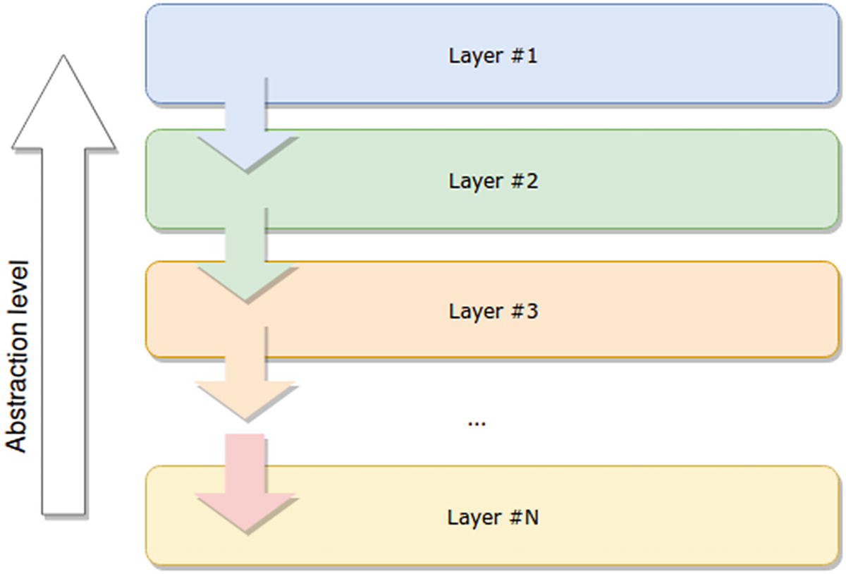
N-layer architecture example, showing how data flows from one layer to the next
Note
The data-flow refers specifically to the way communication is initiated, not necessarily how actual data is transmitted; otherwise, this would imply there would never be any output to the user (since any action initiated at the interface layer could never return back to it to display the result).
One common misconception about this pattern is that people confuse it with MVC (Model-View-Controller), thinking the latter to be the 3-tier version of this one. In the next pattern, I’ll go over the main differences between the two.
As a side-effect of using a layered architecture, the code inside a layer is all related to the same functionality (or at least, follows a set of standards common to the rest). This in turn helps developers work independently from each other on different layers. This allows the teams to make internal changes to the layers without affecting anything else (as long as the actual interface remains the same).
You usually have your storage or persistence layer at the bottom of your diagram. This layer takes care of encapsulating everything related to the interaction with your storage. Encapsulation helps in many ways, such as making it easier to switch from one storage medium to the other, without affecting other parts of the application, such as the business logic or the UI.
On top of the storage, you usually have your business logic layer. This is where the business knowledge resides. Whatever makes the application tick goes in here.
Finally, on top of the previous one, you’ll have your UI layer. This is the client-facing front end and the main source of interactions and data for the rest of the platform.
Some people also split the business layer into two, one in which the business knowledge remains, and another, often called the application layer, which owns the interaction logic between the UI and the business layer and also provides some common services useful for that interaction.
MVC Is Not Layered
If you’ve been doing any kind of web development for the last few years, you’ve probably heard or read about Model-View-Controller (MVC) . This pattern is one that many web frameworks have adopted (Ruby on Rails, Django, and Sails.js, to name a few), because the structure of most web projects resembles this approach.
That is, in most web projects you have a UI (or View); you most likely will want to handle the requests of your UI somewhere (the Controller); and finally, you most likely have a storage engine, inside of which you can probably force your data to fit into a set of Models that represent your resources. You’ll also want to perform some transformations on this.
The model is the boss: here’s where the domain knowledge or business logic is stored, here is where the actual data is handled, and here is where all the business specific coding should take place.
The view is a simple representation of the model; there can even be several views for the same model. Remember that “representation” doesn’t mean “web page”; it means anything that can be read and understood by another system. A JSON object can be a view; this pattern could be applied to RESTful APIs just as much as it could be implemented to the front-end architecture of your very complex SPA.
Finally, the controller is the poor guy who drew the short stick and is in charge of interconnecting the model and the view. It basically takes input from the view and passes it along to the model, while executing whatever command is needed on that input. Then, once the controller gets something back from the model, it sends it back to the view, updating it. In some cases, the controller can even avoid the last part (as seen in Figure 2-2), letting the model directly update the view.
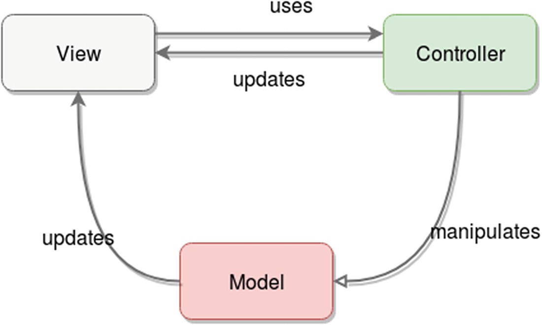
The interaction between nodes/objects in an MVC architecture
We now have enough information to answer the question of how this is different from a 3-layered architecture. You have seen that the layered architectural pattern does not allow jumping layers when sending messages between them. You could say that for the n-tier architecture, the communication is completely linear (it needs to go through all intermediate layers in all cases), while for the MVC pattern, you can work around that (as seen in Figure 2-2), since it is more of a triangular setup. This flexibility can potentially be a negative for this pattern if performance is a big concern, since every extra layer that you add to it will definitely add latency to the communication (no matter how fast you make it work).
Finally, I want to mention some of the variations on this pattern. Over the years, many adaptations have been created to improve on it, depending on whether the goal is to have less component coupling, better testing capabilities, or simply to follow a similar logic but adapted to particular needs. For instance, the MVP (Model, View, Presenter) pattern aims to remove that (normally) unwanted interaction between Model and View, making the Presenter the sole man-in-the-middle taking care of passing information between its associated View (there is only one view for each presenter) and it’s Model. Another very common variation is the MVVM pattern (Model, View, ViewModel), which aims for a two-way data binding between the View and ViewModel. This in turns allows for automatic updates on the view, based on changes in the model.
Client-Server
The client-server pattern is a very simple yet powerful one. It consists of having a powerful server that provides meaningful services to many clients.
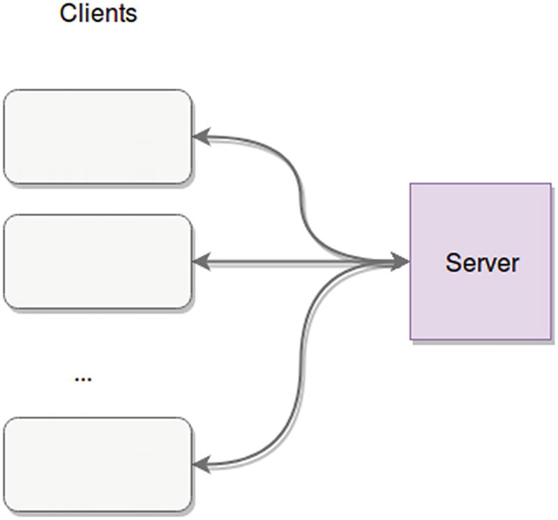
Client-server architecture
- 1.
Clients always start the conversation. After that initial step, depending on the communication protocol/technology, the conversation between both sides might vary. For example, in HTTP the server will only be able to send back a response to specific requests from the client. If you’re working with sockets, however, your server will be able to send messages to the clients that are not responses.
- 2.
The servers are always listening for new connections from clients to start a new conversation.
This pattern favors the off-loading of application logic into the server, where more hardware resources can easily be allocated. It also keeps the clients “thin” and “dumb,” in the sense that they usually don’t have a lot of business logic knowledge; instead, they simply know what to request from the server, and it is in the latter where all the heavy business-related computation will take place.
One of the main benefits of this approach is that making changes and fixes to either side does not necessarily mean affecting the other. That is, fixing a server bug doesn’t mean you need to even touch the client code, and vice-versa. Inherent security is another plus that comes out of this setup, since any core security check can be done on the server side, making sure any clients that are tampered with can still remain secure. (Think of a multiplayer game client, for example, where hackers can modify a player’s position; if the server is still checking for that, then the modification has no effect.) The clear separation of concerns between client and server is what give you that ability.
Another benefit from thin and dumb clients is that they’re easier to distribute (you don’t need a 2GB client when a simple 10MB will do, and you can keep the rest of the 2GB code in the server).
Finally, consider that even though Figure 2-3 shows a single server dealing with all the clients (essentially representing a monolithic approach), your server “box” can actually be expanded into a set of microservices or any other distributed architecture you might find more useful, where there is a single point of contact between dumb clients and business logic.
In fact, if you think about it, doing that you could very well end-up with a layered pattern, in which every layer is usually a different tier (physically separated from each other). As long as your client and server layers are physically separated, your client-server architecture is essentially a 2-tier one, in which the two constraints described earlier apply.
Master-Slave
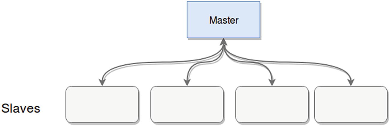
Master-slave architecture example
Any behavior-affecting messages are one-way, from the master to the slaves. Slaves don’t have the ability to affect the master.
Not all slaves need to work on the same tasks; in fact, usually this is a way to offload heavy work into multiple nodes, maintaining a single point of contact with clients of the architecture.
Some versions of this pattern allow slaves to elect one of their own as a new master, if the current master is no longer working.
Database architecture. Most databases provide a version of this pattern; some of them use it to increase processing power, and others use it to provide high availability in case of a problem with their master nodes. For the latter case, slave nodes are in charge of keeping track of the master’s data and staying in-sync with it to minimize the effect of a crash in the master.
Increased parallel processing capacity. Hadoop, for example, uses a master-slave approach to dealing with its task tracker nodes. The master in this case is the JobTracker, which takes care of orchestrating and keeping tabs on the slave task trackers.
Tip
In retrospect, this pattern is one you can use to improve a monolithic client-server architecture, by breaking up your server into a master-slave pattern (obviously this only applies if your server works in this way, but if you were developing a database engine, it would be a good pattern to follow).
Event-Bus or Event-Driven Architectures
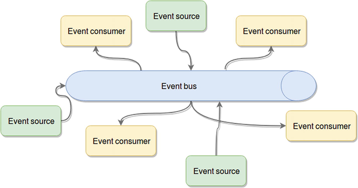
Event-driven architecture
Event sources: These are the components that generate events and publish them into the event bus.
Event consumers: The consumers are the components that are expecting a particular set of events and are ready to react to them once received.
Event bus: The channel (or channels, since having multiple ones might help keep things logically separate and provide separation of concerns) through which the events will be distributed (sent from the sources to the consumers). For best results, you’ll want an event bus that is capable of scaling easily and that ensures at least high availability if not fault tolerance to minimize loss of events during a problem.
The actual event: Although not represented in the diagram, this is just data, in the format you want, containing the information you want. It’s usually a good idea for this piece to be serializable, in order to allow it to easily be transmitted through the event bus.
This pattern is extremely powerful for providing a highly available platform, or even when trying to scale up—as long as your architecture follows the guidelines of the diagram in Figure 2-5. In other words, you need to avoid component-to-component communication and allow them to interact with each other only through the event bus.
If you do that, you can potentially replace crashed nodes with new instances in the time it takes them to boot up. The same happens if you need more processing power; you simply add new consumer or sources and connect them to the event bus, and that’s all.
A good idea when dealing with this type of architecture is to use a third-party data bus (as long as that’s an option), because that will allow you to focus on creating the event sources and event consumers, while at the same time using a tried-and-tested bus, one that can reliably transmit the data and scale when needed.
A classic example of this approach consists of using a message queue as the event bus. In this case you wouldn’t want to create your own bus; you would most likely want to use one of the many existing solutions such as RabbitMQ, Kafka, ZeroMQ or any other.
“With great power comes great chance of having errors.”
Because of the asynchronous nature of the event bus and the event-driven reactions, your platform must also be able to function asynchronously; otherwise it will not work for you.
Testing a logic bug on this setup is also quite challenging. You have to trace the path of the event data from one component to the other, and if the event is transformed by the actions of one of the consumers, it’s even worse.
Error handling can also be a challenge—especially if you don’t standardize that across your platform.
Another potential problem, one that is especially likely if you have a lot of components and a big team working on them, is to maintain a standard message protocol across your platform.
Microservices Architecture
This pattern is one of the best-known , since it’s been growing in popularity in the last few years. Everybody and their mother is jumping into the microservices bandwagon, whether they have use for them or not. Just like with anything in our industry, there is no silver bullet solution; so hoping that microservices will solve all your problems without taking into consideration its pros and cons is reckless, at best.
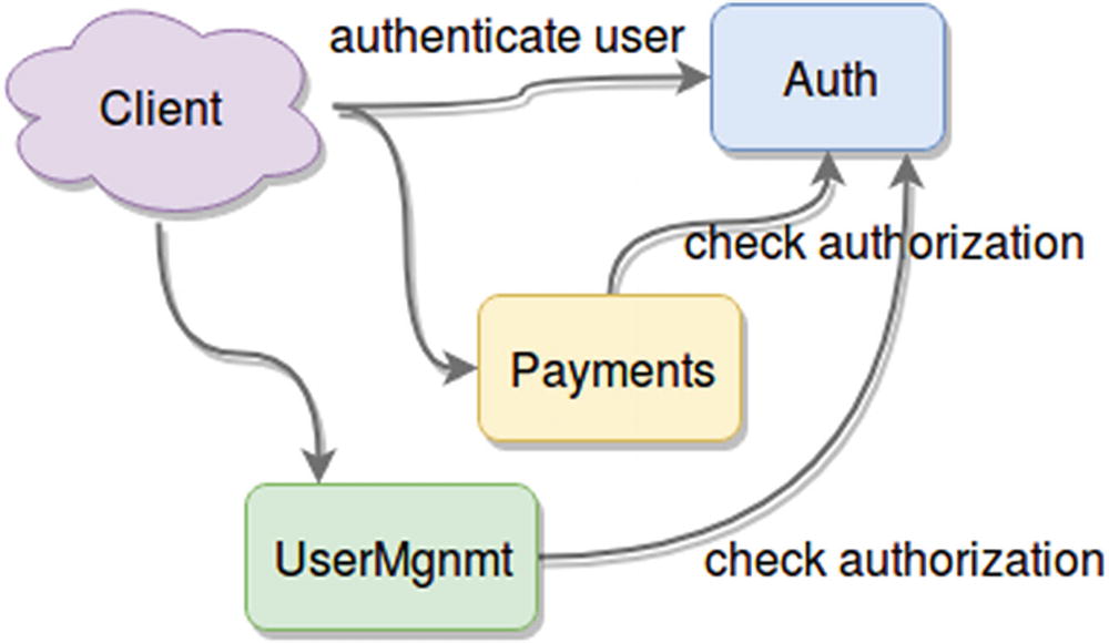
Example of a microservices-based architecture
By splitting your platform into individual services, you gain a new level of control over it that you never had with a monolithic approach. Figure 2-6 shows an example of a fake platform that takes care of payments. It also needs a proper authentication strategy, so it also has a dedicated Auth service. Every user needs to be authenticated against it to start using the platform, and then every request is authorized against the service. Users also have a way to register into the system, which is why there is a UserMgnmt service .
They tend to use your system massively during the weekdays, but never do many payments during that time.
On the weekends, that changes. You only get very specific traffic; not many users log-in, but the ones who do perform around 10.000 payments per second during a short period of two hours.
Gain total control over which component of your application to scale. Based on the known behavior of your customers, you could automate your platform to spawn new instances of the Auth service during the weekdays and the Payment service during the weekends.
Improve the development process, by gaining the opportunity to create groups who can focus on each service, and develop them in parallel without affecting the rest.
Add the ability to switch versions of your components. You could switch your Auth service; as long as you kept the same interface for it, your internal authentication logic could be completely different and no one would notice it.
Gain the ability to reuse components or modules among applications. You could have, for example, different front ends using the same back end, selling customized versions of your application, visually tailored for your customers.
This pattern might sound like the best solution for most problems, but you need to take into account that, as with any other option, you might run into problems because you’re trying to meet your needs with the wrong architecture.
Communication between services needs to be properly planned; otherwise the overall performance of your system might be affected.
Too many microservices might create a chaotic architecture. If that starts to happen, you might want to consider either a different pattern or at least some sort of orchestration service to centralize the data flow.
Deployments of microservice-based architectures can be quite a pain, especially if you’re not properly automating the process. This needs to be a high priority item in your to-do list if you’re planning on going with this approach.
In the end, it’ll be a matter of picking the right tool for the job, as with everything else.
The Broker Pattern
You can think of the broker pattern as a specialization of the microservices architecture. One of the pain points for the latter was that given a high enough number of microservices, you begin to need a form of orchestration; otherwise, your clients start to lose the ability to communicate easily with your platform. You start to burden them with the knowledge of where everything is in your system, and that should not be the case. Ideally, clients should be able to discover your services organically and with minimal previous knowledge.
Here is where the broker pattern comes into play. Its main component is a node called broker, whose purpose is to centralize and redistribute requests among different services.
Another key characteristic of this pattern is that by default it is not the broker that “knows” about its servers; instead, it’s the servers that register with the broker once they come online, and provide all the information it needs to understand the services they provide.
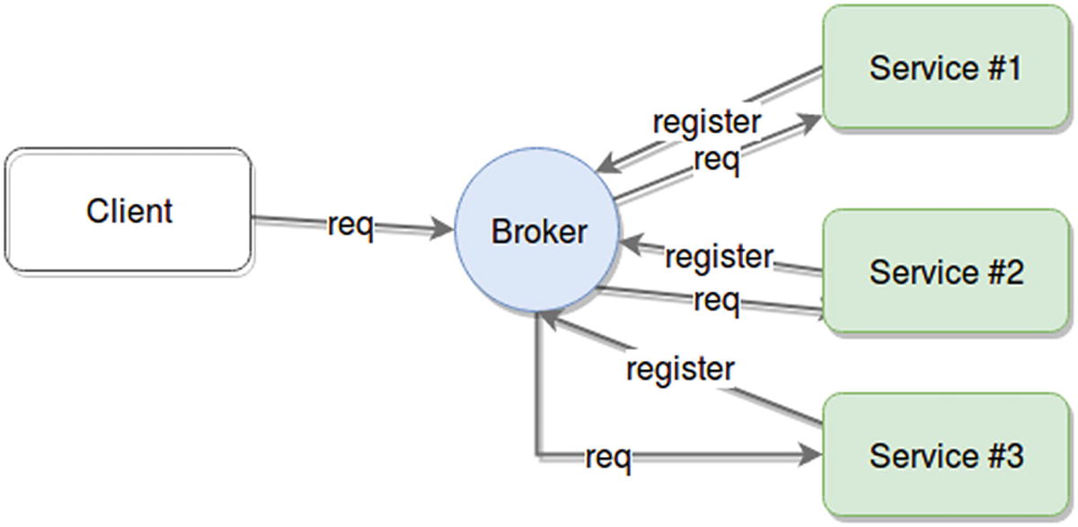
Broker pattern showing communication between client, broker, and servers
The broker becomes the single point of failure. Or put another way, if your broker dies, you lose access to all the services it was providing.
It’s harder to scale your platform unless you also scale up your broker.
It adds an extra layer of indirection between client and services; thus extra latency is added to the request time. This might not be a considerable increase in request time; it all depends on the type of internal logic your code will have.
The logic for picking the right server is complex enough to deserve a whole separate component.
You have multiple providers of the same service, and it’s not relevant who serves each request.
You actually need physical independence between your client and servers.
Lambda Architectures
Lambda architectures are a special pattern designed to provide a high-throughput platform that is able to process very large quantities of data both in real time and in batches.
In a nutshell, processing a lot of data takes time, especially if there are complex calculations. So if your system needs to deal with those amounts of information, what ends-up happening is that either you take those calculations out and do them asynchronously, not caring how long they take (within reason obviously) and allow the users to query those results in real time. This provides a system that is able to properly respond to complex queries by having it all precalculated, but the downside, is that your results show a slightly old version of reality.
Alternatively, you can have a high-performant platform processing real-time data as it is received, and show those results back to the user. Again, that’s great unless you need to do something that also requires the last 5 years’ worth of data. Now your real-time platform is incapable of processing that amount of data properly and you have no way to give your clients the information they need.
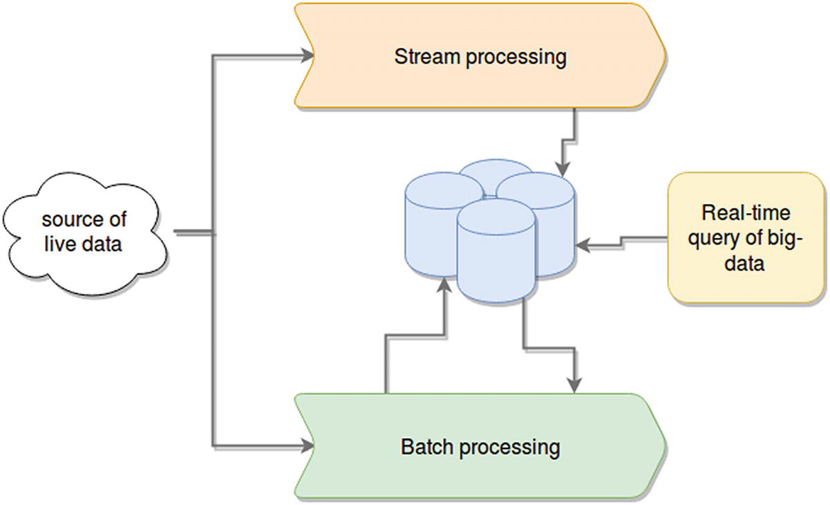
A lambda architecture
- Batch processing
Hadoop is the de facto solution for this scenario. There are multiple ways to work on top of it to process the data, such as simply working using Map/Reduce jobs, Pig,4 or any similar batch-processing framework.
- Real time querying
This component assumes the resulting outputs from either of the previous components still require special capabilities to handle. (That is, the output is still considered big-data, even if you’re just querying it with a simple filter function.) Some good options are Apache Druid7 and Apache Impala.8
A good example of this architecture is the way Twitter handles tweet view counts (and other stats) using a lambda approach. Twitter stores the stream of incoming events into their HDFS, and at the same time they process it using Spark Streaming. The data on the HDFS is later processed and pre-computed using a set of batch-processes which load their output into a real-time database on top of Hadoop.
Yahoo is said to also use this pattern to provide analytics on their advertising data warehouse using Apache Storm and Hadoop for real-time and batch processing of their data, while serving the end-clients through queries using Apache Druid.
With that being said, this is a solution that fits very few and specific scenarios and it’s also a solution that has a very high maintenance cost associated with it since you basically are maintaining two parallel architectures at once, which in turn need to keep a centralized repository of data in a synchronized matter.
Summary
With this chapter’s abbreviated view of so many different architectural patterns I hope you’ve been able to see that there are many ways to solve the same problem. And ideally, you’re also starting to see how some of the scaling problems mentioned in Chapter 1 can be solved using some of the patterns described here.
The next chapter will cover different ways to scale your platform, such as growing horizontally versus vertically, using load balancers, and more.